
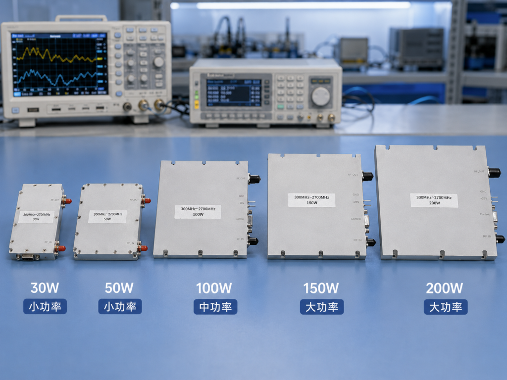
A 300-2700 MHz SDR RF power amplifier is attractive when a lab or OEM team wants one amplifier family to support multi-band transmit experiments, broadband validation, and changing waveform plans. The local CorelixRF specification files include CRF-DS-PA300M2700M variants at 30 W, 50 W, 100 W, 150 W, and 200 W, plus a 200 W test-report folder. That tells buyers there are multiple power levels to review, but it does not replace a current datasheet check for gain, connectors, control, and thermal details.
The keyword looks simple, but the engineering question is rarely simple. SDR sources can generate many waveforms, bandwidths, and duty cycles. The amplifier must be evaluated around the signal it will actually see, not just the frequency range printed in the title.
Start With the SDR Output and Waveform
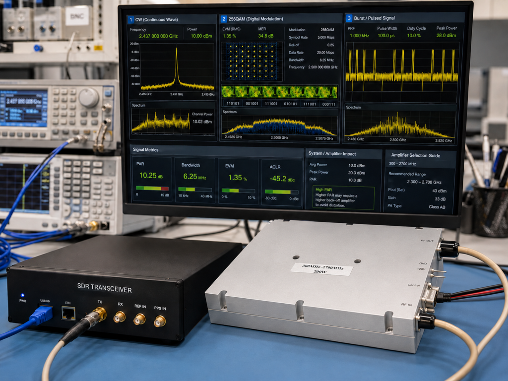
SDR-driven systems often fail at the requirement stage because the source level and waveform behavior are not defined. Before choosing a 300-2700 MHz broadband RF amplifier, document the SDR output power, modulation, peak-to-average ratio, occupied bandwidth, duty cycle, and any expected gain control behavior.
A continuous-wave bench check may not represent the final operating waveform. If the amplifier will handle digitally modulated signals, swept signals, or burst operation, CorelixRF needs that context to recommend a suitable power class and operating margin. A conservative RFQ should also state whether linearity, spectral regrowth, or adjacent-channel behavior is a selection driver.
Why the 300-2700 MHz Window Is Useful
The 300-2700 MHz span can support many sub-6 GHz development tasks, including portions of UHF, L-band, S-band, and lower cellular or telemetry-related test work. For procurement teams, the value is not just broad coverage. It is the possibility of reducing bench complexity when a project must move between frequencies during development.
For engineering teams, the tradeoff is that broadband coverage requires attention to gain variation, input drive limits, thermal behavior, and filtering. A broad amplifier may reduce hardware swaps, but the test plan still needs band-by-band verification. Internal CorelixRF resources on RF signal transmission and RF testing and validation are useful when the amplifier is part of a larger chain rather than a standalone purchase.
Compare Power Classes by Delivered Power
The local files show several CRF-DS-PA300M2700M power classes. A 30 W or 50 W unit can be appropriate for conducted testing, small fixtures, or lower-power transmit validation. A 100 W, 150 W, or 200 W class may be considered when cable loss, distribution hardware, antennas, or higher test levels require more output margin.
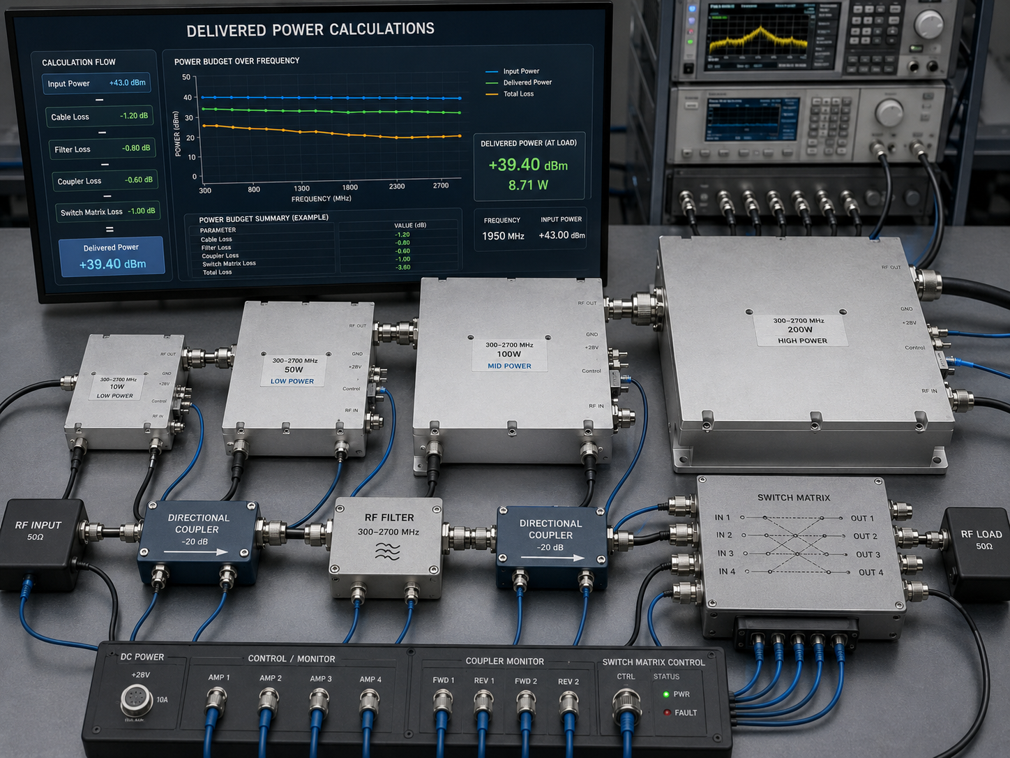
Do not choose the power class only from a target watt number. Calculate the power required at the load or antenna input, then subtract losses and add margin. If a directional coupler, filter bank, switch matrix, or long coax run sits between the amplifier and the device under test, include that loss in the RFQ.
Interface Planning for Multi-Band Benches
A multi-band SDR bench often grows over time. Today it may be a single SDR, amplifier, and load. Later it may include filters, combiners, attenuators, couplers, monitoring receivers, software control, and safety interlocks. That is why connector type, control interface, mechanical format, and cooling should be decided early.
For a standard purchase, review whether the closest standard RF power amplifier platform fits the rack, power supply, airflow, and control environment. For an OEM unit, define the preferred interface and any constraints before asking for a quote. Early clarity reduces back-and-forth and helps CorelixRF identify whether a modified standard design is enough.
Thermal and Protection Questions
A broadband SDR amplifier may be used in ways that are less predictable than a fixed-frequency transmitter. The test team should state the longest expected transmit duration, ambient temperature, airflow restriction, and mismatch scenario. If the load can be disconnected or if antennas may be swapped during development, protection behavior becomes important.
Ask how the amplifier indicates fault states and what monitoring is available. A procurement specification should not assume a protection function unless it is confirmed in the current datasheet or proposal. The safer wording is to request review of mismatch protection, over-temperature handling, and remote status needs for the planned operating profile.
Practical Selection Workflow
- Define the exact operating bands inside 300-2700 MHz.
- Document the SDR output level and waveform characteristics.
- Calculate delivered power after cables, filters, switches, and fixtures.
- Choose a preliminary power class from the local 30 W to 200 W file set.
- Confirm connectors, control, cooling, supply, and mechanical limits.
- Ask CorelixRF to review whether a standard or custom path is best.
This approach keeps the article aligned with real CorelixRF product data while avoiding unsupported claims. It also gives purchasing teams a repeatable way to prepare an RFQ that engineering can defend.
FAQ
What CorelixRF 300-2700 MHz power classes are visible locally?
The local specification filenames include 30 W, 50 W, 100 W, 150 W, and 200 W CRF-DS-PA300M2700M variants. Current datasheets should be checked before final ordering.
Why is SDR waveform detail important?
Different waveforms can change average power, peak power, thermal load, and linearity expectations. CorelixRF needs the waveform context to recommend the right amplifier path.
Can one 300-2700 MHz amplifier replace several narrowband amplifiers?
Sometimes it can simplify a bench, but band-by-band verification is still needed for gain, delivered power, filtering, and system behavior.
What should a buyer ask CorelixRF to review?
Ask for review of operating bands, output power at the load, drive level, waveform, duty cycle, connectors, cooling, protection needs, and documentation requirements.