
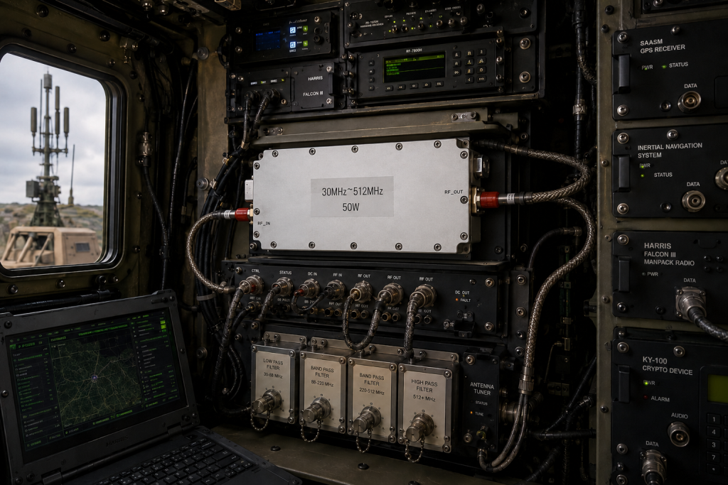
A 30-512 MHz VHF/UHF RF power amplifier is usually selected when a project needs one amplifier path to cover legacy VHF channels, UHF communications, SDR transmit chains, and wideband test signals. The local CorelixRF specification library includes CRF-DS-PA30M512M power classes from 30 W through 200 W, which makes the band useful for teams comparing compact lab use, higher-power validation, and OEM integration requirements.
This article is written for engineers and technical buyers who already know the target frequency span but still need a clean RFQ framework. It avoids assuming a certification, stock condition, or application-specific performance that is not present in the datasheet name. Instead, it focuses on the parameters CorelixRF can review from a real requirement: frequency, output power, drive level, interface, cooling, protection, mechanical format, and test data expectations.
Why 30-512 MHz Is a Practical VHF/UHF Window
The 30-512 MHz range covers a large part of practical VHF and UHF engineering. For many test benches, this window is broad enough to reduce amplifier swaps during waveform development. For OEM systems, it can simplify a transmit chain when a program has multiple operating points, changing channel plans, or SDR-driven waveforms that must be validated across a wide band.
A CorelixRF 30-512 MHz VHF/UHF RF power amplifier should be evaluated as a system component, not only as a wattage number. Engineers should confirm the required output power at the load, the expected modulation or waveform duty cycle, and the margin required after cables, switches, filters, and couplers. If the amplifier feeds a non-ideal antenna, test fixture, or changing load, the RFQ should also describe the expected mismatch environment.
Match Power Class to the Actual Test Job
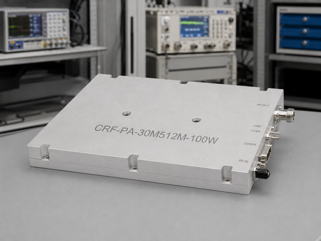
The local datasheet names show 30 W, 50 W, 100 W, 150 W, and 200 W variants for the CRF-DS-PA30M512M family. That range lets buyers avoid two common mistakes: oversizing every bench for worst-case power, or undersizing a platform that must later support longer cables, higher field levels, or additional loss.
For laboratory SDR work, the smaller power classes may be enough when the amplifier is used for controlled conducted testing. For over-the-air validation, radiated immunity support, or integration with lossy distribution hardware, engineers often need more headroom. The useful question is not simply, “How many watts can I buy?” It is, “What delivered power is required at the device, antenna, chamber input, or fixture after all system losses are counted?”
CorelixRF can use that answer to compare a standard RF power amplifier platform with a custom review. Start from the closest standard RF power amplifier platform, then define what must change: connector layout, control interface, enclosure, cooling, or documentation package.
Interface and Control Details to Define Early
A 30-512 MHz amplifier may be installed in a bench rack, vehicle subsystem, enclosure, or OEM payload. The RF interface and control approach should be treated as early design decisions. The RFQ should state preferred RF connectors, nominal input level, supply preference, control requirement, and any interlock or monitoring needs. If the amplifier is part of an automated test system, include expected remote control needs such as enable control, status readback, fault indication, or integration with test software.
The article topic may sound like a product selection issue, but many delays happen because the electrical and mechanical interfaces are unclear. A well-prepared inquiry lets CorelixRF review whether a catalog-like platform is close enough or whether a custom RF amplifier path is more appropriate.
Cooling, Protection, and Duty Cycle Matter
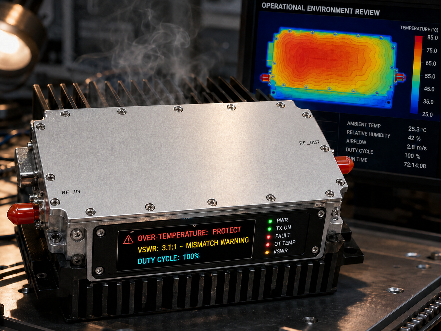
Power amplifiers convert part of the supplied power into RF energy and part into heat. That means cooling should be specified with the same seriousness as output power. A compact amplifier used for short bench bursts may not need the same thermal design as a system running longer dwell times or continuous test sequences.
For VHF/UHF projects, define expected duty cycle, ambient temperature, mounting orientation, airflow limits, and whether the amplifier will sit near other heat-producing equipment. If the load can change or disconnect during operation, ask what protection and monitoring options are available. Good procurement language includes the real operating environment so the selected design is not judged only under ideal lab conditions.
Suggested RFQ Checklist
Use the following points before sending the inquiry:
- Frequency range: 30-512 MHz or any reduced operating window.
- Output power target at the load, not only at the amplifier output.
- Waveform type, duty cycle, peak-to-average behavior, and test duration.
- Input drive level and source type, especially for SDR transmit chains.
- RF connector preference, control interface, supply, and enclosure constraints.
- Cooling environment, airflow limits, and expected ambient temperature.
- Protection needs for mismatch, over-temperature, and operational faults.
- Required test data, drawings, and documentation for internal approval.
A clear checklist helps the supplier respond with a usable recommendation rather than a generic quote. It also gives the buyer a better way to compare power classes across the local CRF-DS-PA30M512M datasheets.
Where This Amplifier Fits in a CorelixRF System Review
The 30-512 MHz band often sits next to other CorelixRF platforms. A test organization may need VHF/UHF coverage in one rack and higher-frequency capability in another. In that case, internal links and documentation matter because the buyer is comparing more than one amplifier family. For broader lab planning, review related CorelixRF pages for RF testing and validation and adjacent amplifier bands before locking the system diagram.
When the requirement is still moving, contact CorelixRF with the operating band, power target, duty cycle, and integration constraints. The engineering review can help determine whether a standard 30-512 MHz unit is close enough or whether a custom enclosure or interface should be quoted.
FAQ
What output power classes are visible in the local 30-512 MHz datasheet filenames?
The local CorelixRF specification library includes CRF-DS-PA30M512M files for 30 W, 50 W, 100 W, 150 W, and 200 W classes. Final selection should be confirmed against the current datasheet and application conditions.
Is a 30-512 MHz amplifier suitable for SDR transmit chains?
It can be a good fit when the SDR output needs external RF power across VHF/UHF channels, but the required drive level, waveform duty cycle, filtering, and delivered power must be reviewed.
Should buyers choose the highest wattage version by default?
No. The right power class depends on system loss, field or load requirement, duty cycle, thermal limits, and margin. Oversizing can increase cost, heat, and integration complexity.
What should be included in a CorelixRF RFQ?
Include frequency range, output power at the load, waveform, duty cycle, input drive, connector/control preferences, cooling environment, protection needs, and documentation requirements.