
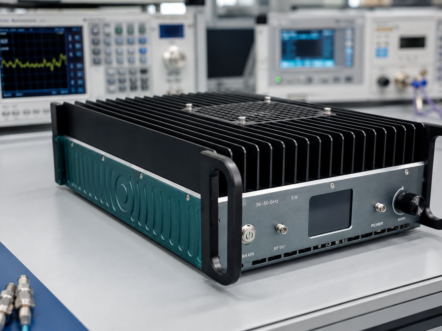
A 36-50 GHz 5W mmWave power amplifier should be evaluated through a bench audit before it is written into a test system bill of materials. The CorelixRF local datasheet identifies CRF-PA-36000M50000M-5W as a GaN solid-state RF power amplifier covering 36 GHz to 50 GHz with 5 W rated output power. It lists 40 dB minimum small-signal gain, +/-8 dB gain flatness, up to 15 dB gain control, 2.4mm-F front-panel input and output, RS485 control, AC 220 V +/-10 percent 50/60 Hz supply, forced-air cooling, 0 to +50 C operation, and a small-unit mechanical format.
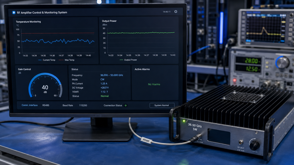
The same source lists real-time temperature monitoring, real-time current monitoring, optional forward/reverse power monitoring, optional input power detection, alarm and fault protection, over-temperature protection, over-drive protection, over-voltage protection, and VSWR protection with alarm functions. It names test and measurement instrumentation, communication systems, RF interference system-level testing, and aerospace control systems as application areas. Those details support long-tail search intent around 36-50 GHz RF amplifier, 5W GaN SSPA, 2.4mm RF amplifier, and small unit microwave amplifier.
Audit Point 1: Name the Measurement Plane
At 36-50 GHz, the measurement plane cannot be vague. The receiving note should say whether output power is measured at the amplifier 2.4mm-F connector, after an adapter, after a cable, or at a device input. This avoids comparing amplifier-level data with delivered-path data. If the amplifier is part of a broader RF front-end platform, the drawing should show every transition that sits between the source and the load.
Audit Point 2: Keep Gain State Visible
The source lists a 15 dB gain control range. That setting should appear beside every frequency point in the test record. A useful bench audit logs source level, gain state, output reading, current, temperature, connector set, and alarm status in one row. Separating gain control from RF data makes later troubleshooting slower and can make two valid measurements look inconsistent.
- Verify 2.4mm-F connector condition and torque practice.
- Set source drive limits before enabling a 40 dB gain stage.
- Record acceptance points across 36 GHz, mid-band, and 50 GHz.
- Keep forced-air inlet and exhaust clearance open.
- Stop after any VSWR, over-drive, over-voltage, or temperature alarm.
Audit Point 3: Decide Optional Monitoring Early
Optional forward/reverse power monitoring and input power detection should be treated as RFQ choices, not late additions. If the bench needs automated logs, ask for the required monitoring package when discussing custom RF systems. If manual acceptance is enough, state that clearly and define which readings the lab will collect itself.
Audit Point 4: Cooling Is Part of the Setup
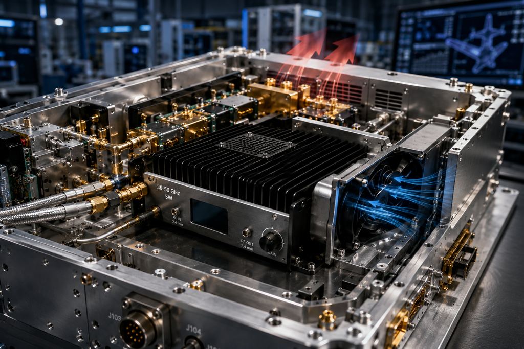
A small-unit forced-air amplifier still needs thermal planning. The audit should record ambient condition, mounting position, airflow clearance, neighboring heat sources, and service access. For repeatable mmWave work, temperature data is not just a safety note; it is part of the evidence that the same test state can be recreated later.
Procurement Closeout
The RFQ should include frequency points, output power target, waveform type, CW or pulse operation, expected duty condition, source level, connector reference plane, gain-control requirement, control interface, cooling environment, and requested test data. The engineering and manufacturing page is a natural next step when buyers need drawing, test, and control-protocol review.
Why This Topic Has Search Value
A search for “36-50 GHz 5W mmWave power amplifier” already contains the band, power class, and amplifier type. The article should therefore answer what happens after the product is shortlisted: how to handle 2.4mm interfaces, where to measure power, how to log gain control, and what documentation belongs in the quote. This is more useful to engineers than a broad explanation of RF amplifier gain.
Bench Audit Record
The audit record should travel with the amplifier during first setup. Include model number, datasheet path, source instrument, maximum source level, cable and adapter list, output reference plane, gain-control setting, frequency points, monitoring fields, alarm response, and cooling condition. It should also separate product facts from project decisions. Frequency range, rated power, gain, control, connectors, monitoring, and protection come from the datasheet. Fixture loss, waveform, delivered power location, and pass/fail criteria come from the project.
That distinction is important for public content and internal purchasing. The datasheet supports a 36-50 GHz 5 W GaN SSPA with 2.4mm-F I/O and forced-air small-unit packaging. It does not prove final system performance after external cables or adapters. When those system-level outcomes matter, the article should guide readers toward RF integration review rather than imply a finished result.
Supplier Review Questions
Before releasing the RFQ, ask several practical questions that connect the datasheet to the bench. Which frequency points will appear in the factory test data? Is gain control tested at one setting or across a range? Which optional monitoring fields are available for this configuration? What mechanical drawing should be used for mounting and airflow planning? Are any project-specific control protocol details needed before purchase? These questions do not add unsupported requirements; they turn the public 36-50 GHz RF amplifier specification into a review-ready request that engineering, purchasing, and the supplier can answer against the same assumptions.
This bench audit now uses the uploaded keyword workbook as a language source, with the terms rf power amplifier, microwave power amplifier, 5w rf amplifier, gan rf amplifier, and high frequency amplifier placed where they match the engineering context. The wording stays focused on bench evidence: connector condition, source control, thermal behavior, and acceptance records for a 36-50 GHz small-unit amplifier.
Bench-Fit Application Scenarios
Use this 36-50 GHz bench audit for the application categories named in the local datasheet: test and measurement instrumentation, communication systems, RF interference system-level testing, and aerospace control systems. In practical terms, the amplifier is a 5W GaN mmWave power stage for controlled lab work where the buyer must define the source, 2.4mm-F RF path, load, cooling condition, and acceptance record before the unit is evaluated.
The real scenario boundary is important. This article can describe a small-unit rf power amplifier being reviewed for instrument benches, communication hardware evaluation, authorized RF interference test setups, or aerospace-control subsystem development. It should not claim field deployment, certification, customer use, inventory, or guaranteed performance in a final system unless those facts are separately documented.
FAQ
What frequency range does CRF-PA-36000M50000M-5W cover?
The local datasheet lists 36 GHz to 50 GHz coverage.
What output power and gain are listed?
The source lists 5 W rated output power and 40 dB minimum small-signal gain.
What RF connectors are listed?
The datasheet lists 2.4mm-F front-panel input and output connectors.
What control and cooling are listed?
The source lists RS485 control and forced-air cooling in a small-unit format.