
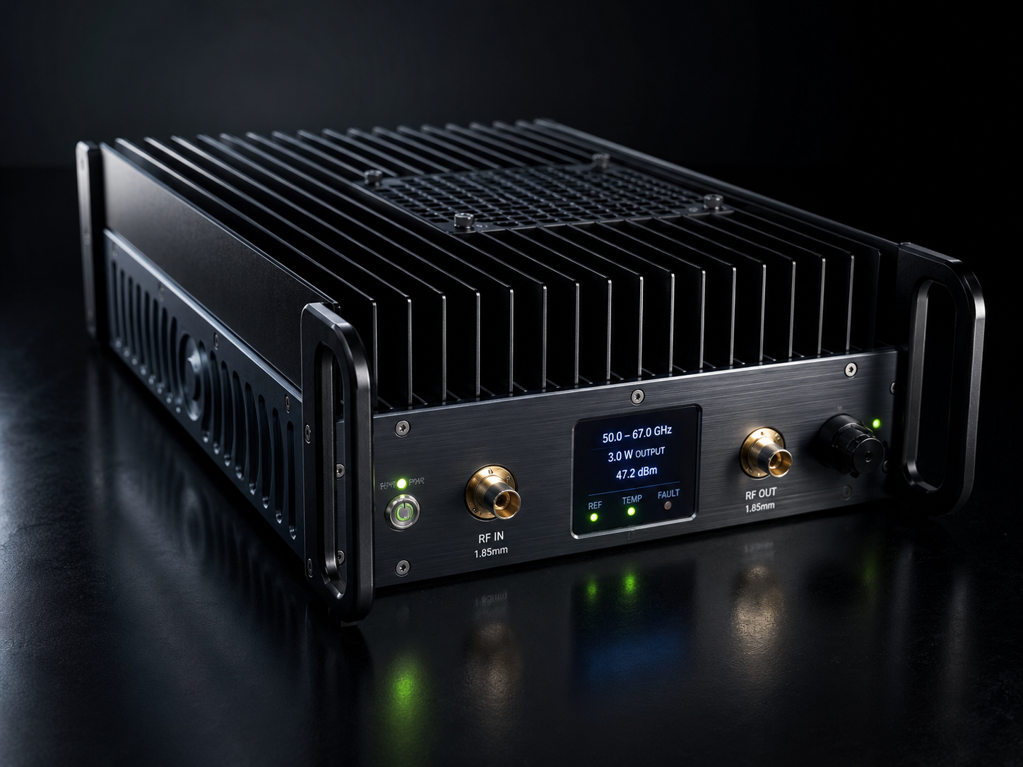
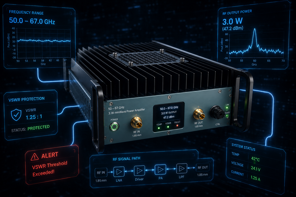
A 50-67 GHz 3W mmWave power amplifier is best specified as part of an integration note, because the useful decision is not only frequency coverage. The CorelixRF local datasheet identifies CRF-PA-50000M67000M-3W as a GaN SSPA covering 50 GHz to 67 GHz with 3 W rated output power. It lists 35 dB minimum small-signal gain, +/-8 dB gain flatness, up to 15 dB gain control, 1.85mm-F front-panel input and output, RS485 and LAN control, AC 220 V +/-10 percent 50/60 Hz supply, forced-air cooling, and small-unit mechanical form factor.
The source also lists 2:1 typical input VSWR, -20 dBc typical harmonics, -60 dBc maximum spurious, real-time temperature monitoring, real-time current monitoring, optional forward/reverse power monitoring, optional input power detection, alarm and fault protection, over-temperature protection, over-drive protection, over-voltage protection, and VSWR protection and alarm functions. It supports searches around 50-67 GHz RF amplifier, 3W GaN SSPA, 1.85mm RF amplifier, and small unit mmWave amplifier.
Integration Note: Frequency Span
The first integration note should split the 50-67 GHz span into working bands. Cable loss, adapter choices, sensor availability, and uncertainty budgets may not be identical across the full range. A buyer can use RF product finder for early comparison, but the RFQ should still list exact operating points and any critical sub-bands.
Integration Note: 1.85mm Interface Discipline
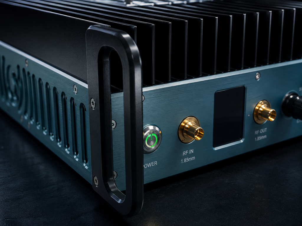
The 1.85mm-F interface is a key part of the requirement. The integration note should specify connector handling, adapter count, torque practice, calibration plane, and replacement rule for worn components. At these frequencies, a connector change is not a minor administrative event. It can change the test state and should trigger a short baseline retest.
- Define the source path and output reference plane.
- State whether acceptance uses fixed gain or several gain settings.
- Log current and temperature with each frequency point.
- Reserve forced-air clearance around the small unit.
- Specify optional input detection or forward/reverse monitoring before quotation.
Integration Note: Control Ownership
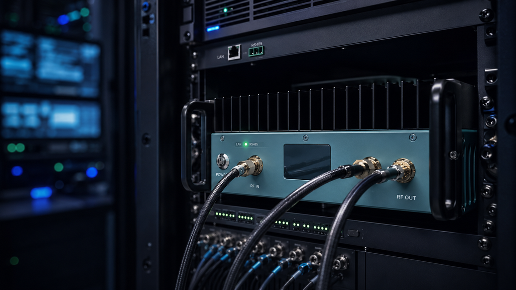
RS485/LAN control should be assigned to a person, script, or host system. The note should state who enables RF, who changes gain, who reads alarms, and how abnormal events are reset. If the amplifier will sit inside a larger automated bench, raise that through RF integration so the control behavior is reviewed with the complete chain.
Integration Note: Public Claim Boundary
The datasheet supports frequency range, rated power, gain, gain flatness, gain control, connectors, control interface, supply, cooling, monitoring, and protection. It does not support statements about inventory, customer deployments, antenna performance, or finished-system compliance. A strong SEO draft should keep this boundary visible because engineers can tell when a page turns a component specification into an unsupported system promise.
What to Put in the RFQ
The RFQ should include operating frequencies, desired output condition, source level, waveform, CW or pulse use, duty cycle if relevant, connector reference plane, gain-control requirement, control protocol, monitoring options, mechanical placement, cooling condition, and documentation request. For nonstandard packaging or monitoring, use custom RF systems rather than forcing the requirement into a standard line item.
Search Intent and Content Angle
The keyword is narrow enough to attract engineers who already know the approximate band. They are likely comparing ultra-wideband coverage with several narrower amplifiers, or they need a 3W stage for fixture, sensor, or system-level work. An integration-note format answers those questions better than a generic product page because it talks about reference planes, connector discipline, control, monitoring, and documentation.
Decision Log for Engineering Review
Create a decision log before the purchase request leaves engineering. List the amplifier model, frequency points, intended source, maximum source setting, adapter set, output plane, gain state, monitoring package, cooling plan, and required supplier evidence. Also write down why a 50-67 GHz amplifier was selected instead of a narrower band. That note helps purchasing compare responses on technical fit rather than only price or lead-time language.
The log can also direct project questions to engineering and manufacturing support when final drawings, test data, or control protocols are needed. This keeps the buying path practical: standard amplifier facts remain visible, while project-specific items move into a technical review instead of becoming assumptions.
When to Escalate from Product Search to Project Review
A 50-67 GHz RF amplifier search can start as a product comparison, but it should become a project review when the amplifier will be installed into a shielded fixture, switched path, automated source rack, or high-frequency measurement station. Escalation is also useful when the buyer needs a special monitoring output, a custom control sequence, or a defined data package for internal signoff. The goal is not to complicate the purchase. It is to keep the RF amplifier, connectors, source, load, software, and documentation aligned before hardware arrives.
For a small-unit amplifier, that alignment should also include placement. Note where the unit sits, how air moves around it, and who owns connector inspection before each high-frequency run and retest.
These integration notes use workbook terms such as rf amplifier, rf signal amplifier, rf microwave amplifier, solid state rf amplifier, and rf amplifier module only where they describe the actual system role. The emphasis remains on integration sequence, RF path definition, control ownership, and the measurement boundary around a 50-67 GHz small-unit platform.
Integration Scenario Map
The local datasheet supports four real application categories for this 50-67 GHz rf amplifier: test and measurement instrumentation, communication systems, RF interference system-level testing, and aerospace control systems. A grounded integration note should therefore describe how the 3W solid state rf amplifier fits into a controlled measurement chain with a source, 1.85mm-F interfaces, load path, cooling, RS485/LAN control, and documented fault response.
For procurement, map the application before asking for a quote: instrumentation bench, communication-system evaluation, authorized RF interference test path, or aerospace-control engineering setup. Each scenario changes what the buyer should request for drawings, test data, control protocol, optional monitoring, and acceptance evidence.
FAQ
What frequency range does CRF-PA-50000M67000M-3W cover?
The local datasheet lists 50 GHz to 67 GHz coverage.
What output power and gain are listed?
The source lists 3 W rated output power and 35 dB minimum small-signal gain.
What RF interface is listed?
The datasheet lists 1.85mm-F front-panel input and output connectors.
What protection functions are listed?
The source lists alarm and fault protection, over-temperature protection, over-drive protection, over-voltage protection, and VSWR protection with alarm functions.