
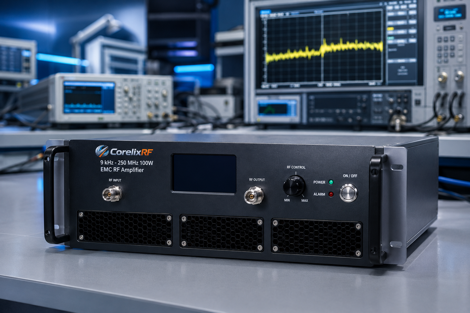
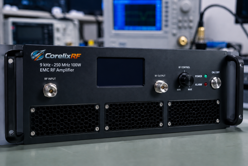
This article is an acceptance test plan for the CorelixRF CRF-PA-9K250M-100W. The local datasheet lists 9 kHz to 250 MHz coverage, 100 W rated CW output power, LDMOS SSPA architecture, 50 dB minimum small-signal gain, N-Female input and output, 19-inch 3U rack-mount mechanical form factor, air cooling, temperature/current diagnostics, alarm protection, and project-ready control interfaces.
Acceptance Purpose
The purpose is to verify that a 9 kHz-250 MHz EMC RF amplifier is ready for the intended lab setup before it becomes part of a larger validation program. The plan does not claim final EMC compliance or field performance. It defines practical checks for frequency coverage, output level, gain behavior, cooling, alarms, and documentation.
Test Equipment
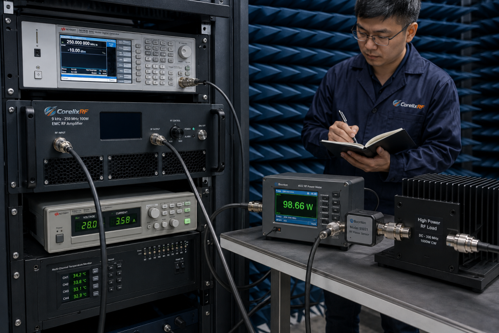
Prepare a signal source, calibrated power measurement path, directional coupler where appropriate, rated load, RF cables, control connection, temperature/current monitoring access, and a test log. The output load and measurement path should be rated for the frequency range and power class. If the setup includes antennas or external fixtures, define the reference plane before testing starts.
Test Sequence
- Inspect the rack, airflow, RF connectors, cables, load, and source settings.
- Confirm that the source drive is low and that the amplifier output is correctly terminated.
- Enable monitoring and record baseline current, temperature, and alarm state.
- Step through representative frequency points across 9 kHz to 250 MHz.
- Increase drive gradually until the planned output level is reached.
- Record output power, source level, temperature, current, gain state, and alarms at each point.
Acceptance Criteria
The acceptance record should show that the amplifier can be operated at the agreed frequency points, with the agreed measurement reference plane, without unexpected alarm behavior under the agreed duty condition. Because the datasheet lists 50 dB minimum gain, the source and attenuation settings must be part of the record. A solid state RF amplifier acceptance test is incomplete if it only records the final output number.
Fault Response
If an alarm appears, remove RF drive, preserve the log, and document frequency, source level, output condition, load condition, temperature, current, and operator action. Do not keep increasing drive after an unexplained alarm. If the test setup needs nonstandard control, packaging, or protection behavior, move the project to a custom RF amplifier review.
Reporting Format
The final report should include the model, serial or project identifier if available, test date, equipment list, calibration reference, frequency points, output readings, drive levels, temperature/current data, alarm status, and any deviations. Link readers to the broader EMC RF amplifier category and CorelixRF Contact CorelixRF page for requirement review.
Data Table Fields
The acceptance table should have columns for frequency, source level, attenuation state, output power, load description, current, temperature, alarm state, and operator notes. Add a separate field for the reference plane. If the amplifier is measured after a coupler or fixture, the report should not imply that the value was measured directly at the amplifier connector.
Search intent for this plan includes EMC RF amplifier acceptance, 9 kHz to 250 MHz RF amplifier, low frequency RF power amplifier, 100W EMC amplifier, and LDMOS SSPA test plan. Engineers using those terms are often preparing a lab procedure, so an acceptance-plan structure is more useful than a general buying guide.
Final Review Before Lab Release
Before the amplifier is released for regular use, confirm that the report identifies test equipment, measurement uncertainty where available, output path rating, source drive limits, airflow status, and alarm response. If the setup will be used by multiple teams, place the operating limits where operators will actually see them. A clean report reduces support questions and helps later teams compare future measurements against the original baseline.
The closeout review should include a clear exception log. If a frequency point was skipped, if a load was substituted, if the rack airflow differed from the final installation, or if an alarm occurred and was resolved, write it down. Acceptance plans are most useful when they preserve these details. They prevent later teams from treating a conditional result as a universal approval.
After closeout, store the report with the RFQ, datasheet reference, and operating notes. This gives purchasing, engineering, and lab users one common source of truth when the amplifier is moved, reused, or quoted again for a related project.
The report should also state who approved release for regular use. That final name or team creates accountability and makes later troubleshooting easier.
If the amplifier will support recurring EMC work, schedule a periodic baseline check. Repeating a small set of accepted frequency points helps detect cable, load, airflow, or operator-procedure changes before they affect a larger test campaign.
FAQ
What is the primary search phrase for this article?
The primary search phrase is 9 kHz-250 MHz EMC RF amplifier.
What output power does the datasheet list?
The local datasheet lists 100 W CW rated output power.
Why is this written as an acceptance plan?
Low-frequency EMC amplifier buyers often need test sequence, reference-plane, cooling, and alarm criteria before the amplifier enters a lab workflow.
Does this article claim compliance certification?
No. It describes acceptance planning only and avoids unconfirmed certification claims.