
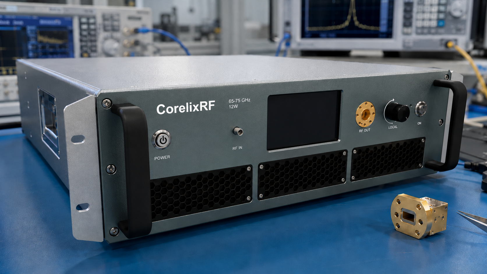
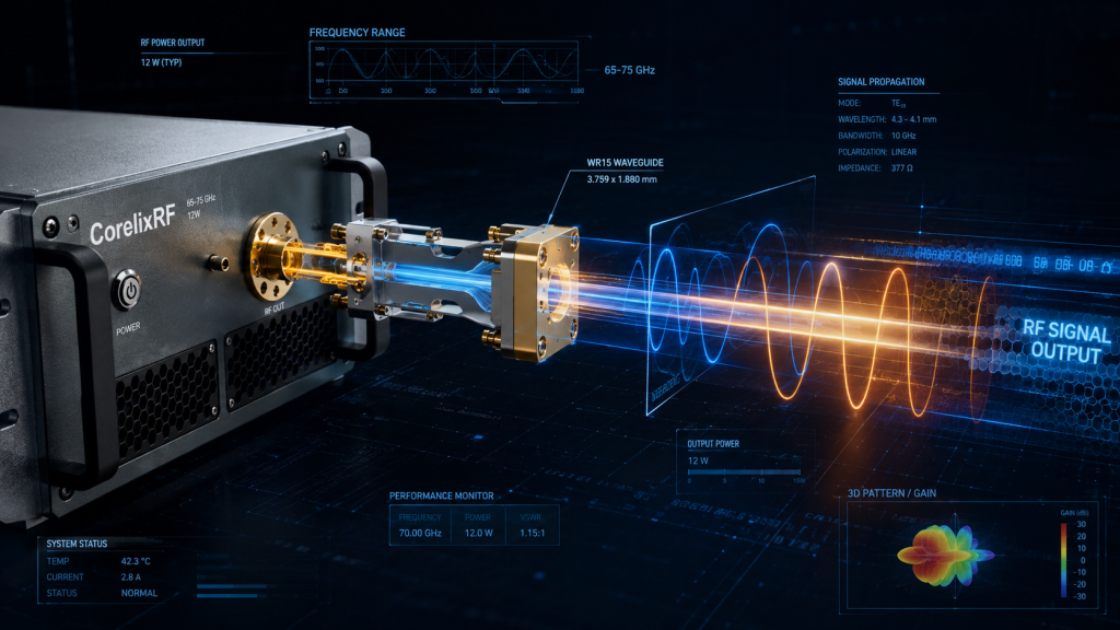
This article is a waveguide checklist for the CorelixRF CRF-PA-65G75G-12W. The local datasheet lists 65 GHz to 75 GHz coverage, 12 W rated CW output power, GaN SSPA architecture, 42 dB minimum small-signal gain, WR15 input and output, gain control up to 15 dB, forced-air 19-inch 3U configuration, temperature/current diagnostics, and alarm protection.
Checklist Use
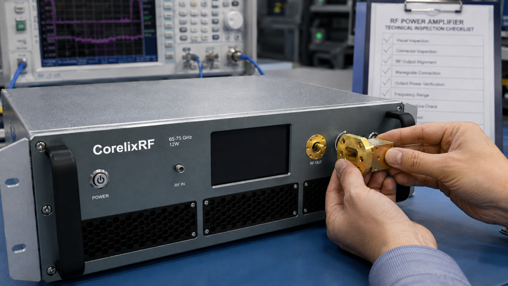
Use this checklist before a mmWave power amplifier is installed, powered, or accepted. At 65-75 GHz, mechanical setup and RF performance are tightly connected. A small waveguide change can affect loss, match, repeatability, and measured output. The article intentionally reads like a checklist rather than a narrative guide.
Pre-Install Checks
- Confirm the amplifier model, frequency range, output power class, and WR15 input/output interfaces.
- Identify every waveguide section, bend, transition, coupler, load, and measurement instrument.
- Verify that the rack has space for the forced-air 3U configuration and that airflow is not blocked.
- Record the approved source, drive limit, gain-control starting point, and output reference plane.
Waveguide Path Checks
- Inspect WR15 flanges before mating.
- Avoid unsupported waveguide weight on the amplifier ports.
- Keep a written list of approved hardware.
- Mark the direction of couplers and the location of any calibration plane.
- Do not substitute adapters after acceptance without recording the change.
Power-On Checks
- Start with the RF source disabled or at a controlled low level.
- Verify the load or measurement path before enabling RF drive.
- Increase drive gradually and log frequency, source level, gain state, output reading, current, temperature, and alarm state.
- If an alarm appears, remove drive first and document the condition before reset.
Acceptance Checks
Acceptance should include representative points across 65-75 GHz, not just one convenient frequency. Record the exact WR15 path used during the test. Include output power, gain behavior, temperature, current, alarm state, and any gain-control setting. This makes future comparison possible when another engineer rebuilds the setup.
Common Setup Errors
The common mistakes are loose mechanical alignment, undocumented adapter changes, blocked airflow, excessive source drive, wrong coupler direction, and treating the WR15 path like a low-frequency cable run. A RF power amplifier at this frequency needs careful mechanical discipline. If the project requires special packaging or interface behavior, request a custom RF amplifier review early.
Related CorelixRF Paths
Readers comparing product families can review CorelixRF CW solid-state RF amplifier options. If the project is closer to immunity or interference validation, the EMC RF amplifier category may be relevant. For project review, use Contact CorelixRF.
Setup Owner Checklist
Assign an owner for waveguide inspection, an owner for the source drive setting, and an owner for the acceptance log. Shared mmWave equipment fails procedurally when everyone assumes someone else checked the output path. The checklist should be signed or otherwise recorded before high-power operation. This does not need to be bureaucratic; it needs to prevent undocumented setup changes.
Long-tail search intent for this article includes 65-75 GHz mmWave power amplifier, WR15 amplifier checklist, V-band power amplifier setup, and mmWave amplifier waveguide integration. The checklist format is deliberate because those readers are often preparing a physical setup, not reading a general product overview. Short, inspectable steps reduce risk better than a continuous essay.
Handoff Notes
At handoff, give the next user the accepted waveguide path, approved source limits, measured baseline points, alarm response, and any restrictions on adapter changes. If the amplifier moves racks, if a different load is used, or if the source is changed, the handoff note should require a new low-power baseline. That protects both the amplifier and the validity of future measurements.
The WR15 handoff should also identify storage and handling practice. Keep protective covers available, separate approved waveguide hardware from unknown adapters, and mark any part that has been dropped, over-tightened, or otherwise suspect. Mechanical condition is part of RF condition at these frequencies. If the checklist is used in a shared lab, place it near the equipment rather than burying it in a purchasing folder.
For acceptance review, do not reduce the result to a single output number. The useful record connects output power to frequency point, waveguide path, source level, gain setting, temperature, current, and alarm status. That makes the checklist valuable for future troubleshooting and for conversations with CorelixRF if a project-specific configuration is needed.
If the checklist is used for quotation, attach photos or drawings only in the internal RFQ package if allowed by company policy. The public article should remain text-based and limited to general setup guidance.
Also note the storage location for approved waveguide parts and covers. A checklist is easier to follow when the correct hardware is physically near the amplifier and clearly separated from unverified lab adapters.
FAQ
What is the primary search phrase for this article?
The primary search phrase is 65-75 GHz mmWave power amplifier.
What waveguide interface is listed?
The local datasheet lists WR15 input and output.
Why is the article checklist-style?
Waveguide integration is procedural, so a checklist better matches the way engineers inspect mmWave setups.
Is visual media required?
No. The article is text-only and should not include visual media.