
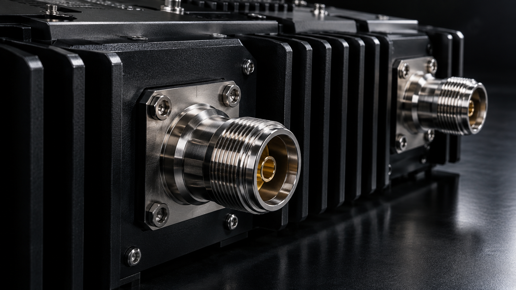
Choose a broadband RF power amplifier for SDR or EMC testing by defining the signal, required power at the measurement plane and evidence needed across the operating band. For SDR, identify the waveform and signal-quality limits. For EMC, identify the test method, calibrated signal path and field or power requirement. A shared frequency range does not make those acceptance tasks interchangeable.
Start with the exact frequency range, output definition, input drive, gain, connectors, cooling, control and load conditions. Use those requirements to compare configurations, then request evidence for the shortlisted build.
Broadband RF Amplifier Selection Map
Use the table below as a selection map, not as a replacement for model-level datasheets.
| Requirement question | What to check | Why it matters |
|---|---|---|
| Frequency span | Minimum and maximum operating frequency | A 2-8 GHz amplifier and a 2-18 GHz amplifier solve different system problems. |
| Output power | Rated power across the required band | A single headline wattage does not prove full-band usable power. |
| Gain and flatness | Small-signal gain, gain control, flatness tolerance | These values drive source level, calibration, and margin. |
| Signal type | CW, pulsed, modulated, SDR, OFDM, sweep | Waveform conditions affect heat, compression, and acceptance data. |
| Interface | RF connectors, control, monitoring, supply | A correct RF amp still fails if it cannot integrate mechanically or electrically. |
| Cooling | Air, conduction, external heat sink, liquid cooling | Broadband and high power amplifier projects often fail at the thermal boundary. |
| Evidence | Curves, test data, drawings, protection notes | Procurement approval depends on verifiable records, not only category claims. |
Common Broadband and Wideband Families
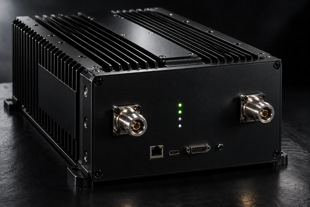
The existing platform examples span 300–1200 MHz, 300–2700 MHz, 2–6 GHz, 2–8 GHz, 2–18 GHz, 6–18 GHz and 18–40 GHz. These are separate coverage examples, not a single amplifier or a guarantee of every power level and interface in every band. Check the exact model datasheet before shortlisting.
First decide whether one broadband path or several band-specific paths suit the system. The broadband-versus-narrowband architecture comparison addresses switching, calibration and system tradeoffs. Once that architecture is chosen, use the SDR and EMC requirements below to assess the amplifier configuration.
How to Compare Full-Band Performance
Broadband does not mean flat, identical performance at every frequency. Buyers should request output power across the band, gain curve, gain flatness, harmonics, spurious results, and input drive limits. If the project needs a high power RF amplifier, ask whether rated power is available at the amplifier output connector or after system losses. If the application needs a linear RF amplifier response for modulated signals, define the signal and acceptance metric early.
The key question is where the power is needed. A lab may care about the amplifier output connector. A chamber system may care about the antenna input. A waveguide setup may care about the flange reference plane. An SDR amplifier chain may care about gain budget, compression margin, and unwanted emissions. The RFQ should define the reference plane before comparing models.
Application Paths for Broadband RF Power Amplifiers
For an SDR chain, specify occupied signal bandwidth as well as the full tuning range. Record modulation, crest factor or peak-to-average behavior, source level, filters and downstream load. Operating-frequency coverage alone does not establish distortion performance for that waveform.
SDR: Connect Each Signal Requirement to Evidence
| Requirement | Why it changes the decision | Evidence to request |
|---|---|---|
| Operating range and signal bandwidth | The tuning span and the bandwidth occupied at one time answer different questions. | A frequency plan and measurements using the required waveform and bandwidth. |
| Average output, peaks and signal quality | A rated or saturated power value does not establish acceptable modulation quality. | EVM or the applicable distortion result versus measured output, with waveform and measurement conditions. |
| Source level and RF path | Gain, path loss and source startup behavior affect the amplifier input. | Input limits, measured path loss and an agreed drive plan. |
| Run duration and thermal conditions | A brief measurement may not represent a sustained run. | Test duration, cooling configuration, temperature record and output stability. |
| Gain and control state | Repeatable measurements need a known commanded and returned state. | Configuration-specific command definitions and a run log. |
Use the EVM-versus-output-power guide to define a modulation-quality operating window. Request results for the actual signal rather than treating a CW wattage as an EVM guarantee. Keysight’s EVM-versus-power measurement description illustrates why waveform conditions and measured PA output belong together.
For EMC and immunity-related setups, the buyer should define sweep range, dwell time, antenna factor, chamber loss, coupler location, and power target. A broadband RF power amplifier may be part of the chain, but the final field strength depends on more than amplifier wattage.
EMC: Define the Complete Test Chain
| Requirement | Why it changes the decision | Evidence to request |
|---|---|---|
| Test method, sweep and modulation | The required operation is defined by the selected test procedure. | An agreed frequency range, modulation, dwell and acceptance method. |
| RF power and field target | Amplifier output alone does not establish the field at the test location. | System calibration and the relevant antenna, cable, coupler and chamber conditions. |
| Power across the band | One favorable frequency cannot establish the complete sweep capability. | Frequency-dependent output under the specified drive and operating conditions. |
| Load and reflected-power response | A protection event can interrupt the required test level. | Permitted load conditions, available monitoring, response and reset requirements. |
| Thermal run and logged state | The system must sustain the specified sequence and identify interrupted runs. | Temperature and operating-state records for a representative sequence. |
Rohde & Schwarz’s introduction to EMC amplifiers places amplifier selection within radiated-immunity testing. A model datasheet is only one input; it is not a system-level compliance result.
For communications and RF system integration, the request should include signal type, operating band, thermal condition, control needs, and monitoring requirements. A radio frequency amplifier used in a production rack may need different documentation than the same amplifier used in a bench experiment.
Evidence to Request Before Purchase
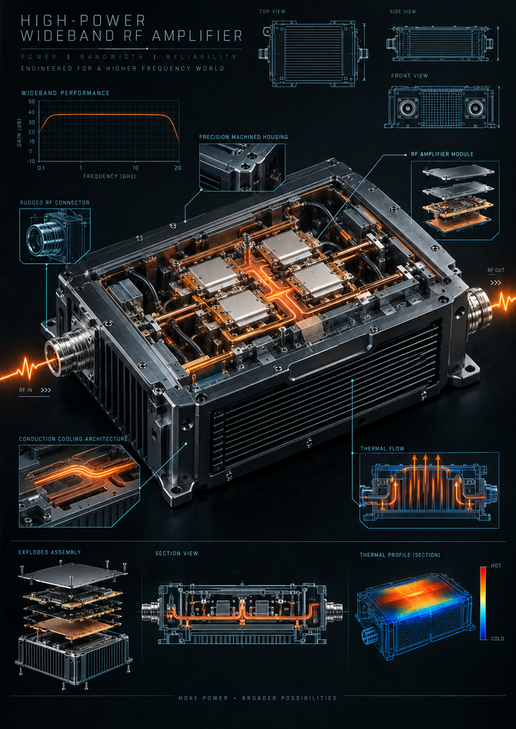
A strong broadband amplifier quote should include model datasheet, mechanical drawing, RF connector definition, power supply requirement, cooling method, control interface, monitoring options, and test data across the required band. For higher-power platforms, also request thermal conditions, protection logic, reflected-power handling, and reset behavior.
When Is the Requirement Ready for Engineering Review?
Move to engineering review when the buyer can state the band, output power, waveform, duty cycle, input drive, connector plan, cooling method, and installation limits. Move earlier if the project has unusual constraints, such as a fixed rack envelope, liquid cooling requirement, special control protocol, high reflected-power risk, or a need for project-specific test records.
Where a standard platform does not match the required interface, cooling or control behavior, identify the specific gap for engineering review. Request a written feasibility and evidence plan before treating a modified or custom configuration as available.
FAQ
What is a broadband RF power amplifier?
A broadband RF power amplifier operates across a wide frequency range and is used when a system needs RF power over multiple bands, swept conditions, or wideband signal plans.
What is the difference between broadband and wideband RF amplifier wording?
Both terms are used by buyers. Broadband usually describes broad operating coverage, while wideband often emphasizes wide frequency span or signal bandwidth. The project requirement should define the exact range.
Does broad frequency coverage guarantee wideband modulation quality?
No. Define the occupied bandwidth, waveform, output level and acceptable distortion, then request measurements under those conditions. Frequency coverage and modulation quality are separate requirements.
Can one broadband RF amplifier replace several narrowband amplifiers?
Sometimes, but the decision also depends on switching, calibration, full-band output, linearity and system cost. Complete the architecture comparison before assessing the SDR or EMC acceptance requirements in this article.
What should I prepare before requesting a quote?
Prepare frequency range, output power, waveform, duty cycle, input drive, connectors, cooling, control interface, monitoring needs, reference plane, and required test evidence.