
A broadband vs narrowband solid state power amplifier decision can look simple until your rack design includes switches, filters, and calibration paths. One broadband unit and several narrowband units may have different support needs. A low amplifier price can hide substantial integration work.
Compare complete configurations against the same frequency plan, usable output, signal quality, and switching limits. Start with your required operating points, then check which arrangement meets them with acceptable integration work. A bandwidth label alone cannot establish efficiency, delivered power, or total cost.
Throughout this article, any CorelixRF technical-documentation support, application review, customization path, or test-data recommendation is subject to project review, the supplied product configuration, and the project’s requirements.
What bandwidth does your system actually require?
Your requirement must distinguish carrier-frequency coverage from the bandwidth occupied by each signal. A PA that operates across several carrier bands does not automatically preserve every wideband waveform at the requested power.
Separate RF coverage from modulation bandwidth
Describe the signal presented to the amplifier, including whether frequencies occur sequentially or simultaneously. That distinction affects the candidate architecture before any comparison of enclosure size or price.
- List every required carrier range and any gaps between ranges.
- Record occupied signal bandwidth and the applicable quality criterion.
- Identify simultaneous carriers, swept signals, and fixed-frequency operation.
Define continuous coverage and discrete operating bands
The gaps matter as much as the endpoints. A continuous sweep cannot tolerate an uncovered interval merely because both endpoint frequencies appear on a datasheet; a fixed-band application may accept those gaps. Use the standard model selection to identify candidates, then request evidence against your actual plan.
| Frequency need | Requirement to record | Evidence to request |
|---|---|---|
| Continuous sweep | Uninterrupted operating interval | Full-band characterization |
| Discrete bands | Each range and permitted gaps | Results for every required band |
| Wideband signal | Occupied bandwidth and waveform | Quality at operating power |
Separate these requirements before comparing quotations. Key Takeaway: A clear frequency plan prevents carrier coverage from being mistaken for signal bandwidth.
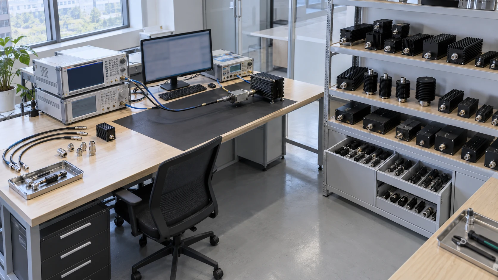
When should multiple narrowband units be compared?
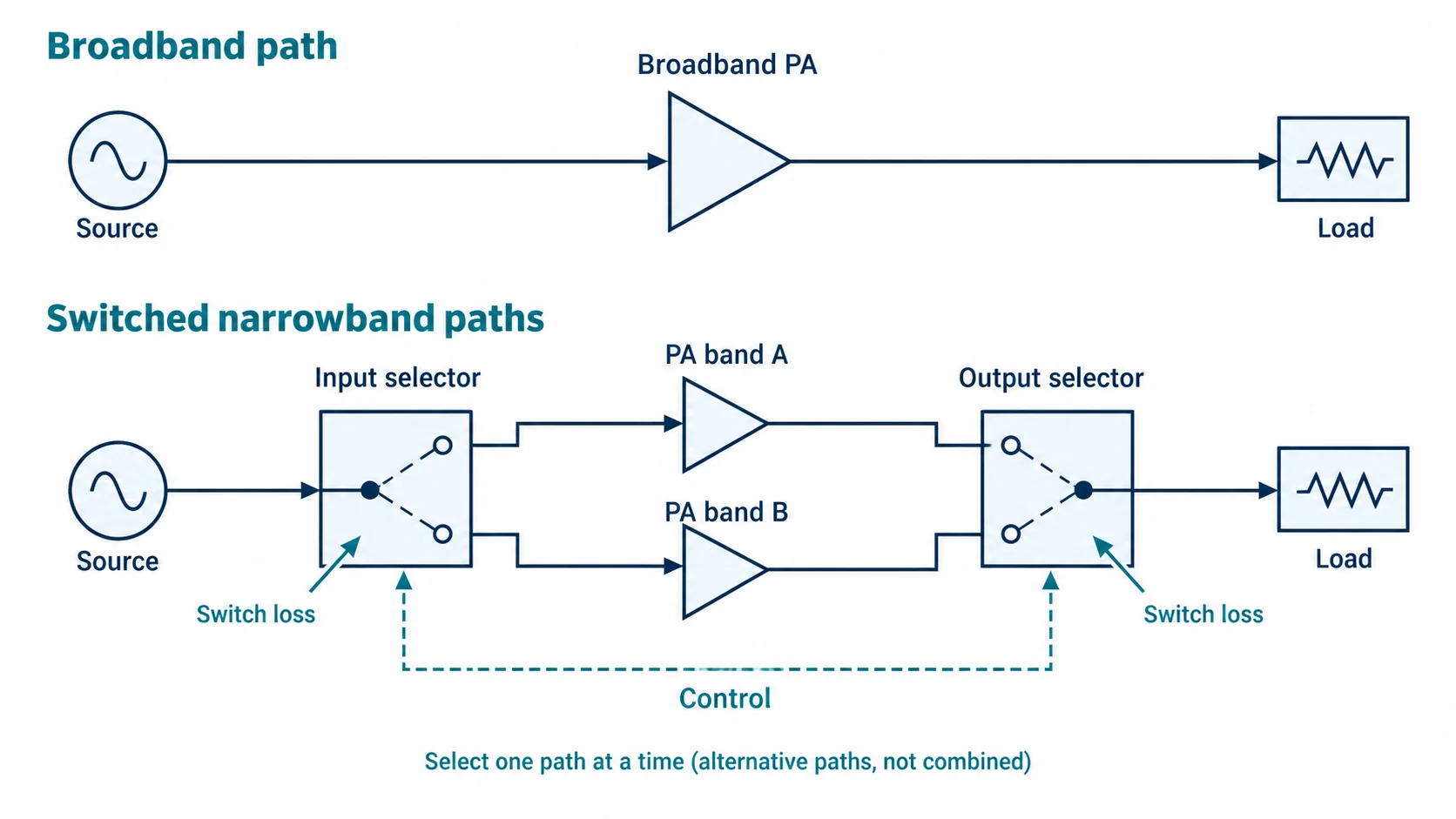
Multiple narrowband amplifiers are worth comparing when the required bands can operate through separate, selectable paths. Include their switching and control hardware within the same boundary used for the broadband candidate.
Build an equivalent multi-band configuration
A bank of PAs needs a defined method for selecting the intended path and isolating inactive equipment.
- Include input and output selectors, where required.
- Specify safe drive inhibition during path changes.
- Record the frequency and power limits of every added component.
Account for operational constraints
Count the path changes before counting the boxes. Switching may introduce settling, control verification, and separate calibration records. Review narrowband amplifier candidates as parts of that configuration, including what happens after a failed or incomplete selection.
| Configuration item | Broadband candidate | Multiple-PA candidate |
|---|---|---|
| RF routing | Verify any internal switching | Define external path selection |
| Controls | Establish mode and fault handling | Coordinate selectors and PA enable |
| Calibration | Record each operating configuration | Record every selected path |
A complete configuration makes the comparison reproducible. Key Takeaway: Selectable narrowband paths need a routing and control specification alongside the amplifiers.
What filtering and load conditions affect the system?
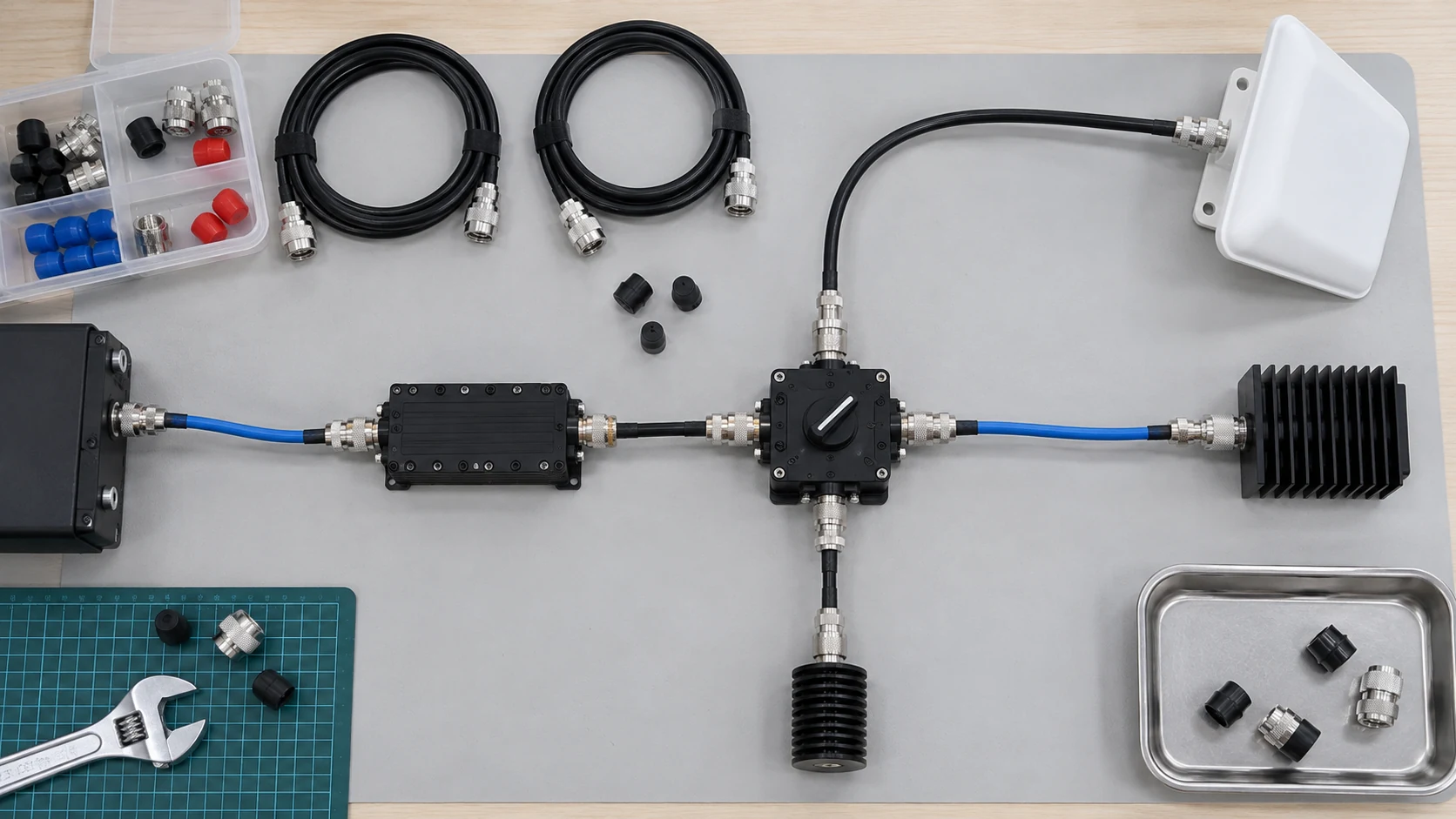
Filters, switches, cables, antennas, and loads can restrict the useful frequency range even when the amplifier covers it. The system boundary must also include the load conditions under which the requested output remains available.
Review output filtering and path compatibility
Trace the path from the PA connector to the intended load. Check component specifications against frequency, waveform, power, and temperature rather than assuming a physically compatible connector proves RF compatibility.
- Confirm filter passbands and rejection requirements.
- Include frequency-dependent cable and switch losses.
- Check antenna or load coverage and applicable power ratings.
Specify mismatch and protection expectations
A covered frequency is not yet a qualified path. Obtain the allowed mismatch conditions and the resulting output, fault response, and recovery behavior for each band. The amplifier-and-antenna integration information provides a starting point for identifying the interfaces that need review.
| Path element | Possible limitation | Verification |
|---|---|---|
| Filter or switch | Loss, band coverage, power handling | Data for the installed configuration |
| Cable assembly | Loss and connector suitability | Measured path-loss record |
| Antenna or load | Mismatch and operating range | Load data and protection agreement |
Check the complete path at its limiting conditions. Key Takeaway: A bandwidth upgrade requires compatible downstream hardware, not just a wider-range PA.
How consistent is usable output across the band?
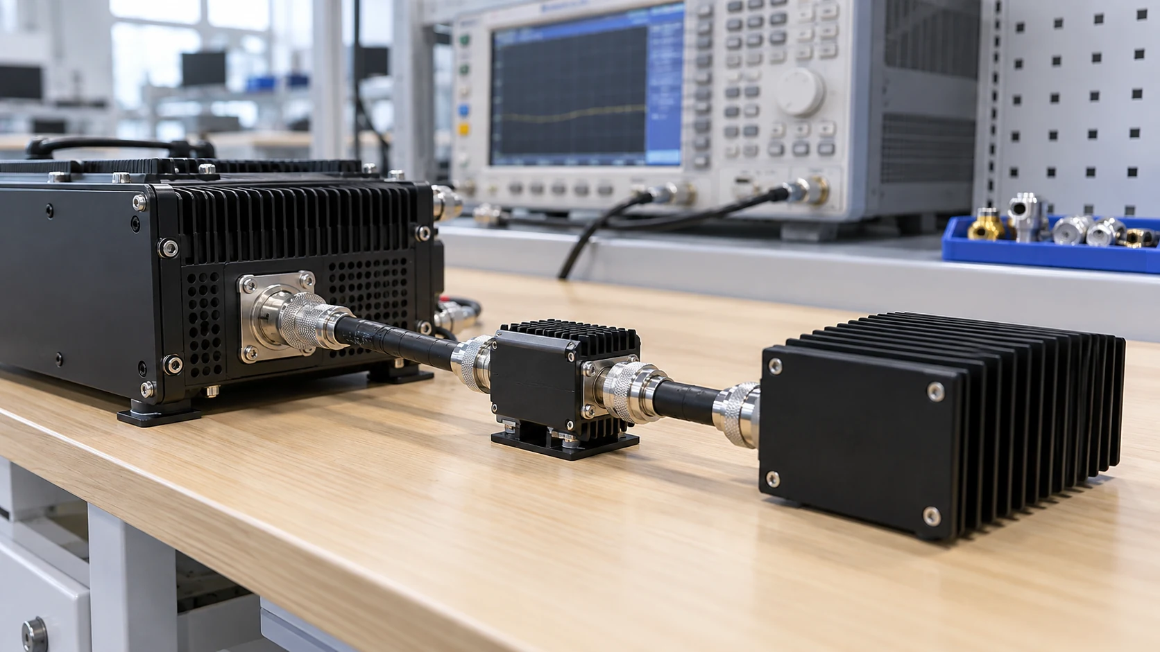
Usable output must meet the required signal quality at every necessary frequency, including band edges. A peak value at the center of a range cannot establish performance elsewhere.
Check band edges and local performance limits
Request frequency-resolved results at the specified operating conditions. Where output varies, determine whether the lowest qualified result still meets the load requirement after path loss.
- Include both band edges and other required test points.
- Separate typical curves from guaranteed limits.
- Record temperature, duty cycle, load, and supply conditions.
Define power limits with the required signal quality
The usable limit comes from the application. Saturated power, a compression-point rating, and power meeting a modulation-quality limit describe different conditions. Keep the output-power candidate list tied to a common acceptance definition before ranking models.
| Candidate result | Missing context to resolve | Buyer action |
|---|---|---|
| Center-frequency maximum | Performance at other frequencies | Request a frequency matrix |
| Saturated output | Quality at normal operation | Specify the intended waveform |
| Guaranteed minimum | Applicable test conditions | Match them to the system |
Compare the same output definition across the full requirement. Key Takeaway: Preserve the weakest required operating point in the selection table.
How should gain flatness and signal fidelity be compared?
Compare only the response metrics that affect your waveform, using consistent signal and measurement conditions. Gain variation across carrier frequencies and distortion within an occupied signal bandwidth answer different engineering questions.
Identify application-relevant response metrics
A level-controlled sweep may accommodate gain variation through calibration, provided drive and output limits allow it. A wideband waveform may also require phase or group-delay assessment within its occupied bandwidth.
- Identify allowable amplitude variation and available level correction.
- Add phase or delay limits when the waveform requires them.
- Define the distortion measurement and its operating power.
Agree test signals and measurement conditions
Use the signal that must survive the amplifier. Compare the same occupied bandwidth, carrier arrangement, output level, and measurement reference plane. Keep any equalization or predistortion enabled during testing explicitly within the supplied system scope.
| Metric | Question it answers | Condition to keep fixed |
|---|---|---|
| Gain response | How does amplification vary? | Frequency range and power level |
| Phase or group delay | Is waveform timing affected? | Occupied bandwidth and reference plane |
| Distortion metric | Does the output meet quality needs? | Waveform and correction settings |
Do not make an irrelevant metric a mandatory purchase constraint. Key Takeaway: Let waveform requirements determine the response measurements in the acceptance plan.
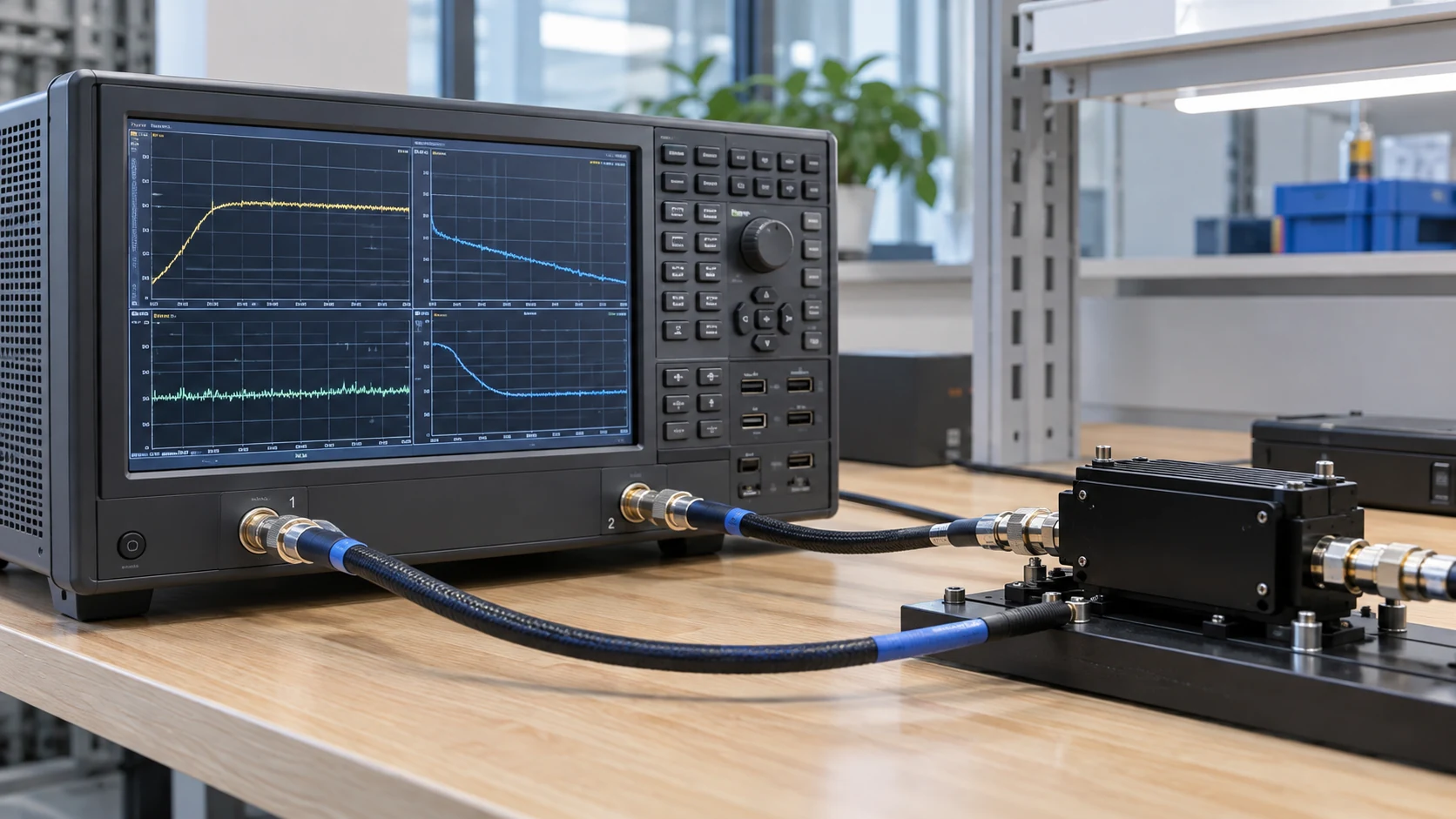
How does efficiency vary across operating conditions?
Efficiency must be compared at the actual frequencies and output levels using the same definition and system boundary. Neither broadband nor narrowband operation establishes a universal efficiency advantage.
Compare frequency and output operating points
Ask for RF output and electrical-input measurements at normal operation, including any required back-off. Distinguish an amplifier-stage DC measurement from wall input that includes conversion losses, fans, and controls.
- Identify the efficiency definition and measured input boundary.
- Record waveform, output level, frequency, and temperature.
- Include standby and low-output states when they matter operationally.
Translate measured input into thermal requirements
Follow the heat to the installation boundary. An enclosure-level assessment must account for energy entering and leaving that enclosure; do not assign all external cooling-system consumption to heat generated inside the PA. Review the rack cooling requirements alongside candidate-specific thermal data.
| Measurement | Boundary to state | Integration use |
|---|---|---|
| PA DC input | Included amplifier electronics | Stage-level comparison |
| Equipment wall input | Included supplies and auxiliaries | Electrical-service planning |
| Thermal requirement | Enclosure and cooling interface | Installed cooling assessment |
Request data for the operating schedule you intend to use. Key Takeaway: Compare energy and cooling demands at normal working points, not from bandwidth labels.
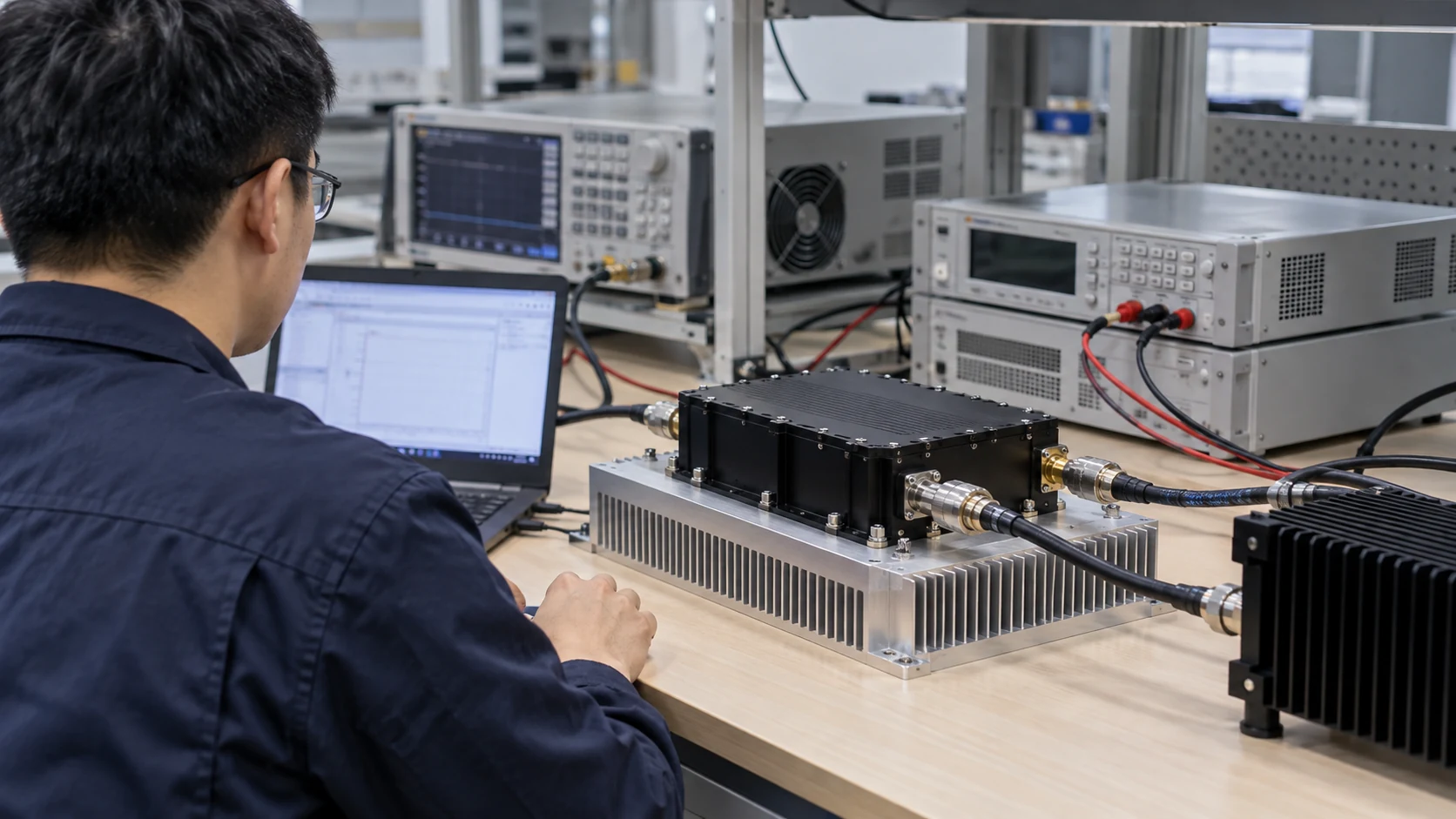
How do matching and circuit choices affect bandwidth?
Impedance matching and the implemented circuit help determine an amplifier’s frequency response, but product measurements must establish the resulting usable bandwidth. A design explanation does not substitute for a guaranteed performance range.
Outline the role of impedance matching
The transistor, matching structures, package, bias arrangement, and connections operate together; the matching-network fundamentals explain the role of impedance transformation. Changing one element can change the finished response, so a component-level claim needs supporting data at the module or system boundary being purchased.
- Identify whether evidence describes a device, module, or complete unit.
- Ask which configuration produced the published curves.
- Keep permitted load and stability conditions with the response data.
Compare implemented products rather than labels
Ask where the explanation becomes a measured result. A supplier discussing matching should be able to relate that explanation to relevant output, gain, efficiency, or load-condition evidence. The custom RF development process can frame those questions when a standard configuration leaves a requirement unresolved.
| Design factor | Product evidence to examine | Decision use |
|---|---|---|
| Matching implementation | Response across required frequencies | Confirm coverage |
| Bias and operating mode | Output and input-power conditions | Compare working points |
| Packaging and interfaces | Installed performance conditions | Assess integration constraints |
Keep a technical rationale attached to a verifiable product result. Key Takeaway: Select a demonstrated configuration rather than inferring performance from its circuit label.
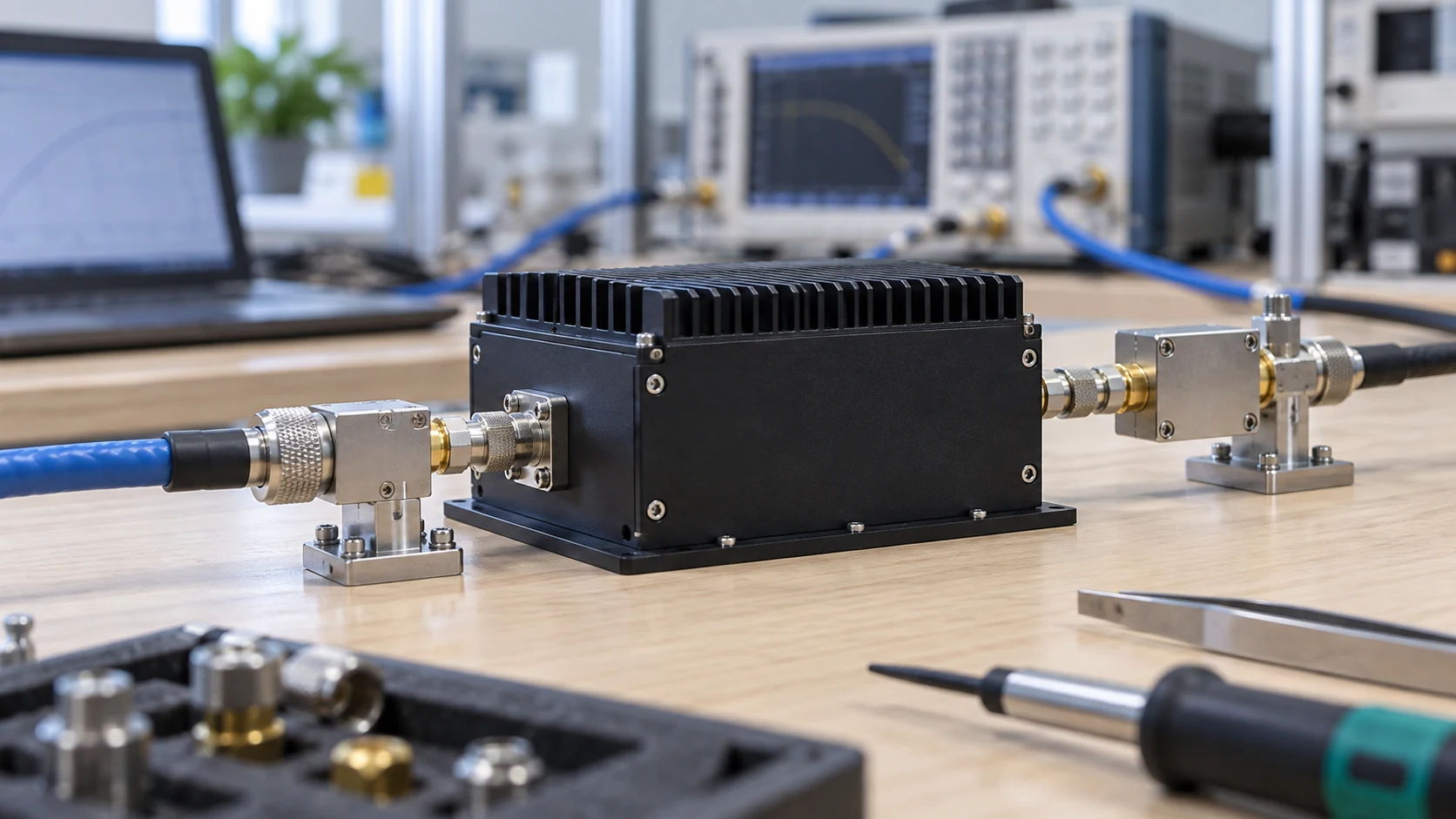
Which integration costs belong in the comparison?
Include the hardware, installation, controls, calibration, and change-management work needed to operate each candidate configuration. Compare quotations only after identifying what each supplier includes and what your team must supply.
Include hardware and installation requirements
An amplifier price may omit external supplies, cooling fixtures, mounting parts, or RF routing. Multiple narrowband paths can share some resources, but any proposed sharing needs a defined operating sequence and capacity assessment.
- List equipment supplied with each configuration.
- Identify externally supplied power, cooling, and routing hardware.
- Record rack space, access, and replacement requirements.
Include calibration and engineering work
A path also carries a maintenance workload. Record control development, acceptance testing, calibration, and the work triggered by replacing a cable or switching assembly. Use the delivery documentation checklist to establish which configuration records must remain with the equipment.
| Cost or effort | Input needed | Open question |
|---|---|---|
| Installation | Complete included-hardware list | What must the buyer provide? |
| Calibration | Defined RF paths and method | What changes require a new record? |
| Maintenance | Access and replacement procedure | What must be reverified afterward? |
Keep unknown costs visible until the responsible team supplies them. Key Takeaway: Evaluate the operating configuration and its upkeep before comparing amplifier prices.
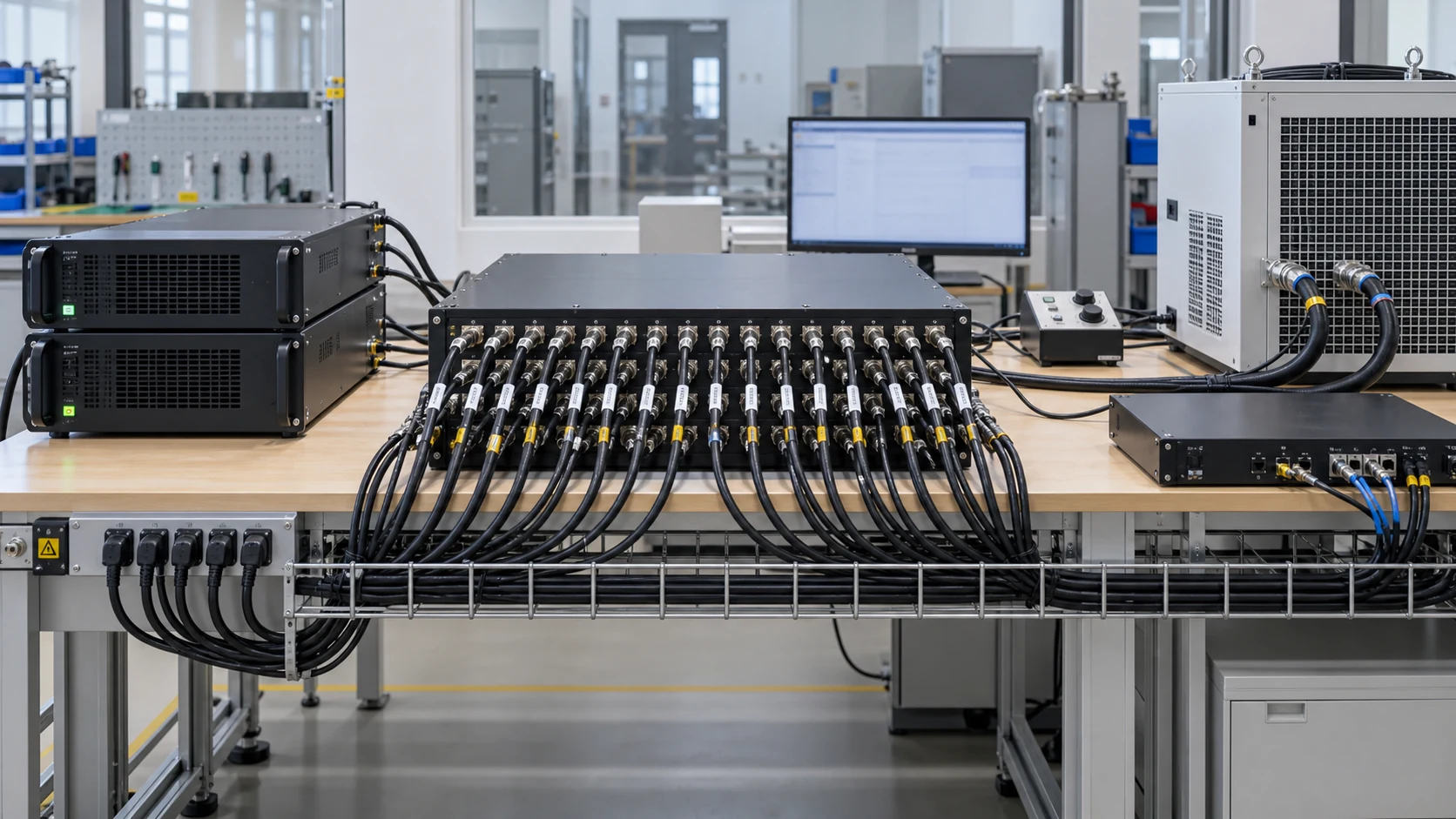
Which application conditions favor each approach?
Continuous coverage and routing constraints should direct the initial shortlist; performance tests should determine whether the shortlisted configuration qualifies. Broadband and narrowband approaches can each be suitable under different frequency plans.
Apply a frequency-plan decision matrix
Start with requirements that cannot be relaxed. A continuous sweep favors investigating uninterrupted coverage, while a small set of separately operated bands makes switched paths a reasonable candidate for evaluation.
- Identify required intervals without acceptable coverage gaps.
- State switching, settling, and simultaneous-operation constraints.
- Separate committed future frequencies from speculative expansion.
Identify claims that need a common test setup
A promising architecture still needs to pass the same test. Compare delivered output, waveform quality, recovery behavior, and thermal operation with equivalent external-path conditions. Treat missing evidence as an open qualification item rather than assigning a favorable score.
| Project condition | Candidate direction | Required check |
|---|---|---|
| Uninterrupted sweep | Investigate continuous coverage | Output and quality across the sweep |
| Separate fixed bands | Investigate selectable paths | Routing, switching, and calibration |
| Future expansion | Assess both configuration options | Actual upgrade scope and dependencies |
Use architecture preferences to narrow testing, not to bypass it. Key Takeaway: Qualification rests on common operating conditions after the frequency-plan screening.
What should a bandwidth-focused RFQ contain?
A bandwidth-focused RFQ should provide the complete frequency plan, signal bandwidth, required output, quality limits, and routing behavior. It should also define the measurement and delivery evidence needed to accept the configuration.
Provide the full frequency and signal plan
Send a requirement matrix that separates continuous coverage, discrete bands, and simultaneous signals. Attach known path losses, load conditions, and installation constraints so the proposed configuration can be assessed as a whole.
Request performance at every required operating point
CorelixRF provides amplifier product information and a contact route for discussing these requirements. Contact us with your frequency plan and identify the working points that still require supplier confirmation.
Our position is straightforward: bandwidth claims should be supported by evidence at the conditions the buyer will use. Key Takeaway: Complete the comparison with a documented configuration and an agreed verification plan.

Can I treat RF coverage and modulation bandwidth as the same?
No. RF coverage identifies where the amplifier operates; modulation bandwidth describes the occupied signal around a carrier. Specify both and request relevant performance evidence.
How do I know if band-edge power meets my requirement?
Request qualified output data at the band edges under your waveform, temperature, and load conditions. Include downstream loss when checking the required delivered power.
What’s the best way to compare one broadband unit with several PAs?
Compare complete configurations. Include selectors, controls, power, cooling, calibration, and the behavior required during path changes.
Can I assume a narrowband amplifier will use less power?
No. Compare measured electrical input at equivalent frequency, output, waveform, and system boundaries before estimating operating consumption.
How do I know which parts limit a bandwidth upgrade?
Trace every required RF path and its supporting controls. Verify filters, switches, cables, antennas, loads, and calibration requirements against the proposed frequency plan.