
An SSPA vs TWTA for satellite communication review can reveal costs that equal power ratings hide. One proposal needs more carrier backoff, while another changes cooling and maintenance. The wrong comparison can leave your ground station short of usable uplink power.
Compare complete ground-station configurations against the same carrier plan, usable-output target, and installation limits. Verify signal quality, then compare electrical input, recovery arrangements, and lifecycle costs. Spaceborne payloads need separate qualification; ground equipment data cannot establish it.
Throughout this article, any CorelixRF technical-documentation support, application review, customization path, or test-data recommendation is subject to project review, the supplied product configuration, and the project’s requirements.
Which ground-station requirements define the comparison?
The comparison begins with the ground station’s uplink band, carrier loading, output reference plane, and availability requirement. Those inputs establish the common task for both amplifier technologies.
Separate ground terminals from spaceborne payloads
Keep the application boundary explicit. Ground equipment has installation, access, power, and cooling conditions that differ from a payload in orbit. Use a ground-system integration review to connect the amplifier requirement to the actual terminal.
- Identify the amplifier’s position in the transmit chain.
- State required operating and standby modes.
- Describe the site and maintenance constraints.
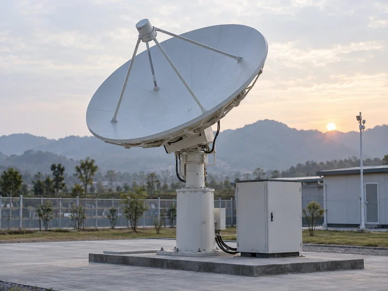
Set the uplink operating requirements
Fix the carrier plan before comparing equipment. Record frequency coverage, carrier count, signal bandwidth, and the quality criteria used to define usable output. Agree which assumptions may change during the project.
| Requirement | Common input | Decision supported |
|---|---|---|
| Uplink scope | Band and carrier plan | Candidate coverage |
| Output target | Quantity and reference plane | Power budget |
| Availability | Permitted interruption | Recovery arrangement |
An application change can invalidate a comparison made under earlier assumptions.
Key Takeaway: Give both suppliers the same ground-station operating brief before requesting a technology recommendation.
How much usable RF output does the uplink need?
The uplink needs enough output to satisfy the carrier-quality requirement and downstream power budget. Saturated output is a reference capability, not a guarantee of usable communication power.
Separate saturated output from operating output
State the output required with the intended modulation and carrier loading. Request the associated distortion results and explain any permitted linearization. A quotation should identify the actual working output rather than leaving the buyer to infer it from saturation.
- Specify average and peak quantities where applicable.
- Record the applicable output-quality limit.
- Identify any required output backoff and its reference.
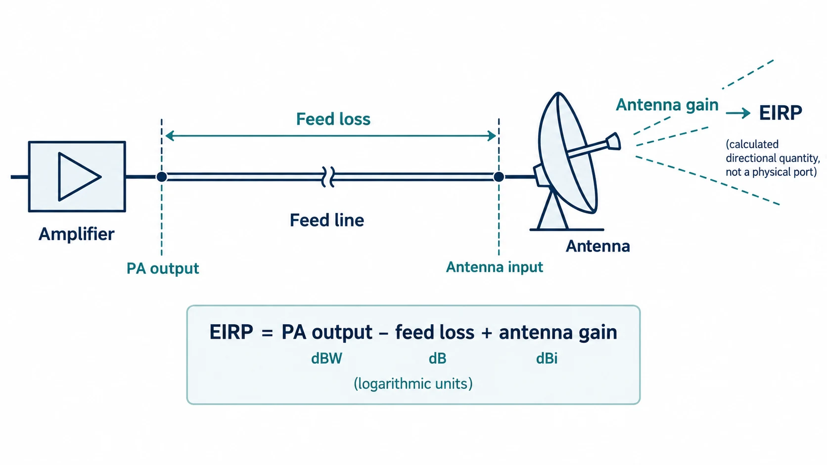
Connect amplifier output with the antenna path
Carry the power budget through the feed system. Cable, waveguide, switch, and other applicable losses sit between the amplifier and antenna. Review the amplifier-to-antenna chain so the quoted output and the antenna-input requirement refer to consistent locations.
| Power location | Required information | Check |
|---|---|---|
| PA connector | Usable operating output | Signal-quality evidence |
| Feed system | Relevant path losses | Installed configuration |
| Antenna input | Required delivered power | Complete-chain budget |
Feed loss and output backoff account for different constraints. Key Takeaway: Specify usable PA output and the downstream budget separately, keeping every power value tied to a reference plane.
How do modulation and multiple carriers affect selection?
Modulation and carrier loading affect distortion and the output level at which an amplifier can operate acceptably. Both candidates must be evaluated with an equivalent signal arrangement.
Define the carrier loading scenario
Describe the normal and limiting carrier combinations, including their relative levels and occupied bandwidth. When the source arrangement needs review, define the waveform-generation requirements together with the amplifier test.
- State the number and placement of carriers.
- Include modulation and bandwidth conditions.
- Identify processing used during the quality measurement.
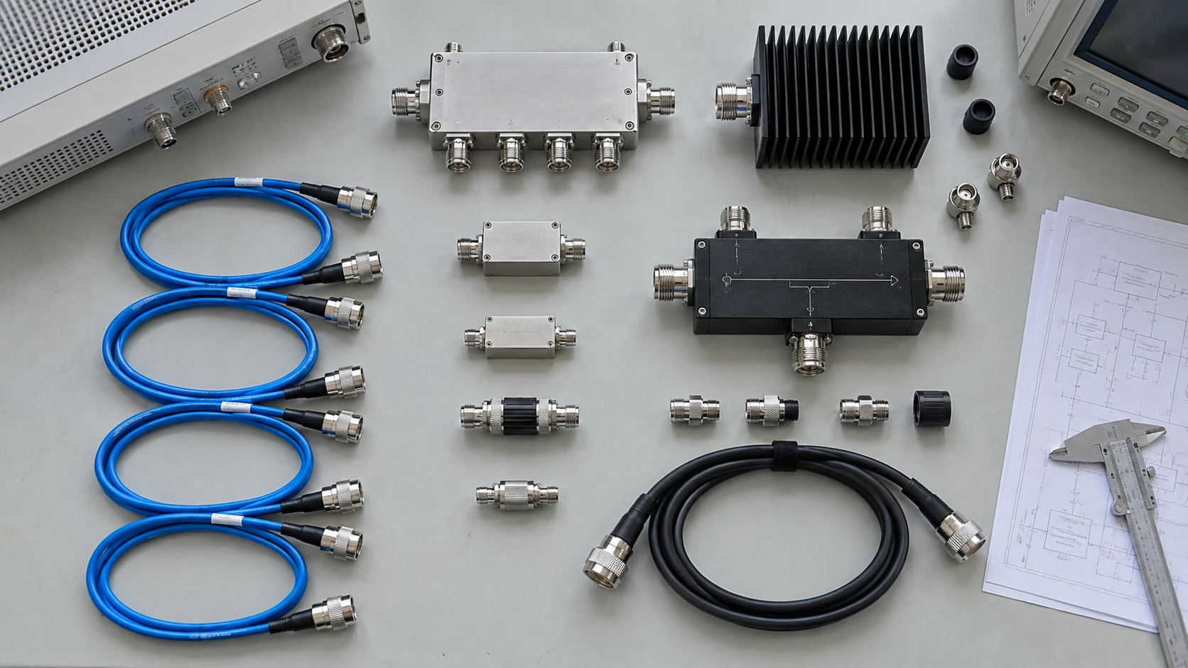
Compare distortion at the required output
Request the carrier arrangement you intend to operate. The ITU discussion of multicarrier intermodulation explains the trade-off between reducing distortion through backoff and retaining output power. It does not supply one backoff value suitable for every amplifier or carrier plan.
| Scenario | Measurement to align | Qualification question |
|---|---|---|
| Single carrier | Modulation and output | Required quality met? |
| Multiple carriers | Loading and spacing | Intermodulation acceptable? |
| Changed loading | New operating conditions | Additional test needed? |
A result from one carrier configuration may not cover another. Key Takeaway: Base the usable-output comparison on a defined carrier test, with correction settings and limits disclosed.
What differs between SSPA and TWTA systems?
SSPAs use solid-state amplifying devices, while TWTAs use a traveling-wave tube with its supporting electronics. The purchasing comparison should include equivalent complete-equipment functions.
Outline the two amplification approaches
The solid-state route may combine multiple RF stages or devices to reach the required output. A TWTA includes the tube and the power, control, and protection functions needed to operate it. Implementation choices affect the system result in both cases.
- Identify the RF amplification assembly.
- List included supplies and controls.
- Clarify external cooling and protection provisions.
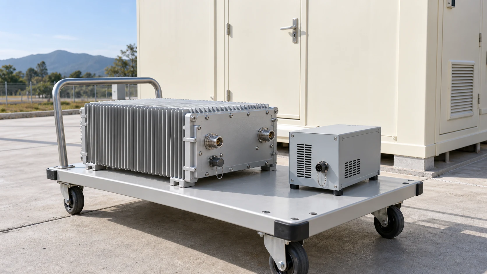
Compare equivalent equipment boundaries
Reconcile the delivered assemblies before comparing size or energy use. A module figure and a complete rack figure cannot support the same conclusion unless their boundaries are aligned. Include any separately supplied accessories in the comparison.
| Function | SSPA proposal | TWTA proposal |
|---|---|---|
| RF amplification | Identify included stages | Identify tube assembly |
| Power and control | State included equipment | State included equipment |
| Cooling and protection | Define supplied scope | Define supplied scope |
A missing support function changes both integration work and cost. Key Takeaway: Compare complete configured solutions, with external support equipment clearly listed.
How do size and cooling affect installation?
The installation must accommodate the amplifier’s physical envelope, power connections, cooling arrangement, and service access. Check these constraints at the proposed location, not only on a bench.
Review indoor, outdoor, and antenna-adjacent locations
Locate each candidate in the station layout and examine the RF path and maintenance access. An antenna-adjacent installation may change feed losses, environmental exposure, and repair procedures. These effects belong in the equipment review.
- Check space, mounting, and mass information.
- Record connection and maintenance clearances.
- Identify environmental conditions at the equipment.
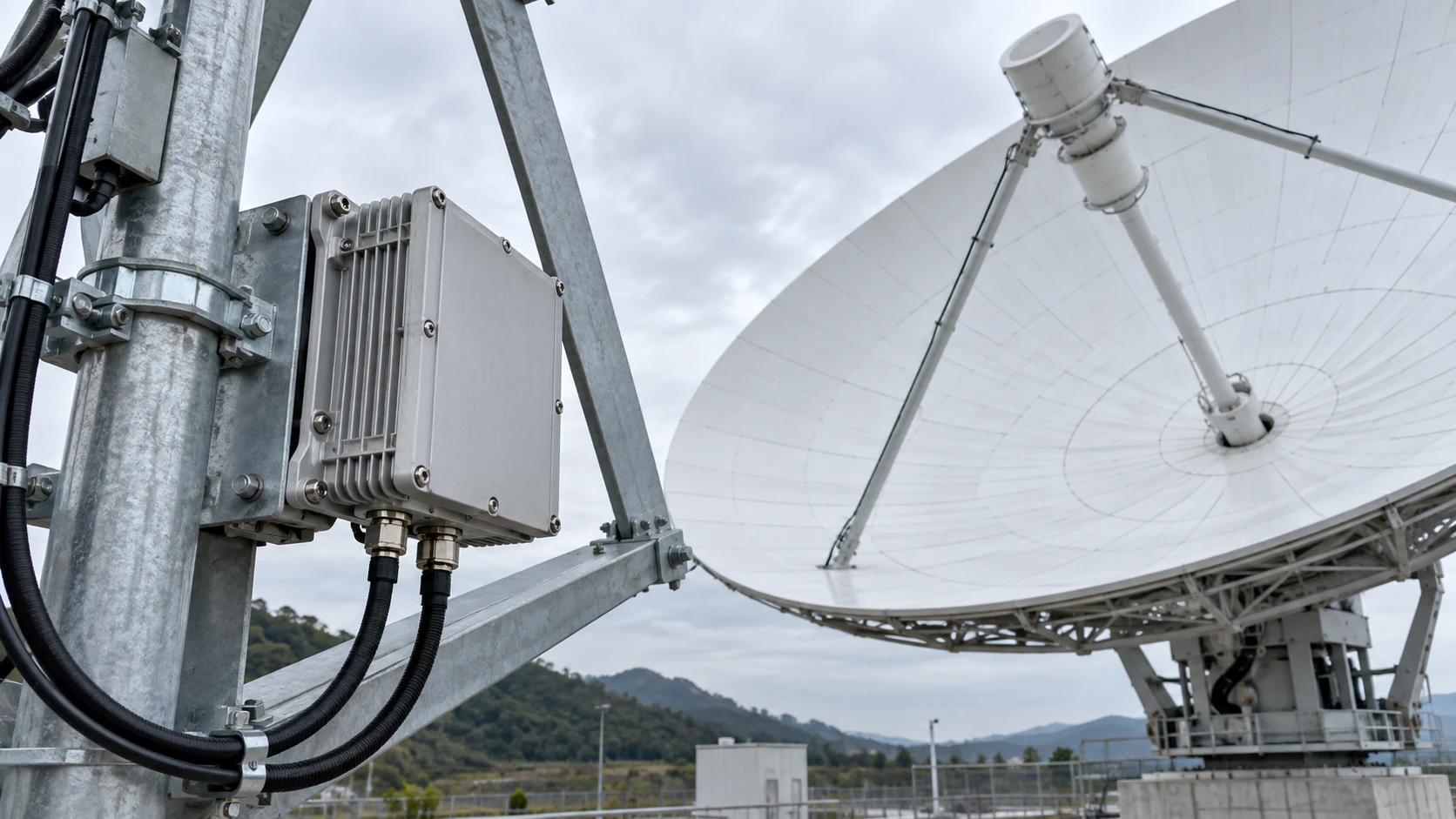
Define installation interfaces and cooling conditions
Check the interfaces under the site’s operating conditions. For a custom amplifier configuration, request drawings and support requirements before assuming it fits. Confirm what the site must provide and what the supplier includes.
| Installation item | Site constraint | Required evidence |
|---|---|---|
| Mechanical envelope | Space and access | Configuration drawing |
| Electrical input | Available supply | Operating requirements |
| Cooling boundary | Air or liquid conditions | Applicable thermal limits |
An otherwise suitable amplifier can require a substantial installation change. Key Takeaway: Complete a site-interface review before using an equipment-level advantage to select a configuration.
What determines availability and serviceability?
Availability depends on how the installed system responds to faults and how service restores operation. A semiconductor or tube label cannot establish the site’s outage risk.
Compare failure modes and recovery arrangements
Ask what happens after a relevant fault: reduced output, shutdown, redundant-path switching, or manual intervention. Where graceful degradation is claimed, request evidence of the remaining usable output and the applicable configuration.
- Identify acceptable interruption and recovery time requirements.
- Define redundant functions and switching behavior.
- State the service access and spare strategy.
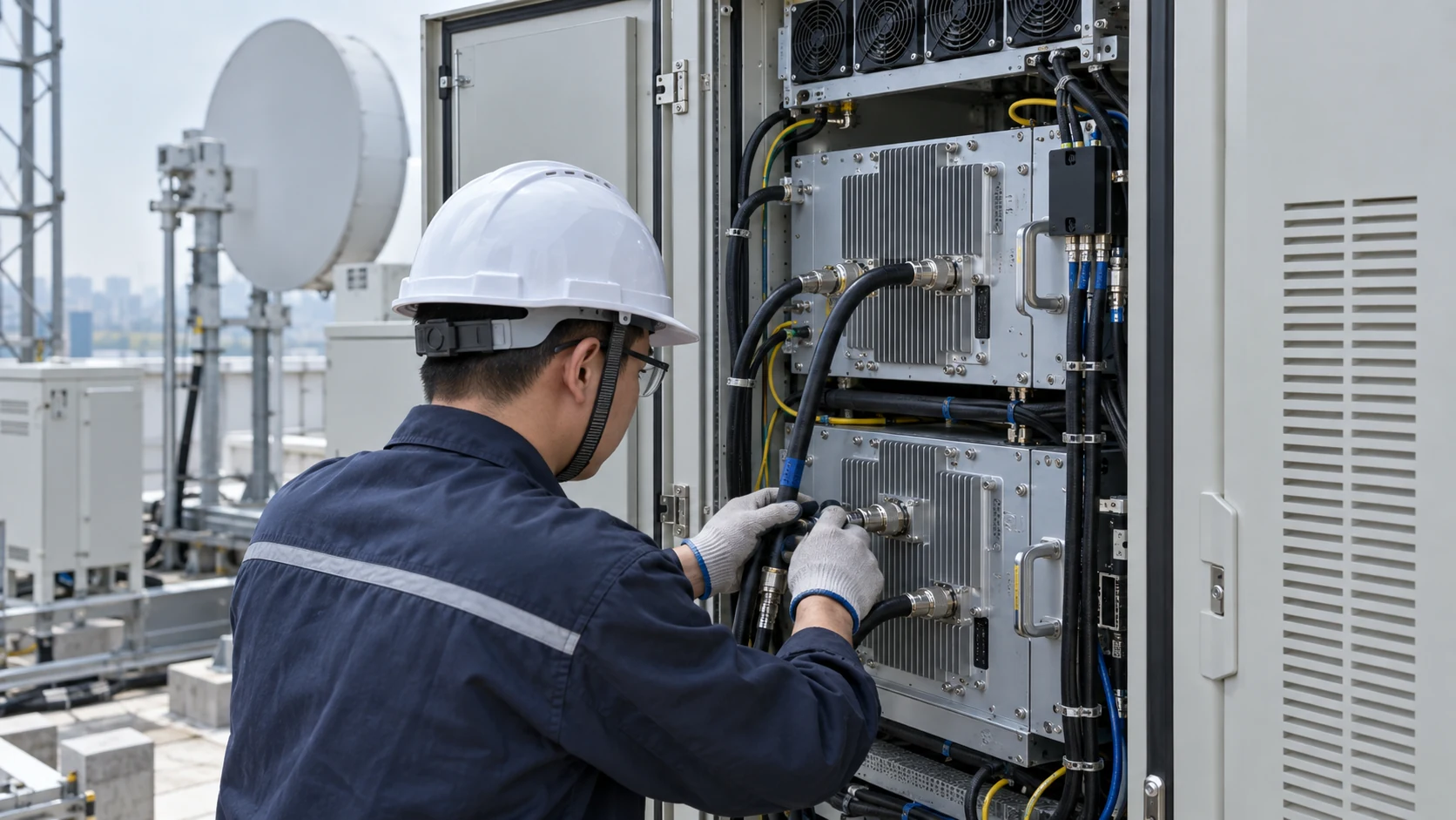
Review repair logistics and reliability assumptions
Follow the fault through to restored service. Agree the equipment documentation needed for diagnosis, configuration identification, and replacement. Keep predicted reliability metrics separate from observed field records and contractual service provisions.
| Event | System response to confirm | Recovery input |
|---|---|---|
| RF path fault | Output or switching state | Diagnostic record |
| Support-system fault | Protective behavior | Repair responsibility |
| Unit replacement | Reconfiguration requirements | Spare and test procedure |
Redundancy and service arrangements can change the consequence of an individual fault. Key Takeaway: Evaluate recovery at station level using defined events, responsibilities, and supporting records.
Which system uses less power at your operating point?
The lower-consumption system is the one with lower measured electrical input for the required usable output and duty profile. Compare identical included functions and operating states.
Compare measured electrical input
Record normal output, carrier configuration, supply boundary, and thermal conditions. A device-efficiency number cannot represent an entire system unless the omitted loads are separately accounted for. Include the time spent in each relevant state.
- Request electrical input at normal carrier output.
- Record standby and idle requirements.
- Include redundancy according to its actual operating arrangement.
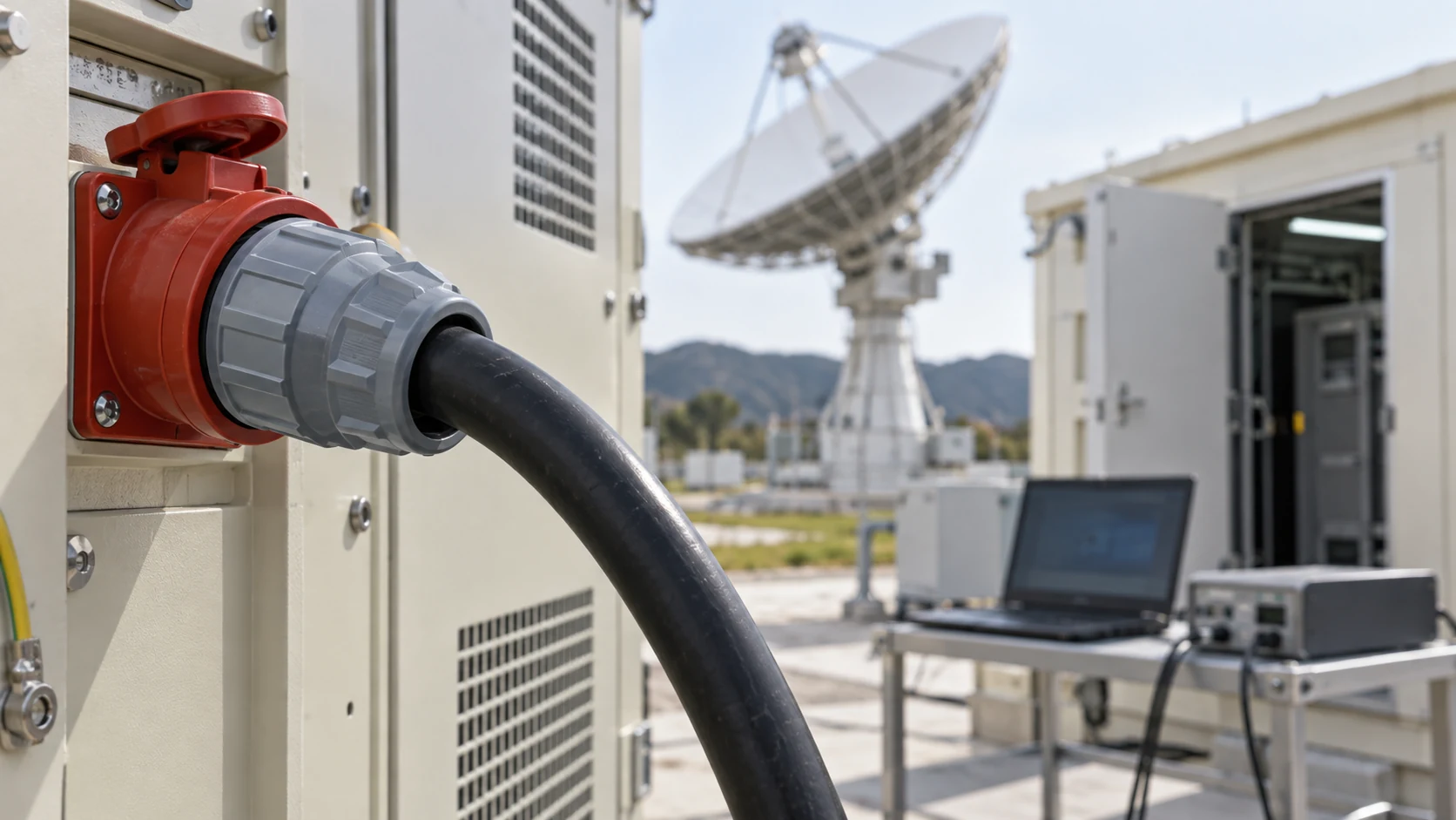
Include cooling and standby consumption
Extend the boundary to the equipment needed to keep it running. Review cooling provisions and their installation when comparing support loads. Avoid counting an auxiliary twice if it is already inside a quoted system-input measurement.
| State or load | Evidence required | Budget treatment |
|---|---|---|
| Normal transmission | Defined carrier output and input | Operating contribution |
| Standby | Actual supported mode | Time-weighted contribution |
| External cooling | Separate electrical input | Add only when excluded |
The duty profile determines which measurements drive the energy comparison. Key Takeaway: Compare measured input across the station’s operating states, with clear boundaries for auxiliaries.
How should lifecycle cost be calculated?
Lifecycle cost should combine acquisition, installation, operation, and maintenance over a common period using traceable inputs. Treat unknown costs as open assumptions rather than estimated savings presented as facts.
List acquisition and integration costs
Include supporting equipment, RF-path changes, control work, installation, and acceptance testing. A standard amplifier platform can be a configuration starting point; confirm its supplied scope before comparing it with a customized proposal.
- Reconcile included hardware and services.
- Identify site work and engineering changes.
- Separate quoted amounts from budget assumptions.
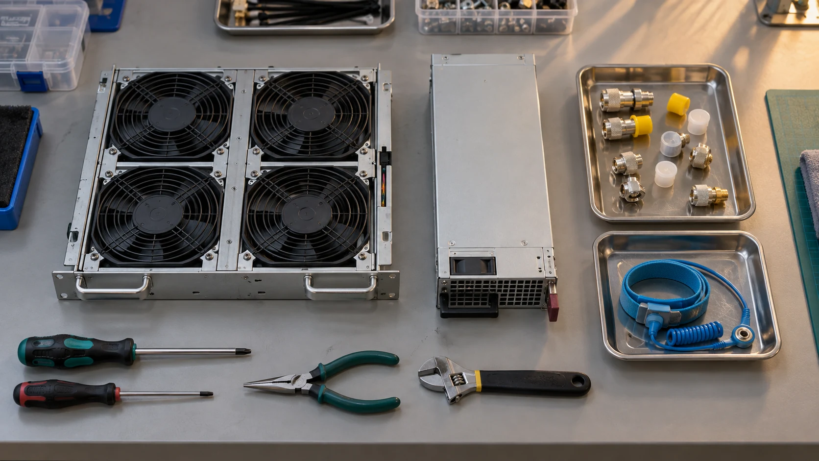
Estimate operation and maintenance from supplied inputs
Test the result against the inputs that remain uncertain. Use measured energy requirements, current tariffs, and agreed service assumptions. If downtime cost is included, state the event model and avoid presenting it as an observed failure rate.
| Cost category | Input source | Uncertainty to retain |
|---|---|---|
| Acquisition | Comparable quotations | Exclusions and options |
| Operation | Duty profile and energy rate | Future usage changes |
| Maintenance | Service and spare plan | Event frequency assumptions |
A cost ranking can change when an unquoted integration task is included. Key Takeaway: Build a transparent ownership-cost worksheet instead of asserting a universal economic winner.
Which conditions support an SSPA or TWTA shortlist?
Shortlist configurations that satisfy the same usable-output, signal-quality, installation, and recovery requirements. Compare preferences only after mandatory conditions have a supported path to acceptance.
Apply common pass criteria to both options
Use a requirement matrix with the evidence for each candidate and any missing condition. Do not offset an unresolved output or interface requirement with a favorable efficiency or price score.
- Identify mandatory operating limits.
- Record the supporting document and configuration.
- Assign action owners for unresolved evidence.
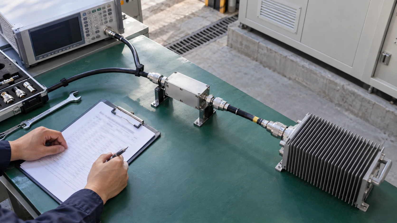
Document trade-offs without a universal winner
Use a common acceptance setup to resolve decisive differences. Specify the test data a technical buyer needs under the agreed carrier plan. Preserve conditional decisions until the required evidence is available.
| Requirement status | Meaning | Next action |
|---|---|---|
| Supported | Evidence covers the requirement | Compare remaining factors |
| Conditional | Assumptions affect acceptance | Close stated conditions |
| Unverified | Required evidence missing | Request or perform testing |
The unresolved row that can change station operation deserves priority. Key Takeaway: Make the shortlist traceable to common requirements and a defined plan for closing evidence gaps.
What should a satellite amplifier RFQ include?
A ground-station RFQ should include the carrier plan, usable-output budget, installation interfaces, availability requirements, and agreed acceptance evidence. These details make the technology comparison actionable.
Prepare a ground-station evaluation brief
Collect the latest drawings and operating assumptions in one revision-controlled package. Identify which conditions are fixed and which can be negotiated before suppliers commit to a configuration.
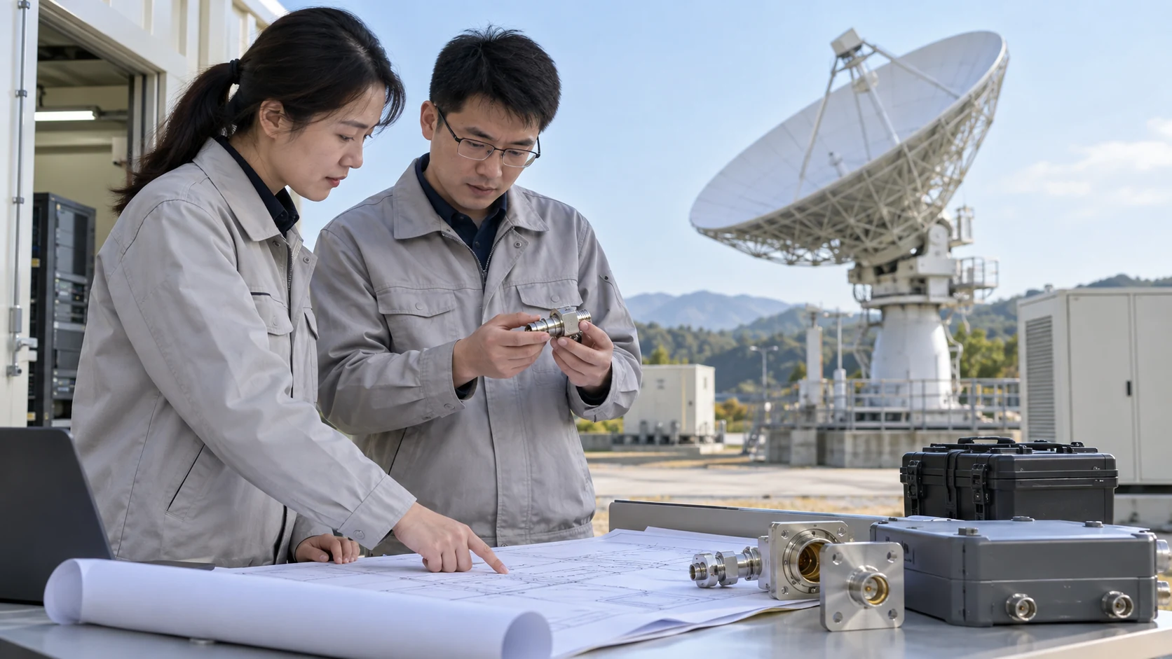
Agree a representative acceptance test
CorelixRF provides amplifier information and a route to review application requirements. Share the uplink band, carrier arrangement, output reference plane, and installation constraints when you contact us. Request a response tied to a proposed configuration and applicable records.
We favor equipment decisions that can be checked against the station’s actual operating requirements. Key Takeaway: Submit the ground-station brief and acceptance conditions together so the next review can establish a supported solution.
Can I use ground-station data to choose a spaceborne amplifier?
No, not as qualification evidence. Payload conditions and qualification requirements need their own assessment and applicable records.
How do I know if two amplifiers provide equal usable carrier power?
Compare output at the same reference plane, carrier loading, quality limit, and thermal condition. Saturated ratings alone are insufficient.
What’s the best way to compare power use at normal output?
Measure equivalent complete configurations with the intended carrier plan and operating profile. Include external auxiliaries only when they are outside the stated boundary.
Can I remove redundancy when replacing a TWTA with an SSPA?
Only after reassessing station availability and recovery requirements. Technology alone does not establish acceptable outage behavior.
How do I know which interfaces need review before a replacement?
Compare RF, electrical, control, cooling, mechanical, and service interfaces. Assign a validation task to each material change.