
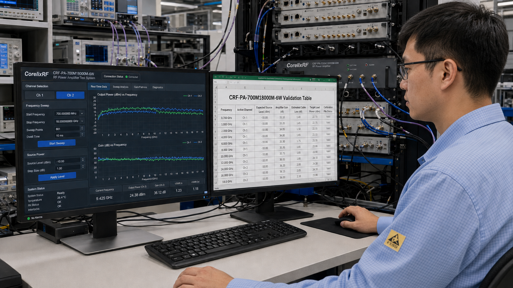
This application note explains how to plan a dual-channel broadband RF power amplifier path around the CorelixRF CRF-PA-700M18000M-6W. The amplifier is specified for Channel 1 from 0.7-2 GHz and Channel 2 from 2-18 GHz, with 6 W rated output power, SMA-Female RF input and output connectors, and a 3U rack-mount form factor.
Unlike a product update, this article is procedural. It treats the amplifier as one block in a wider signal chain and walks through the decisions that prevent integration problems. It is intended for RF engineers building broadband EMC support paths, receiver blocking tests, communication hardware benches, or RF interference system-level evaluations.
Objective
The objective is to create a repeatable test path that uses the correct amplifier channel, reaches the required power at the load, protects the amplifier from avoidable mismatch risk, and gives the operator a clear sequence for setup and shutdown. The 6 W rating should be evaluated against the load requirement, not against a generic amplifier category.
Procedure
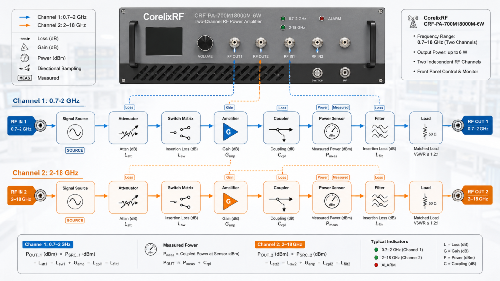
- Draw the RF path from signal source to load, including source, attenuator, switch, active channel, coupler, sensor, filter, cable, fixture, antenna, or termination.
- Separate Channel 1 and Channel 2 in the drawing because 0.7-2 GHz and 2-18 GHz paths can have different loss, calibration, and switching behavior.
- Calculate path loss at low, middle, and high frequencies. Do not use one cable-loss value for the entire 700 MHz-18 GHz span.
- Confirm the required power at the load and compare it against the 6 W amplifier output rating with margin.
- Define the waveform, duty cycle, dwell time, and software sequence before requesting a quotation.
Signal Chain Example
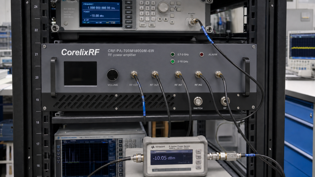
A practical chain may start with a signal generator or SDR source, pass through a programmable attenuator, route through a switch matrix, enter the selected amplifier channel, then feed a directional coupler and power sensor before reaching the test fixture or antenna. In that chain, each block needs a known loss value. The amplifier is only one part of the delivered-power calculation.
For automated work, the software should select the channel, confirm the switch state, set the source level, enable RF drive, observe amplifier status, begin measurement, and define shutdown behavior. This is where a custom RF amplifier review can help if the standard control behavior does not match the test software.
Design Notes
The datasheet positions the amplifier as a GaN SSPA for test and measurement instrumentation, communication systems, RF interference or EW system-level testing, and aerospace control. Those applications can involve CW, stepped, swept, modulated, or duty-cycled operation. The RFQ should state the real operating profile and not just the desired frequency range.
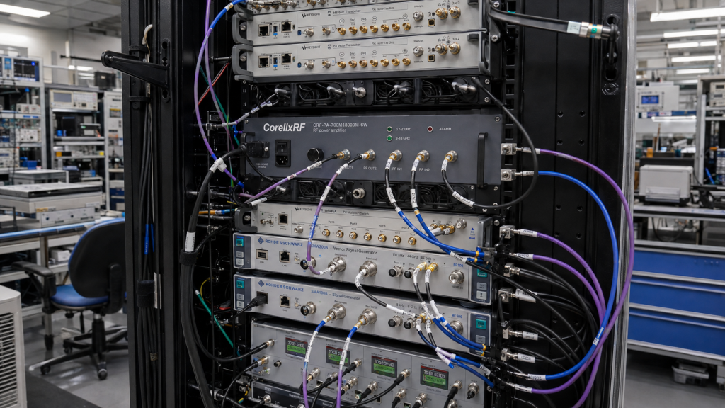
Mechanical planning matters because the amplifier is rack-mounted. Define airflow, rack depth, cable bend radius, front or rear panel routing, and service access. If the system also includes sources, switches, sensors, or monitoring equipment, the rack layout should be reviewed as one assembly.
Comparison Guidance
CRF-PA-700M18000M-6W is relevant when frequency reach matters more than high output power. If the project requires tens or hundreds of watts, another RF power amplifier may be better. If the project is mostly below 1 GHz and power is the priority, an EMC RF amplifier may be a stronger fit.
Teams still defining requirements can compare options through the CorelixRF product range and supporting RF application articles. The strongest RFQ includes a block diagram and frequency-specific power budget.
Application Note Result
A good result is a table showing frequency, selected channel, source level, path loss, target load power, calibration file, and shutdown condition. That table becomes the bridge between the datasheet and the lab procedure. It also makes the amplifier setup repeatable for multiple operators.
Validation Table to Create Before Testing
The application note should produce a validation table before any hardware is connected. Include columns for frequency, active channel, expected source level, amplifier gain assumption, estimated cable loss, coupler loss, filter loss, target load power, calibration file, and shutdown condition. This table makes the setup repeatable and gives technicians a clear record of how the amplifier is intended to be used.
The table should include at least one frequency in Channel 1 and several points in Channel 2 because microwave losses rise quickly. If the system will operate near 18 GHz, include that high-end case in the review. A design that works at 1 GHz may not have the same margin at the top of the band.
Expected Output of the Application Note
The final output is not only a model choice. It is a documented test path with known loss, known channel states, defined source limits, and a safe operating sequence. That documentation helps CorelixRF review the RFQ and helps the lab avoid setup differences between operators.
The same application note can be reused when the bench changes. If the source, cable set, coupler, antenna, or fixture is replaced, update the table and recalculate the power budget. That keeps the amplifier selection tied to measurable conditions instead of memory or assumptions.
FAQ
What are the two channels of CRF-PA-700M18000M-6W?
Channel 1 covers 0.7-2 GHz and Channel 2 covers 2-18 GHz.
What output power is specified?
The rated RF output power is 6 W.
Why should channels be documented separately?
The two paths can have different loss, calibration, switching, and control requirements.
Can it support EMC-related work?
It can be reviewed for broadband EMC support paths when system losses, duty cycle, and output requirement match.