
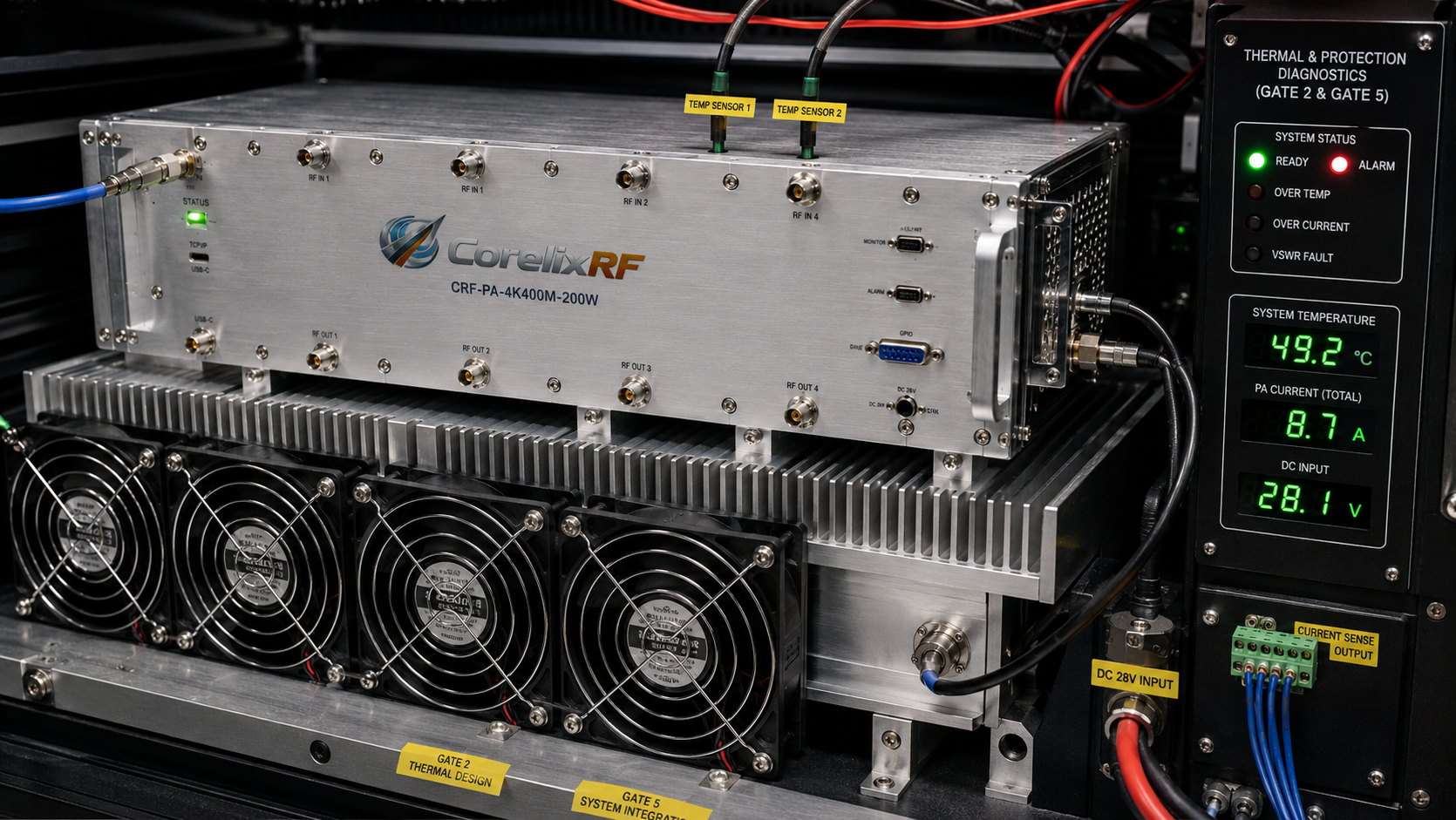
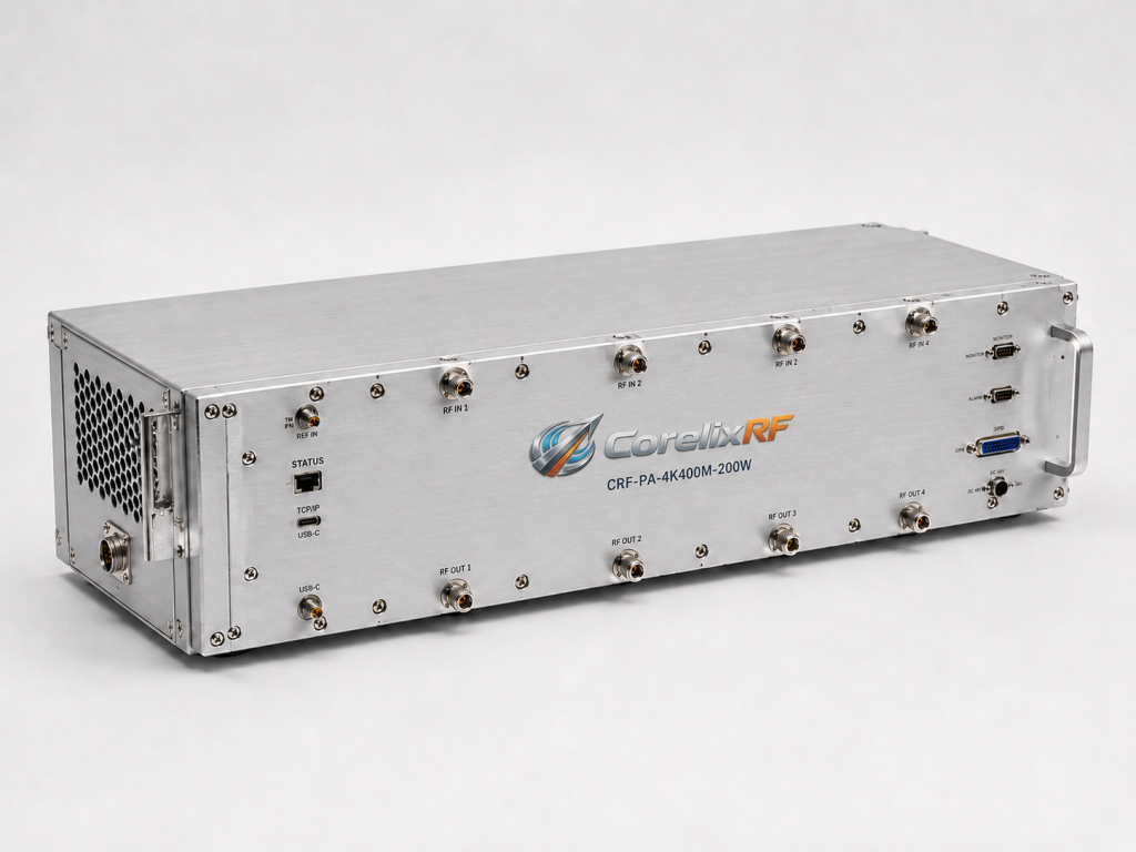
Before a low-frequency amplifier is released into a lab or production test system, it needs more than a datasheet review. The CorelixRF CRF-PA-4K400M-200W is specified as a 4 kHz-400 MHz LDMOS RF power amplifier with at least 200 W saturated output power, 53 dB minimum small-signal gain, SMA-F input, N-F output, and a 329.5 x 104.8 x 61 mm module configuration.
This article is written as a test-readiness checklist. The format is deliberately operational: each section is a gate that engineering, manufacturing, or lab operations can check before the amplifier is integrated into a fixture, rack, or EMC test path.
Gate 1: Frequency Coverage
- Confirm every required test frequency is inside 4 kHz-400 MHz.
- Separate must-have frequencies from future expansion frequencies.
- If the roadmap extends above 400 MHz, compare this model with a broadband RF power amplifier.
Gate 2: Power and Load
- Start from required delivered power, not amplifier output power.
- Include cable loss, fixture loss, coupler loss, and mismatch uncertainty.
- Document whether the load is a 50 ohm termination, coupling fixture, antenna, or project-specific device.
The datasheet gives the amplifier output class, but low-frequency systems can create complex load behavior. A 200 W amplifier may be suitable for one fixture and poorly matched to another. The RFQ should include the worst-case load condition so CorelixRF can review practical margin.
Gate 3: Drive Level and Gain
- Check source output against 0 dBm maximum input power.
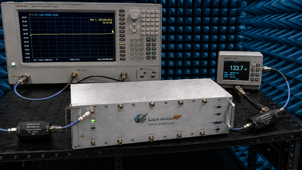
- Use the 53 dB minimum gain value in the link budget.
- Confirm whether attenuation, gain control, or external driver stages are needed.
Gate 4: Mechanical Build
The compact module footprint is useful only if mounting and heat removal are designed early. Define the mounting surface, heat sink, airflow, grounding, cable routing, connector strain relief, and service access. These decisions should be complete before drawings are frozen.
Gate 5: Diagnostics and Protection
The datasheet references temperature and current diagnostics, alarm protection, and project-ready control interfaces. For a manufacturing or lab environment, those features influence acceptance testing and daily operation. Decide which status signals must be visible to the operator and which fault conditions must shut down the test.
Gate 6: Calibration and Evidence
Document whether the system is controlled by forward power, delivered power, fixture voltage, or field-probe feedback. Acceptance evidence may include output-power data at representative frequencies, gain-flatness checks, harmonic behavior, spurious output, connector inspection, and alarm-function confirmation. Put the expected data format in the RFQ.
Pass/Fail Summary
The CRF-PA-4K400M-200W is a strong candidate when the project needs a low-frequency EMC RF amplifier with meaningful output power and a defined module footprint. It is not the right choice if the system cannot define load impedance, duty cycle, cooling, or acceptance evidence.
For adjacent product review, compare CorelixRF’s RF amplifier product range, related technical articles, and project-specific custom RF amplifier options. This checklist helps keep the decision tied to test readiness rather than headline wattage.
RFQ Checklist
Send frequency range, delivered power target, waveform, modulation, duty cycle, dwell time, impedance environment, expected VSWR, input drive level, DC power plan, cooling method, mounting constraints, control interface needs, protection requirements, and acceptance-test expectations.
Operator Checklist
- Confirm the amplifier is mounted to the planned heat path.
- Inspect SMA-F input and N-F output connector condition before connection.
- Confirm the load or fixture is connected before RF drive is enabled.
- Check source output level against the amplifier input limit.
- Record representative output-power and gain results during incoming inspection.
This operational layer is what separates a real test-readiness article from a generic selection guide. The amplifier can meet its headline specification and still cause delays if operators lack a repeatable installation and inspection procedure. A checklist makes those human steps visible.
Documentation Package
For a production or lab environment, ask what documentation can be supplied for project review. Useful items may include final mechanical drawing, interface description, available test data, connector information, recommended cooling notes, and alarm or control behavior. These records support acceptance testing and long-term maintenance.
Service Readiness Gate
Service readiness should be checked before the amplifier is enclosed in a larger system. A technician should be able to identify the RF input, RF output, control connector, power interface, heat-sink surface, and alarm path without disassembling unrelated equipment. If the amplifier is difficult to access, routine inspection and troubleshooting become slower.
For long-term use, record the installation orientation, cooling method, torque practice for RF connectors, and any limits on repeated connection cycles. Low-frequency systems can still suffer from poor connector handling, loose grounding, or undocumented fixture changes. Adding these checks makes the article read like a real manufacturing and test document rather than an SEO rewrite.
Final Lab Sign-Off
The last gate is sign-off ownership. Engineering should approve the RF limits, operations should approve the installation procedure, and purchasing should confirm that required documentation is named in the order. When all three groups agree, the amplifier is less likely to become a late-stage integration issue.
FAQ
What frequency range does CRF-PA-4K400M-200W cover?
The datasheet lists 4 kHz-400 MHz operation.
How much output power is specified?
The listed saturated output power is at least 200 W.
What technology is used?
The datasheet identifies the amplifier as an LDMOS solid-state power amplifier.
Why use a checklist format?
A checklist helps confirm frequency, power, load, cooling, control, and acceptance evidence before integration.