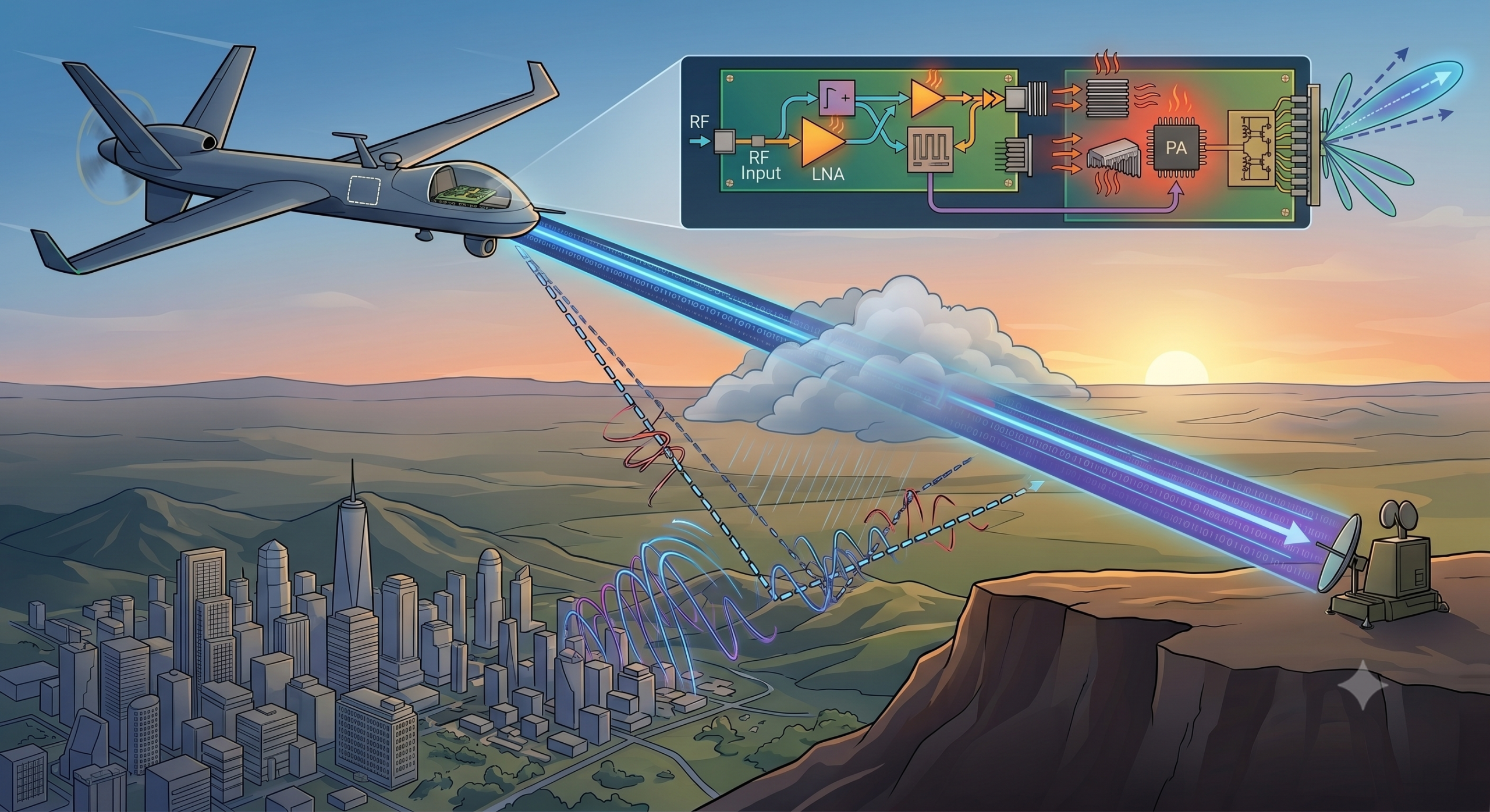
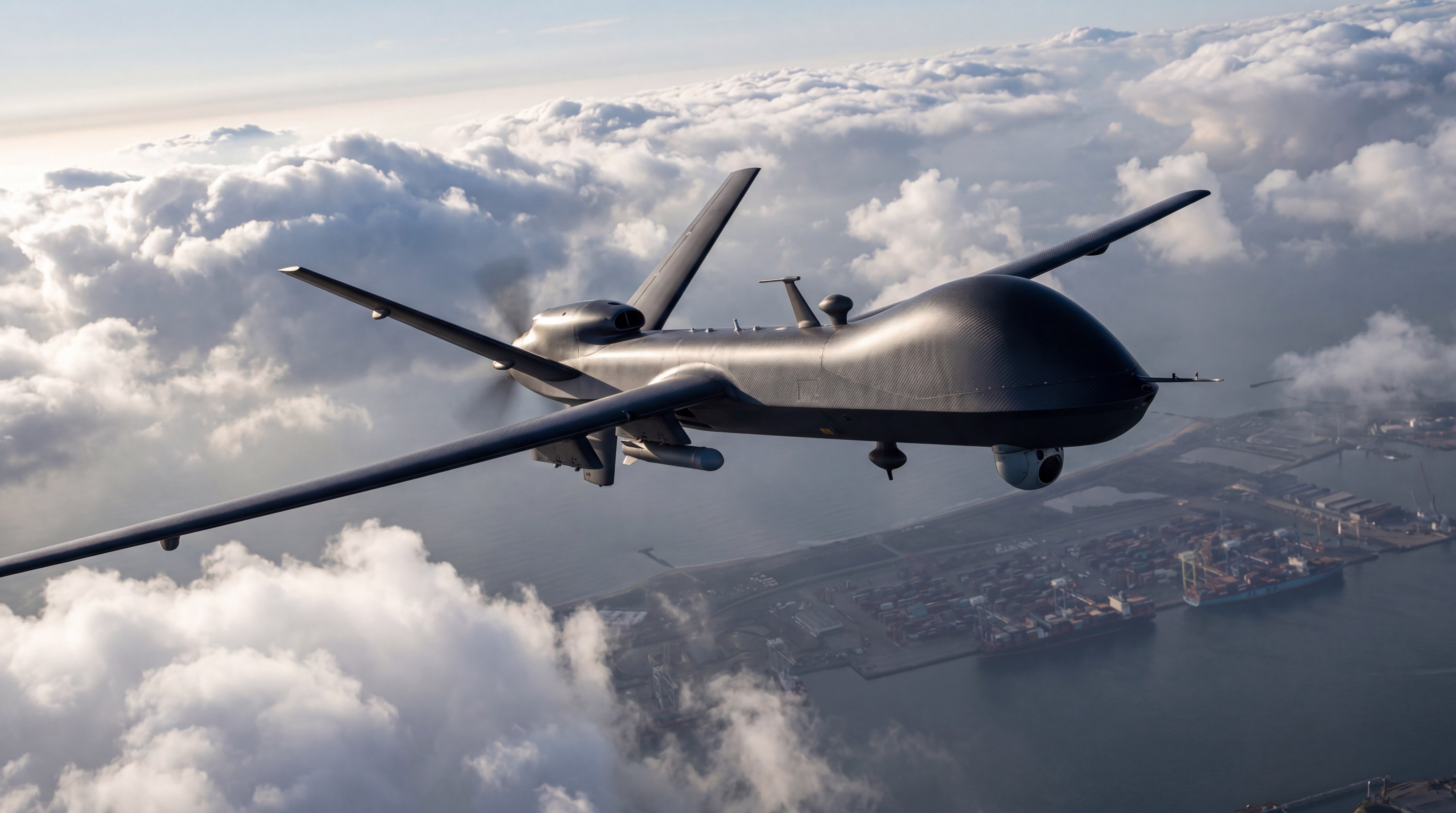
Yes, amplifiers and attenuators are absolutely critical to UAV link optimization because they actively balance signal strength, prevent receiver saturation, and maximize transmission range under highly volatile flight conditions. Imagine operating an unmanned aerial vehicle (UAV) during a critical beyond visual line of sight (BVLOS) mission, only to experience sudden telemetry dropouts. A dropped command and control (C2) link can lead to catastrophic airframe loss, ruined payloads, and severe regulatory non-compliance. You can secure robust connectivity by designing an optimized RF front-end. By integrating premium Amplifiers and Attenuators into your communication chain, you ensure stable, high-speed telemetry regardless of altitude or environmental interference.
Why does UAV link budget management fail so often?
UAV link budget management frequently fails because of dynamic physical changes during flight, such as path loss and multipath interference. As your aircraft changes altitude, orientation, and distance from the ground control station, the signal environment changes unpredictably. Standard pre-configured transceivers cannot handle these variations alone, which is why utilizing specialized Amplifiers and Attenuators is so crucial. Without active power regulation, you risk complete signal loss during complex maneuvers.
What is the impact of free space path loss?
Free space path loss causes signal power to decrease exponentially as your drone flies farther away. As distance doubles, your received signal power drops by six decibels, weakening the command link.
Think about it:
- High-altitude missions compound this attenuation over long line-of-sight paths.
- Severe weather conditions introduce sudden rain fade that quickly absorbs microwave energy.
- Obstacles along the flight path block the primary Fresnel zone and degrade signal quality.
You must design a system that can withstand these severe physical challenges. Proper gain styling ensures that your payload data gets through.
How does multipath interference degrade your link?
Multipath interference degrades your link by causing phase cancellation when reflected signals arrive at the receiver. This occurs when waves bounce off ground terrain or buildings and recombine destructively.
Here is the real catch:
- Ground reflections create out-of-phase signals that neutralize your carrier wave.
- Urban canyon environments generate severe scattering and signal degradation.
- High-velocity maneuvers trigger Doppler shifts that shift the carrier frequency.
Key Takeaway: Understanding how path loss and multipath reflections degrade your signal allows you to implement robust hardware margins that protect flight telemetry.
| Challenge | Primary Physical Mechanism | Operational Impact on UAV |
|---|---|---|
| Path Loss | Signal energy dispersion over distance | Telemetry dropouts at extreme ranges |
| Multipath Interference | Ground reflections and phase cancellation | Signal fading and high bit error rates |
The table above illustrates how physical flight challenges directly threaten your communications integrity, highlighting why proactive signal balancing is necessary.
How do active and passive components interact here?
Active and passive RF components interact dynamically to maintain optimal signal levels and prevent system oscillation. In a high-performance flight system, active components boost weak waves while passive components damp down excessive energy. Implementing a balanced combination of Amplifiers and Attenuators ensures your transceiver operates within its linear region. This cooperative architecture prevents hardware damage and stops self-interference from ruining your mission.
What is the benefit of gain styling?
Gain styling allows you to distribute amplification and attenuation across the RF chain to optimize system noise figure. This technique keeps your signals well above the noise floor without overloading intermediate stages.
But wait, there is more:
- Cascaded noise figures are minimized when the first stage has high gain.
- Intermediate attenuation prevents high-power amplifiers from driving stages into compression.
- Well-staged systems maintain linear performance across the entire temperature range.
You can achieve reliable communications by modeling the entire signal path step-by-step. This structural control protects your system against unexpected atmospheric changes.
Can active and passive parts work together?
Active and passive parts work together by stabilizing output impedance and absorbing reflected energy. When your transmitter encounters fluctuating antenna impedance during banking maneuvers, passive pads absorb the harmful reflections.
Let’s look closer:
- Passive attenuators provide excellent isolation between active gain blocks.
- Amplifiers supply the raw power needed to overcome cable and atmospheric loss.
- Combined networks prevent unwanted self-oscillation in high-gain transceivers.
Key Takeaway: Coordinating active gain blocks with passive attenuation pads ensures your RF front-end remains stable and linear under severe load changes.
| Component Type | Primary Operational Function | Critical Role in UAV Systems |
|---|---|---|
| Active Amplifiers | Increases weak RF signal amplitude | Extends transmission range and overcomes path loss |
| Passive Attenuators | Reduces excessive signal power levels | Prevents receiver blinding and stage oscillation |
The comparative matrix above shows how pairing active and passive elements stabilizes your system, demonstrating why they must be used in tandem.
When should you prioritize RF signal amplification?
You should prioritize RF signal amplification when your system must overcome extreme propagation distances or when the receiver noise floor threatens to swallow your telemetry. Long-range military and industrial drones require a high effective isotropic radiated power to maintain connection lock. Integrating high-performance Amplifiers and Attenuators helps you achieve this power boost safely. Without adequate amplification, your high-bandwidth video streams will suffer from frequent frame drops.
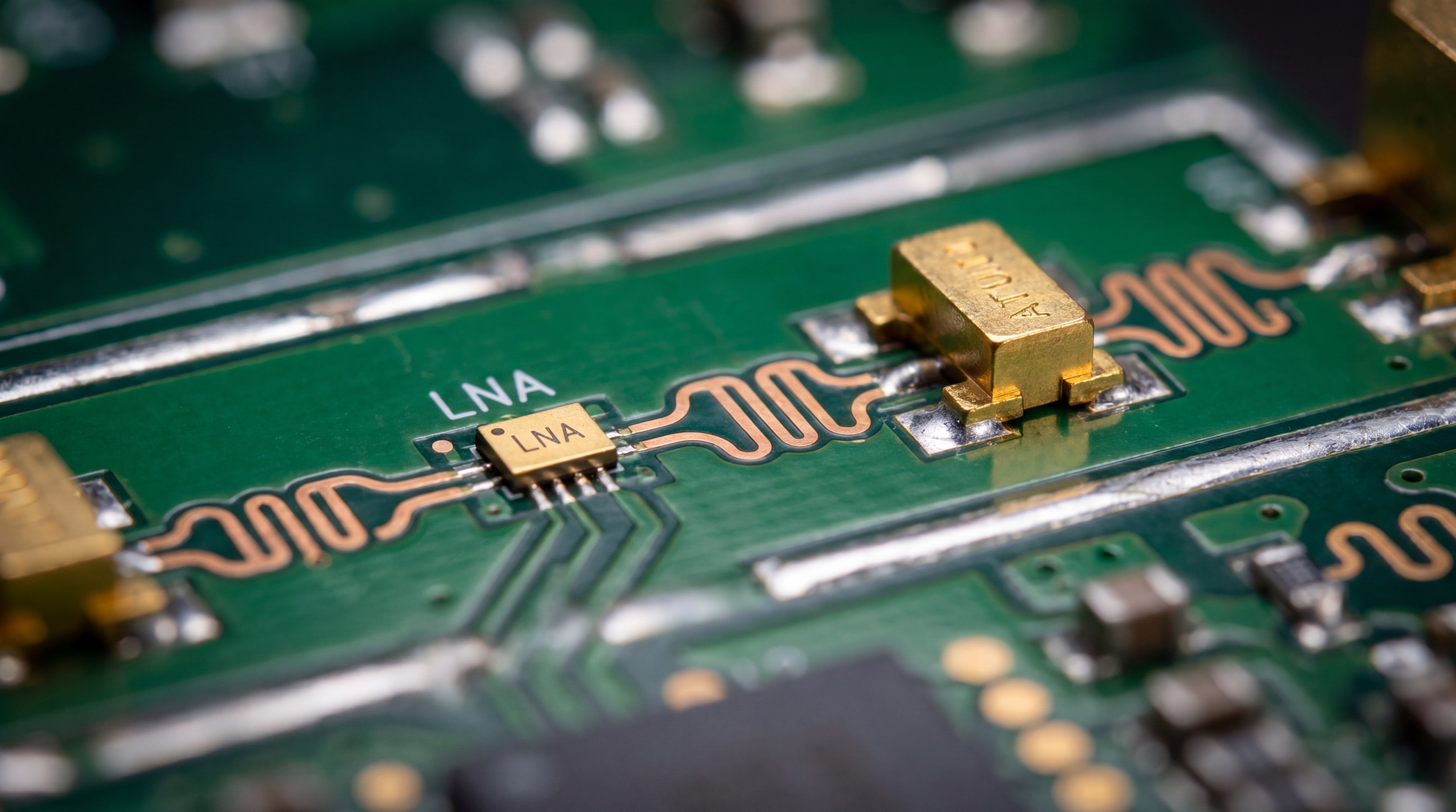
Why are Low-Noise Amplifiers critical on the receiver?
Low-noise amplifiers are critical on the receiver because they establish the noise figure for your entire downstream system. Placing an LNA right at the antenna feed minimizes the impact of coaxial cable losses.
Here is the real catch:
- First-stage gain overrides the noise contribution of all subsequent components.
- High-sensitivity LNAs allow you to detect weak uplink command signals.
- Proper LNA selection prevents adjacent-channel noise from drowning out telemetry.
You must choose an LNA with a very low noise figure and a high third-order intercept point. This balance keeps your incoming data clean and readable.
How do power amplifiers extend transmitter range?
Power amplifiers extend transmitter range by boosting output signal energy to overcome free space path loss. This ensures your ground control station can receive high-definition sensor data from miles away.
Think about it:
- Solid-state power amplifiers deliver consistent wattage across wide bandwidths.
- GaN-based active stages offer the highest power density for weight-constrained drones.
- Amplified signals slice through atmospheric attenuation and light foliage easily.
Key Takeaway: Prioritizing amplification at key stages in your RF path ensures that your drone maintains high-speed communication over extreme operational distances.
| Amplifier Type | Key Metric to Monitor | Main System Location | Primary Benefit |
|---|---|---|---|
| Low-Noise Amplifier | Noise Figure (NF) | Receiver Antenna Feed | Lowers system noise floor |
| Power Amplifier | Output Power ($P_{1dB}$) | Transmitter Output | Maximizes broadcast range |
The table above breaks down the distinct roles of transmitter and receiver amplifiers, illustrating how they work together to secure your link.
Where do attenuators prevent receiver saturation?
Attenuators prevent receiver saturation in the intermediate and downconversion stages of your RF front-end where incoming power can exceed component damage limits. When your UAV flies very close to the ground control antenna, the received signal power spikes dramatically. Managing these close-range signals requires a balance of Amplifiers and Attenuators to protect sensitive mixer diodes. Without passive damping, your receiver will blind itself and fail to decode incoming commands.
Why does close-range flight risk receiver damage?
Close-range flight risks receiver damage because the intense electromagnetic field can overload delicate low-power components. When your drone loiters near the high-power ground transmitter, signal power exceeds safe levels.
Shocking as it sounds:
- Overdriven mixers enter hard compression and generate massive harmonic distortion.
- Excessive voltage can permanently burn out sensitive receiver semiconductor junctions.
- Blinded analog-to-digital converters experience severe clipping and data loss.
You can prevent this physical damage by inserting a dedicated inline attenuation pad. This safeguard ensures your electronics stay fully operational during landing sequences.
How do step attenuators manage variable distance?
Step attenuators manage variable distance by dynamically switching resistance values as your drone moves closer or farther. This adjustability allows you to maintain a constant signal level at the demodulator.
Let’s get right to the point:
- Fixed pads provide static, highly reliable power reduction for known levels.
- Digital step attenuators adjust in discrete decibel steps via onboard logic.
- Voltage-variable models allow continuous analog tuning for seamless power leveling.
Key Takeaway: Deploying attenuators at critical points in your receiver chain shields sensitive circuits from power spikes and guarantees signal linearity.
| Attenuator Type | Adjustment Mechanism | Best Use Case | Operational Limitation |
|---|---|---|---|
| Fixed Attenuator | Resistive Pad Network | Constant high-power protection | Cannot adapt to changing range |
| Digital Step Attenuator | Switched IC Paths | Real-time software control | Introduces minor switching noise |
The table above compares fixed and digital attenuators, highlighting how to select the right device for your specific operational range.
How do these components optimize dynamic range?
These components optimize dynamic range by keeping your signal levels perfectly balanced between the thermal noise floor and the receiver compression threshold. Maximizing the spurious-free dynamic range (SFDR) requires a careful deployment of both gain and attenuation. By utilizing high-quality Amplifiers and Attenuators, you can confidently process both faint and strong signals simultaneously. This dual capability is crucial when flying through busy airspace with multiple radio sources.
How do you achieve the ideal signal-to-noise ratio?
Achieving the ideal signal-to-noise ratio requires you to boost weak carriers while suppressing background atmospheric noise. If you over-amplify, you raise the noise floor along with your target signal.
Think about it:
- Extreme gain amplifies thermal noise and degrades signal intelligibility.
- Strategic attenuation keeps your active devices working in their linear zone.
- The ideal balance maximizes data throughput and reduces packet retransmissions.
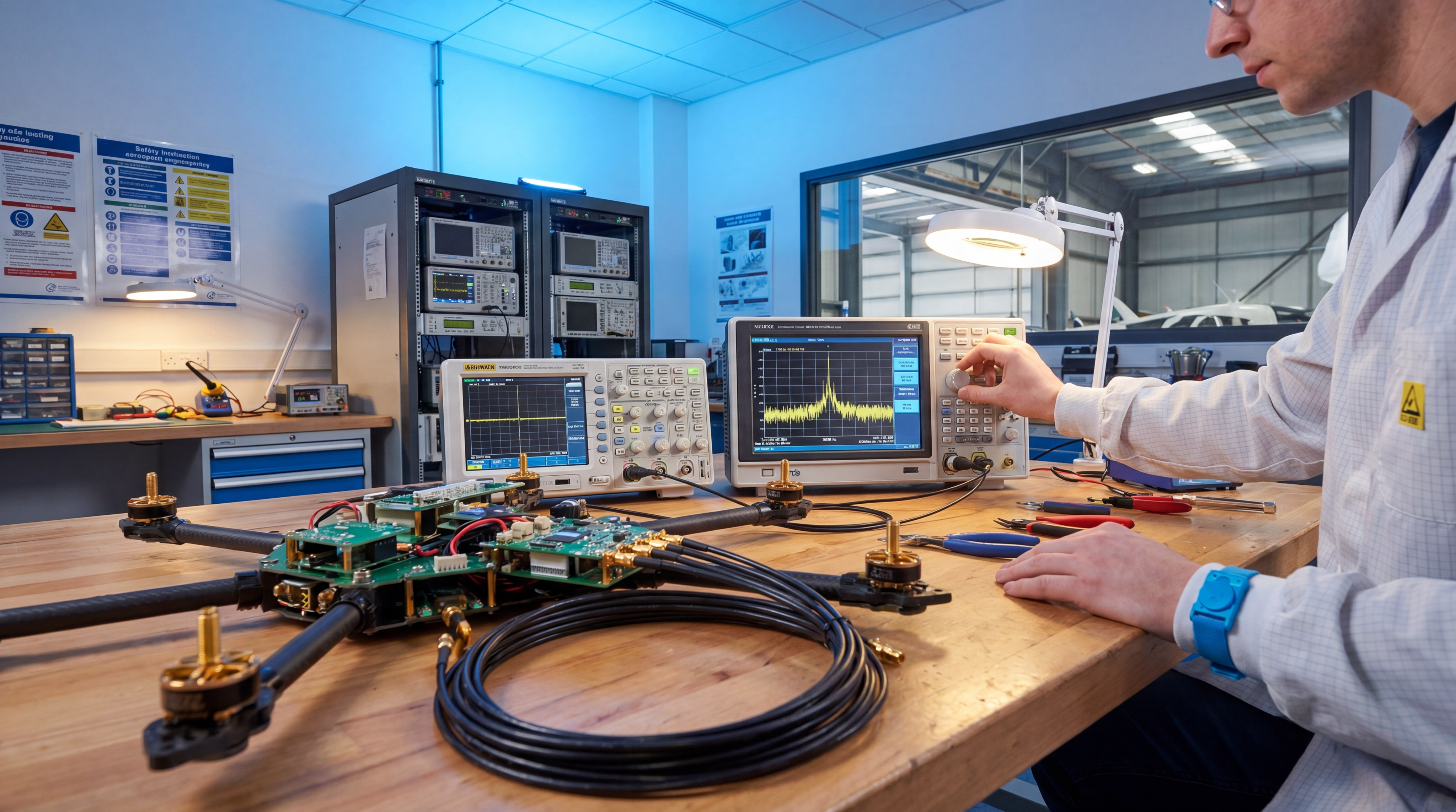
You must fine-tune this balance during laboratory testing before deploying your system in the field. This engineering discipline ensures consistent communication performance during actual missions.
What is the role of automatic gain control loops?
Automatic gain control loops dynamically adjust the gain of your system to maintain a stable output voltage under varying channel conditions. This keeps your communication link alive during rapid altitude changes and deep fades.
Here is the real catch:
- Feedback loops monitor RSSI and apply instant attenuation during power surges.
- Fast attack times protect your system from high-intensity radar sweeps.
- Hysteresis bands prevent the controller from chattering on noisy signal edges.
Key Takeaway: Optimizing dynamic range through active-passive staging ensures your UAV can process varying signal levels without losing telemetry lock.
| Control Element | Parameter Adjusted | Impact on Dynamic Range | Primary Benefit |
|---|---|---|---|
| LNA Bias Control | Transconductance / Gain | Shifts the upper compression point | Prevents intermodulation distortion |
| VVA Network | Continuous Attenuation | Levels incoming carrier power | Avoids analog-to-digital clipping |
The summary table above demonstrates how adjusting active and passive parameters dynamically stabilizes your signal window under volatile conditions.
What design challenges affect high-frequency UAVs?
High-frequency UAV systems must overcome extreme atmospheric absorption and micro-scale board parasitics to maintain their high-bandwidth data links. Operating in Ku, Ka, or millimeter-wave bands requires exceptionally precise signal path management. Specifying high-frequency Amplifiers and Attenuators allows you to manage these short, high-energy wave cycles. At these gigahertz frequencies, even a tiny layout mismatch can ruin your return loss.
How does atmospheric absorption affect Ka-band links?
Atmospheric absorption affects Ka-band links by causing severe signal attenuation due to water vapor and oxygen molecular resonance. This effect becomes especially pronounced during rainy weather or in high-humidity zones.
But wait, there is more:
- Water molecules absorb microwave energy and convert it to heat.
- Signal attenuation spikes dramatically at specific frequencies like 60 GHz.
- Rain fade requires you to maintain a much higher link margin than normal.
You can combat this environmental loss by designing an active uplink power control loop. This system boosts output power dynamically to punch through thick cloud cover.
Can you minimize board-level parasitic capacitance?
You can minimize board-level parasitic capacitance by utilizing low-loss PTFE substrates and optimized coplanar waveguide layouts. At high frequencies, standard FR-4 circuit boards absorb your signal and distort wave impedance.
Here is the absolute reality:
- Parasitic stubs on component pads create unexpected signal reflections.
- Blind vias remove capacitive stubs that act as tiny RF resonators.
- Proper guard trace isolation stops high-frequency board crosstalk cold.
Key Takeaway: Designing for high-frequency bands requires you to account for atmospheric fade and PCB parasitics using specialized, low-loss RF hardware.
| Frequency Band | Key Physical Challenge | Primary Hardware Solution | Operational Trade-off |
|---|---|---|---|
| Ku-Band (12-18 GHz) | Moderate rain fade susceptibility | High-efficiency GaN power blocks | Moderate thermal dissipation load |
| Ka-Band (26-40 GHz) | High atmospheric absorption | Precision waveguiding and LNAs | High manufacturing tolerance cost |
The reference matrix above highlights how moving up the spectrum alters your design choices, showing why high-frequency links require specialized engineering.
How can thermal dissipation issues be mitigated?
Thermal dissipation issues can be mitigated by combining high-efficiency semiconductor materials with thermally conductive structural enclosures. High-power transmitters generate significant waste heat within enclosed drone payload bays. Choosing thermally rugged Amplifiers and Attenuators is essential to prevent thermal runaway in flight. Failing to manage this heat will cause your RF components to degrade in power output and fail prematurely.
Why do GaN amplifiers generate intense local heat?
GaN amplifiers generate intense local heat because they operate at very high power densities within micro-scale semiconductor channels. While GaN offers incredible power-added efficiency, the remaining waste energy turns into intense heat.
Think about it:
- High power density raises junction temperatures rapidly if uncooled.
- Elevated junction heat degrades the amplifier’s output power and efficiency.
- Thermal stress shortens the mean time between failures of your electronics.
You must path this heat away from the chip carrier immediately. This active heat transfer keeps your components running cool and performing at their peak.
What are the best materials for UAV heat sinks?
The best materials for UAV heat sinks are lightweight metals like copper-doped aluminum or advanced anisotropic pyrolytic graphite. These materials offer exceptional thermal conductivity without adding excess weight to your payload.
Here is the real catch:
- Copper spreaders pull heat away quickly but impose a heavy weight penalty.
- Aluminum 6061 heat sinks provide the best balance of weight and thermal transfer.
- Pyrolytic graphite spreaders route heat sideways along ultra-thin profiles.
Key Takeaway: Mitigating thermal stress in your RF front-end preserves component life and prevents power droops during critical phases of flight.
| Material | Thermal Conductivity (W/m·K) | Density (g/cm³) | Structural Role in UAVs |
|---|---|---|---|
| Aluminum 6061-T6 | 167 | 2.70 | Standard chassis and heat sink fins |
| Pyrolytic Graphite | 1700 (in-plane) | 2.20 | Thin thermal spreaders for tight spots |
The comparative table above outlines the physical properties of top thermal management materials, guiding you to optimize your payload’s weight-to-cooling ratio.
Why is VSWR matching critical for link integrity?
Voltage Standing Wave Ratio matching is critical for link integrity because it prevents signal reflections from degrading transmission power and damaging your transmitter. Imbalanced impedance across your transmission lines causes forward power to bounce back toward your source. Integrating matching networks alongside Amplifiers and Attenuators stabilizes the overall load impedance. This layout control protects your active stages from destructive standing wave voltages.
How do impedance mismatches cause power loss?
Impedance mismatches cause power loss by creating reflected waves that interfere with your forward-traveling communication signal. This mismatch occurs when the characteristic impedance of your coaxial cable differs from your antenna.
Here is the absolute reality:
- Reflected waves subtract directly from the transmitted power, reducing EIRP.
- High reflected power triggers automatic transmitter safety back-offs.
- Severe mismatches create high-voltage hot spots along your transmission line.
You can calculate these losses easily using Smith Chart matching techniques. Correcting these errors ensures all your battery power is converted into broadcast energy.
Can passive pads improve your overall VSWR?
Passive pads can improve your overall VSWR by absorbing reflected signal power before it can reach your active transmitter output. Inserting a tiny inline attenuator reduces the return loss of mismatched components.
Let’s look closer:
- A 3 dB attenuation pad provides 6 dB of return loss improvement.
- Reflected signals travel through the pad twice, suffering double the loss.
- This isolation technique protects sensitive outputs from fluctuating antenna loads.
Key Takeaway: Maintaining a low VSWR across your RF transmission path protects your electronics from damage and maximizes your broadcast efficiency.
| Target VSWR | Return Loss (dB) | Reflected Power (%) | System Health Status |
|---|---|---|---|
| 1.15 : 1 | 23.1 | 0.5% | Excellent match; no risk of damage |
| 1.50 : 1 | 14.0 | 4.0% | Acceptable for tactical flight |
The standing-wave reference chart above illustrates how matching precision directly impacts power efficiency, showing why checking your reflections is vital.

How do you select the right hardware footprint?
You select the right hardware footprint by evaluating the tight size, weight, and power (SWaP) constraints of your unmanned aircraft. Small tactical drones require surface-mount components, while large military platforms can accommodate heavy connectorized modules. Balancing these packaging styles with your Amplifiers and Attenuators dictates your final airframe payload limit. Choosing the wrong format can reduce your flight time or compromise structural layout.
What are the benefits of surface-mount components?
Surface-mount components provide the lowest possible weight and size for highly integrated drone flight controllers. By soldering components directly onto a single multi-layer PCB, you eliminate heavy interconnect cables.
But wait, there is more:
- SMD components weigh fractionally less than connectorized metal housings.
- Short lead traces minimize parasitic inductance and capacitive coupling.
- Automated assembly reduces manufacturing costs for high-volume drone lines.
You must design a robust ground plane under surface-mount devices to handle heat. Proper layout prevents thermal issues from degrading your small-scale electronics.
When are connectorized modules necessary?
Connectorized modules are necessary when your system requires high levels of electromagnetic shielding or simple field-replacement capabilities. These rugged metal boxes shield internal circuits from powerful onboard motor interference.
Think about it:
- Metal enclosures offer complete isolation from nearby payload electronics.
- Standard coaxial interfaces make swapping modules in the field effortless.
- Connectorized parts can handle higher power levels and extreme vibrations.
Key Takeaway: Selecting component packaging that matches your drone’s payload constraints ensures both hardware reliability and maximum flight endurance.
| Packaging Format | Typical Unit Weight | Primary Aerospace Advantage | Field Serviceability |
|---|---|---|---|
| Surface-Mount (SMT) | $< 2$ grams | Minimal weight and parasitic loss | Requires specialist lab rework |
| Connectorized Module | $30 – 150$ grams | Rugged shielding and high power | Plug-and-play coaxial swap |
The trade-off matrix above highlights how your packaging choice impacts flight metrics, helping you pick the ideal layout for your drone.
What does the future hold for UAV link design?
The future of UAV link design lies in smart, adaptive cognitive radio front-ends that dynamically adjust their frequency and power levels in real time. Next-generation platforms will integrate software-defined control directly into the physical layer components. This transition relies on flexible Amplifiers and Attenuators that can respond immediately to software commands. By adapting to spectrum congestion on the fly, future drones will maintain solid links in hostile zones.
How will cognitive radio front-ends operate?
Cognitive radio front-ends will operate by using onboard artificial intelligence to continuously scan the surrounding electromagnetic environment. When the system detects localized jamming or heavy traffic, it instantly hops frequencies.
Let’s get right to the point:
- Machine-learning algorithms predict signal degradation before it disconnects.
- On-the-fly filtering blocks high-power localized interference sources.
- Adaptive gain adjustments keep the signal within the linear demodulation window.
This active defense mechanism is becoming standard for tactical defense and long-range logistics missions. You gain a major operational edge over static systems.
Will phased-array antennas become standard?
Will phased-array antennas become standard on drones because they allow you to steer your communication beam electronically without moving parts? Yes, this spatial targeting maximizes transmission power toward the ground station while ignoring noise from other directions.
Think about it:
- Electronic beam steering maintains tracking during radical flight maneuvers.
- Highly focused directional beams increase your operational range dramatically.
- Spatial nulling actively rejects anti-aircraft jamming signals.
Key Takeaway: Embracing adaptive antennas and smart gain controllers prepares your drone platforms for the crowded and congested airwaves of tomorrow.
| Next-Gen Technology | Operational Benefit | Primary Hardware Requirement | Horizon Date |
|---|---|---|---|
| Cognitive RF Frontend | Intelligent jammer avoidance | Fast-switching attenuators and gain blocks | Active Deployment |
| Active Phased Arrays | Solid beam-steering tracking | Integrated multi-channel amplifier dies | Future Standard |
The development timeline above tracks upcoming shifts in communication architectures, showing how active and passive components continue to evolve.
Establishing a reliable, optimized UAV communications front-end requires overcoming path loss, signal saturation, heat dissipation, and tight aerospace physical spaces. Corelix RF designs and manufactures factory-direct, high-performance solid-state power amplifiers and microwave front-ends that empower drone builders to achieve extreme range and mission success. By providing rugged, in-house engineered solutions spanning 30 MHz to 110 GHz, we turn complex RF design limitations into operational security and tactical advantage. To resolve your specific range, power, and thermal challenges, contact us today to schedule an engineering consultation and receive an active-passive payload evaluation roadmap.
Frequently Asked Questions
Can I solve all my range issues by simply installing a larger transmitter amplifier?
No, installing a larger amplifier is not a viable strategy for resolving range issues. Doing so will dramatically increase your weight, battery draw, and heat generation while risking severe receiver saturation and regulatory violations.
What’s the best way to determine if my drone’s receiver is experiencing signal overload?
The best way to identify receiver overload is by monitoring your system’s bit error rate and packet loss metrics during close-range testing. If you see telemetry drop out or clip when the drone is near the ground transmitter, your receiver is getting saturated and needs attenuation.
Can I use a passive attenuator to improve my transmitter’s VSWR match?
Yes, placing a passive attenuator pad is a highly effective way to stabilize your system’s VSWR. The attenuator absorbs reflected power twice—once as it goes to the mismatch and once as it returns—which significantly reduces the returned stress on your transmitter.
How do I know if my high-altitude drone needs hermetically sealed components?
You definitely need hermetically sealed components if your missions climb above ten thousand feet. Rapid atmospheric pressure drops and extreme cold-to-warm temperature swings cause moisture condensation that can short out open-air microstrip lines.
What’s the best component layout for a weight-constrained micro-drone system?
The best layout is a highly integrated surface-mount layout directly on a low-loss PCB. This completely bypasses the massive weight penalty and cable loss associated with heavy connectorized metal boxes and manual coaxial connections.