Utilizing a curated suite of RF/microwave test equipment—such as spectrum analyzers, near-field probes, LISNs, antennas, attenuators, and low-noise amplifiers—is the ultimate way to execute successful in-house EMC precompliance testing. Discovering that your new product has failed its official electromagnetic compatibility run is an absolute nightmare for any engineering team. You face thousands of dollars in re-testing fees, months of project delays, and the immense pressure of scrambling to redesign board layouts without real-time diagnostic visibility.
This blind troubleshooting not only drains your team’s energy but also risks missing critical market windows, leaving your competitors with an open field. Fortunately, establishing an in-house EMC precompliance bench allows you to identify, locate, and mitigate electromagnetic interference (EMI) issues early in the design cycle, transforming a high-risk lab certification into a predictable, first-pass success.
What Is EMC Precompliance Testing?
Implementing a structured EMC precompliance testing program is the single most effective way to identify and mitigate electromagnetic interference issues before committing to formal laboratory certification. By gathering early spectral emissions data on your own workbench, you bypass the typical “guess-and-check” cycle.
This proactive diagnostics approach lets you spot design flaws when they are easiest and cheapest to fix. You can systematically test your product under realistic operating conditions without paying high-dollar laboratory rates.
The High Cost of Certification Failures
Think about it. Every time your product fails an official lab chamber run, your budget takes a massive hit. Lab time easily costs thousands of dollars per day, not to mention the weeks of scheduling delays that push back your product launch.
You can protect your financial resources by catching these issues early on your own workbench. Consider these typical real-world failure consequences:
- Lab booking fees and transportation costs accumulate rapidly.
- Re-engineering printed circuit boards adds hardware iteration costs.
- Missed time-to-market windows can hurt your brand’s competitive advantage.
How Precompliance Saves Time and Capital
Here is the deal: spending a fraction of your certification budget on a basic precompliance setup pays for itself almost immediately. You can run unlimited, risk-free scans right at your desk to verify your layout modifications.
You will achieve significant schedule savings while empowering your development team. Review these immediate precompliance benefits:
- Rapid iteration cycles occur in hours rather than weeks.
- Development schedules remain highly predictable and on track.
- Engineers build deep in-house expertise in EMI mitigation.
What Are the Essential Setup Requirements?
Setting up a reliable diagnostics area does not require building an expensive semi-anechoic chamber. You simply need a quiet corner of your lab, a clean metal ground plane, and basic ambient-noise mitigation tools.
You can establish an effective diagnostic bench without a massive capital investment. Consider these physical bench requirements:
- A solid copper or aluminum ground reference plane is essential.
- Inexpensive RF absorbing materials help isolate nearby wireless signals.
- Consistent equipment spacing ensures repeatable testing geometry.
Now, let’s look at the absolute bottom line of early testing.
Key Takeaway: Early-stage precompliance testing acts as an insurance policy for your official regulatory runs, transforming high-risk lab certifications into predictable, first-pass successes.
| Precompliance Element | Primary Objective | Key Physical Asset |
|---|---|---|
| Conducted Emission Testing | Measure noise traveling back to power grid | Ground plane & LISN |
| Radiated Emission Diagnostics | Detect airborne electromagnetic fields | Spectrum analyzer & Antennas |
| Ambient Noise Baseline | Isolate external signals from EUT emissions | Shielded enclosures or tent |
This structural breakdown helps you organize your workspace effectively before introducing active test instruments.
Why Is a Spectrum Analyzer Essential?
A high-performance spectrum analyzer serves as the primary visual window into your device’s RF emissions, making it the most critical instrument on any EMC precompliance workbench. This indispensable tool captures electrical signals in the frequency domain, allowing you to easily identify harmonic peaks that violate regulatory limits.
Visualizing the Frequency Spectrum
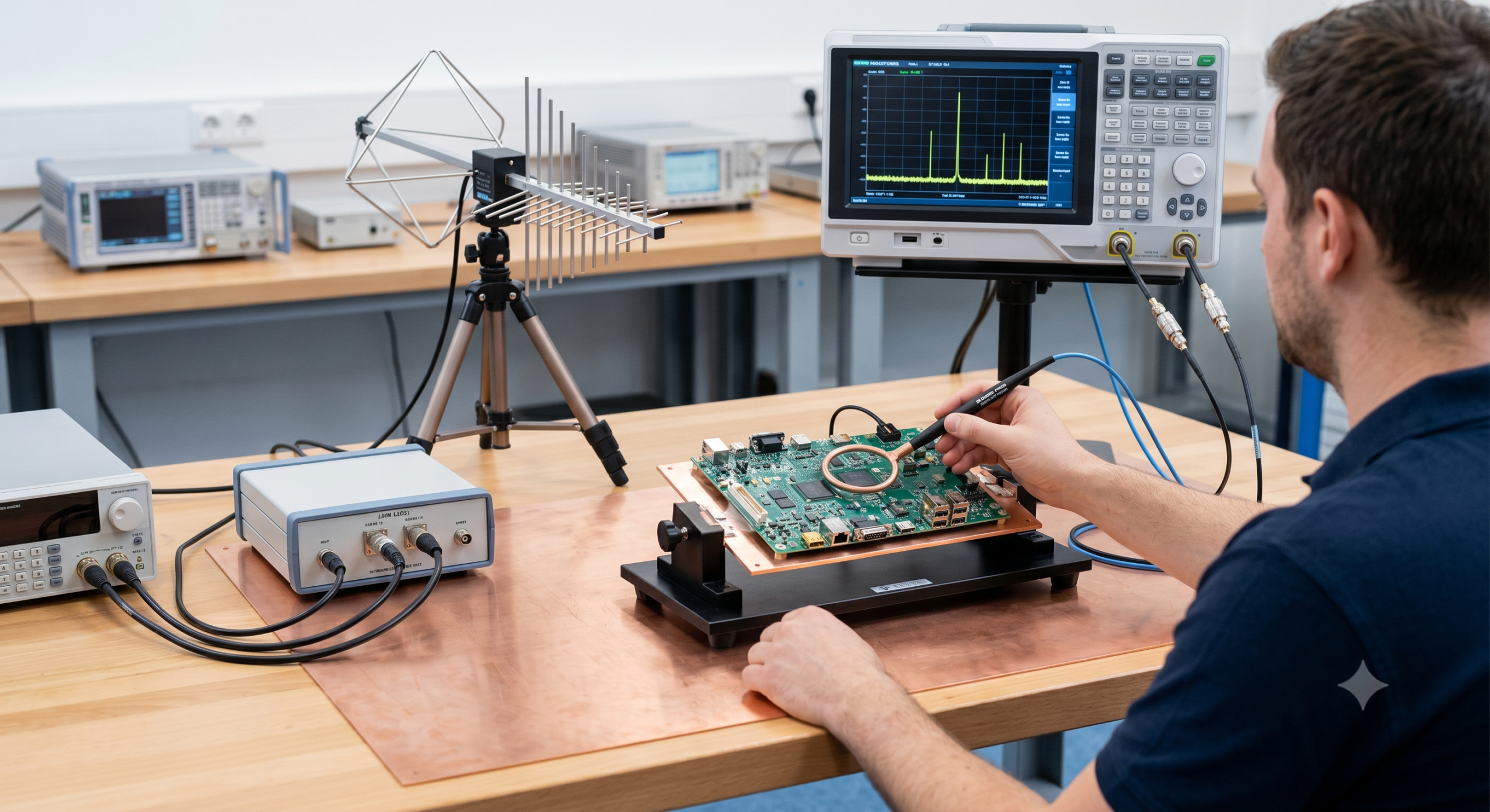
How does this work? The spectrum analyzer displays signal amplitude against frequency, immediately revealing the exact frequencies where your device is radiating energy. As you can see in Figure 1, a modern digital spectrum analyzer displaying a frequency sweep with distinct peak emission spikes in a laboratory environment is vital for tracking down stray spikes: 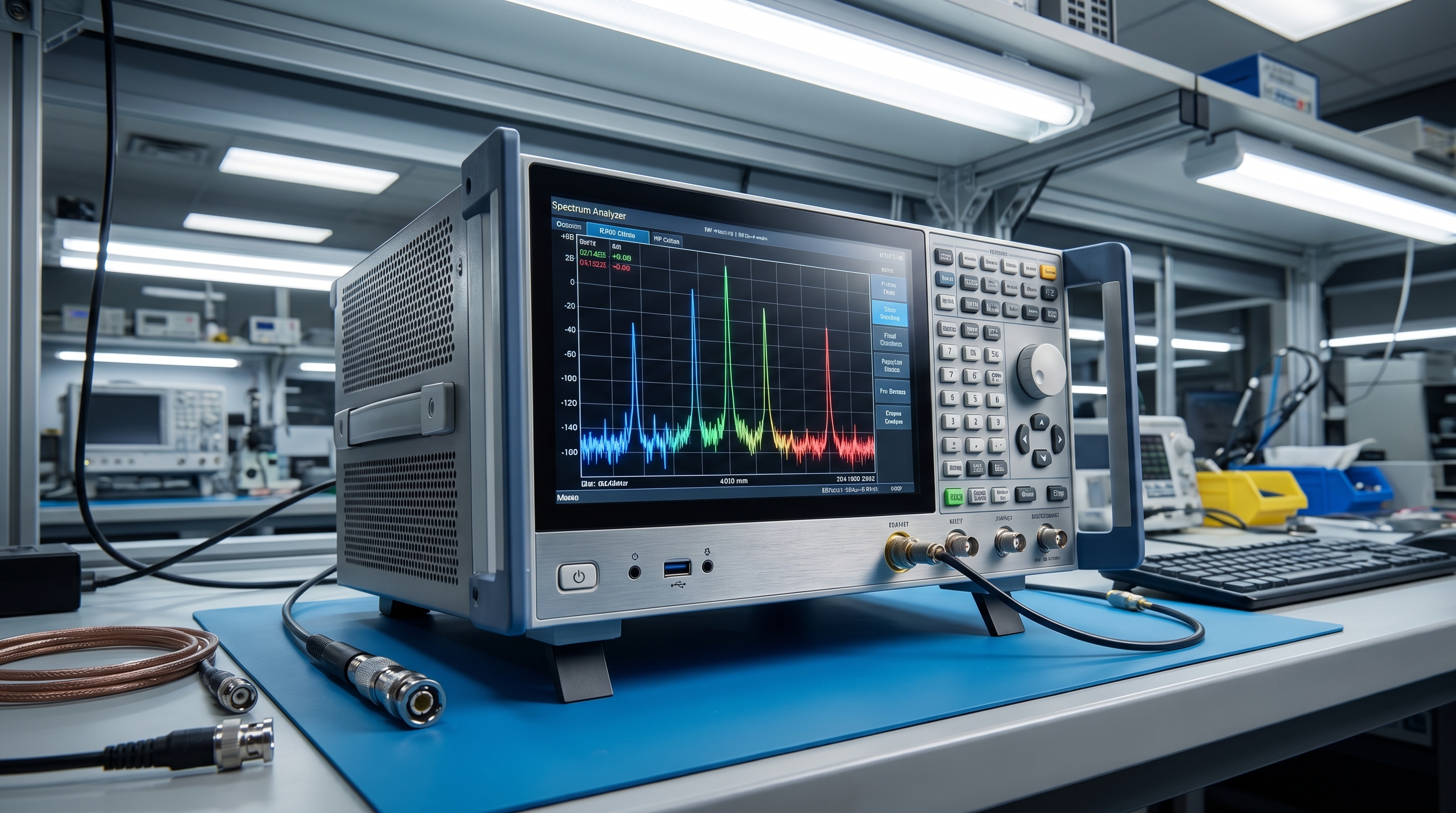
This visualization helps you immediately isolate problems on your screen. Keep an eye out for these specific spectral features:
- Harmonic spikes point directly to clock frequencies or switching regulators.
- Broadband noise floors reveal poor ground designs or shielding gaps.
- Real-time spectral analysis helps you catch intermittent transient signals.
Peak vs. Quasi-Peak Detection Modes
Let’s break it down: peak detection finds the absolute worst-case emissions in seconds, whereas quasi-peak detection weighs those signals based on their duration. You should use peak detection for rapid debugging to save valuable hours.
You can switch between these modes to balance speed and accuracy. Focus on these detector properties:
- Peak detection provides instantaneous, worst-case envelopes.
- Quasi-peak detection matches the receiver response of official test compliance.
- Average detection is used to evaluate continuous, narrowband emissions.
Choosing the Right Bandwidth Settings
To obtain meaningful diagnostic data, you must configure the Resolution Bandwidth (RBW) to align with standard CISPR and FCC regulations. Mismatched RBW settings will result in either overestimating or underestimating your emission levels.
You need to match these settings to the correct target frequencies. Follow these regulatory guidelines:
- Use a 9 kHz RBW for conducted emissions testing (150 kHz to 30 MHz).
- Use a 120 kHz RBW for radiated emissions testing (30 MHz to 1 GHz).
- Use a 1 MHz RBW for high-frequency microwave testing (above 1 GHz).
Matching these specific parameters ensures your bench measurements closely mirror formal lab conditions.
Key Takeaway: Configuring correct detector types (peak vs. quasi-peak) and matching resolution bandwidths to regulatory standards is vital to preventing false passes during in-house diagnostics.
| Spectrum Analyzer Feature | Ideal Precompliance Setting | Regulatory Standard Match (CISPR) |
|---|---|---|
| Frequency Range | 9 kHz to 3 GHz (minimum) | Bands A through D |
| Resolution Bandwidth (RBW) | 9 kHz (conducted), 120 kHz (radiated) | CISPR 16-1-1 compliant |
| Detector Modes | Peak (fast scanning), Quasi-Peak (verification) | Quasi-Peak & Average |
Once the spectrum analyzer is configured to view emissions, specialized antennas must be deployed to capture radiated signals accurately from the surrounding environment.
How Do Antennas Capture Radiated Emissions?
Capturing radiated electromagnetic energy for EMC diagnostics requires specialized broadband antennas designed to perform reliably across broad frequency spectrums. These antennas act as the transducer that converts airborne electric and magnetic field energy into a guided wave that your spectrum analyzer can read.
Biconical vs. Log-Periodic Antennas
But wait, there’s more. You cannot rely on a single antenna type to cover the entire compliance spectrum because different designs excel at different frequency bands.
You must choose your antennas based on your target standards. Consider these core antenna types:
- Biconical antennas are ideal for the lower 30 MHz to 300 MHz band.
- Log-periodic antennas offer directional gain from 300 MHz to several GHz.
- Combined “Bilog” antennas offer a convenient, wideband single-antenna solution.
Understanding Antenna Factors
Here’s the deal: raw voltage readings on your spectrum analyzer do not equal absolute field strength. You must apply the manufacturer’s calibrated Antenna Factor (AF) to convert dBµV to dBµV/m.
You need to combine multiple factors to get an accurate representation of the field. Note these key parameters:
- Antenna Factor compensates for the antenna’s frequency-dependent loss and gain.
- Cable loss must also be added to the calculation for true accuracy.
- Modern spectrum analyzers let you load these correction curves automatically.
How to Maintain Proper Calibration?
You must treat your precompliance antennas with extreme care to prevent physical damage from throwing off your calibration curves. Simple actions like dropping an antenna or altering its element spacing can ruin your measurement accuracy.
You should follow routine preservation practices to maintain test consistency. Use these maintenance steps:
- Perform regular visual inspections for corrosion or loose connections.
- Maintain consistent polarization (horizontal vs. vertical) relative to your EUT.
- Store antennas in padded cases to prevent bending the sensitive elements.
Understanding these key antenna principles is the first step toward obtaining reliable radiated measurements.
Key Takeaway: Selecting the correct antenna for your target frequency band and accurately applying its specific Antenna Factors is critical to obtaining measurements that correspond to official test chamber data.
| Antenna Type | Operating Frequency Range | Key Precompliance Role |
|---|---|---|
| Biconical Antenna | 30 MHz to 300 MHz | Low-frequency radiated emission profiling |
| Log-Periodic Dipole Array | 200 MHz to 2 GHz+ | High-frequency, directional EMI localization |
| Monopole Active Rod | 9 kHz to 30 MHz | Low-frequency magnetic/electric field testing |
While broadband antennas capture far-field radiated energy, pinpointing the exact components responsible for those emissions requires localized diagnostic tools.
Why Use Near-Field Probes for Debugging?
Near-field probes are indispensable EMC diagnostics tools that allow engineers to move beyond generalized far-field observations and isolate exact electromagnetic leakage points on a physical circuit board. By sniffing close to traces, connectors, and IC pins, you can easily identify exactly which components are acting as unintentional radiators.
E-Field vs. H-Field Probes Explained
Let’s break it down: electric field (E-field) and magnetic field (H-field) probes detect entirely different emission sources on your board. As shown in Figure 2, an engineer holding an H-field near-field probe over a complex printed circuit board with glowing traces under a workbench lamp helps pinpoint localized emission hotspots: 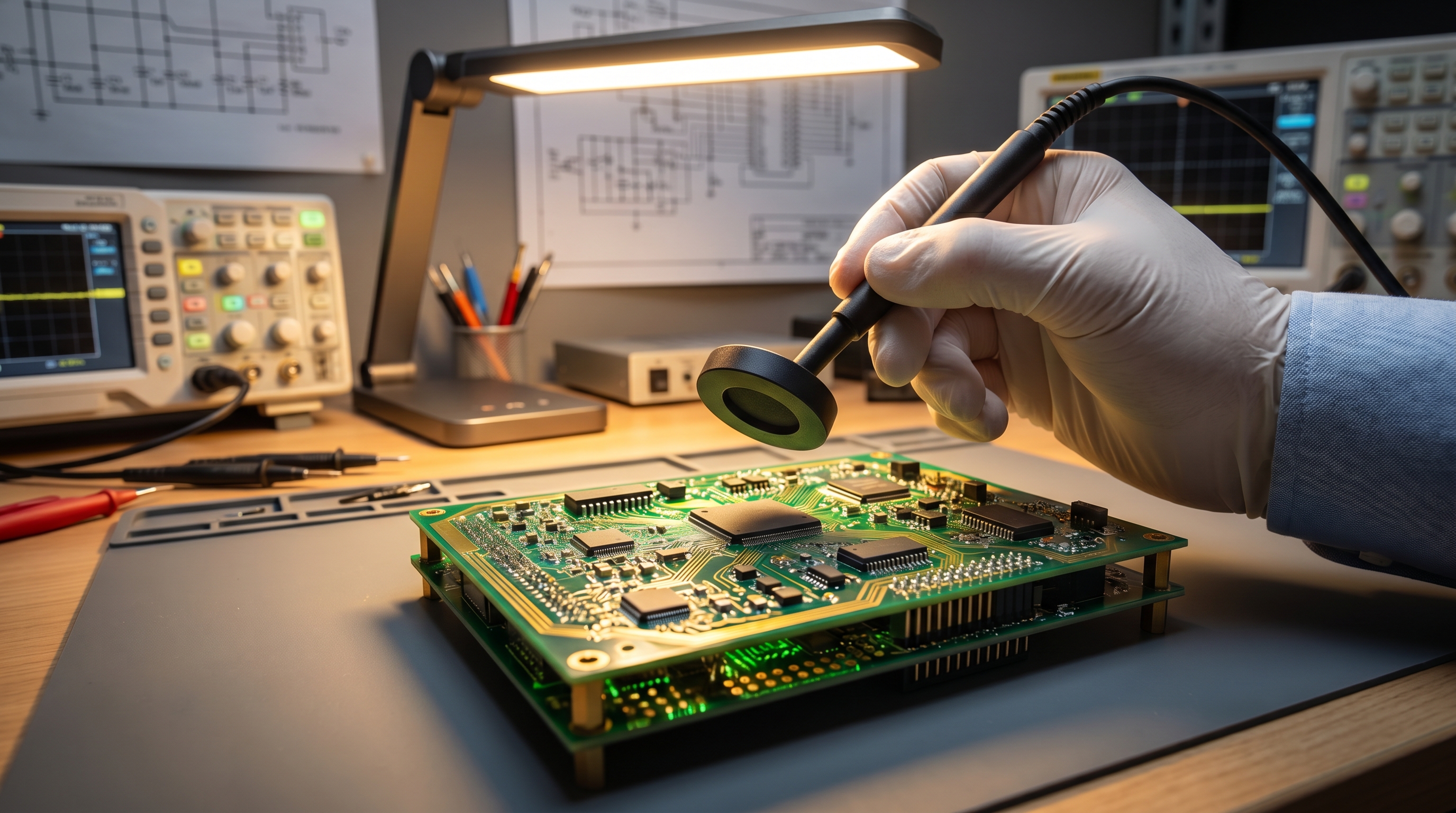
Choosing the right size of magnetic loop or electric stub helps you find noise sources on your board. Check these primary differences:
- H-field probes are highly sensitive to high-current loops and switching regulators.
- E-field probes excel at detecting high-voltage nodes, open traces, and shield seams.
- Smaller probe tips offer better spatial resolution but lower overall signal sensitivity.
Pinpoint Emissions at the Component Level
Think about it. When an antenna tells you that your product is failing at 400 MHz, you still do not know which chip is the culprit. By sweeping a near-field probe across your board, you can trace the exact copper trace carrying that noise.
You can methodically pinpoint the sources of radiation on your circuit board. Focus on these scanning techniques:
- Scan power supply switch nodes, high-speed clocks, and ribbon cables.
- Test metal enclosures at the seams and joints to check for leakage.
- Apply quick fixes like shielding tape to see immediate reduction on screen.
Mastering board-level probing saves weeks of blind troubleshooting and costly redesigns.
Key Takeaway: Near-field probes do not provide absolute regulatory pass/fail numbers, but their ability to localize emission hotspots makes them the ultimate board-level debugging tool.
| Probe Type | Primary Sensitivity | Common Debugging Target |
|---|---|---|
| H-Field (Magnetic) | Current-carrying loops | Switching regulators, PCB traces, decoupling caps |
| E-Field (Electric) | High-impedance voltage nodes | High-speed clock lines, trace stubs, chassis joints |
| Sniffer/Stub Probe | Ultra-localized fields | Single pin diagnostics, microscopic trace runs |
After resolving radiated emissions at the board level, engineers must pivot to addressing interference that travels directly down the power lines.
What Is the Role of a LISN in EMC?
A Line Impedance Stabilization Network (LISN) is a fundamental device used to measure conducted EMC emissions on power cords while isolating the equipment under test from external mains noise. This hardware interface blocks power grid interference so that you are only measuring the noise generated by your own device.
Isolating the Power Source Impedance
How does this work? The LISN provides a stable, standardized RF impedance (usually 50 ohms) across the power lines to ensure consistent testing. As illustrated in Figure 3, a Line Impedance Stabilization Network device in a laboratory setup with clean cabling and grounding plates ensures clean, repeatable test conditions:
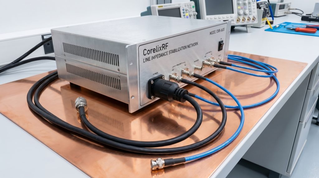
This physical baseline ensures your measurement setup remains consistent across different test locations. Check these key functions:
- Standardized impedance prevents local mains variance from skewing your data.
- High-frequency grid noise is shunted directly to the ground plane.
- A clean power baseline is established for both AC and DC systems.
Measuring Conducted Emissions Safely
But wait, there’s more. Mains power lines carry lethal voltages and high-energy transient spikes that can easily blow out your spectrum analyzer’s input stage. You must implement robust transient protection and follow strict safety grounding protocols.
You can ensure safe operation on your test bench. Keep these safety practices in mind:
- Always use a heavy-duty copper ground connection to prevent electric shock.
- Install a high-quality transient limiter to protect your analyzer’s RF mixer.
- Check both the line and neutral paths to catch all conducted noise sources.
Taking these safety precautions is vital for protecting both yourself and your valuable test instruments.
Key Takeaway: A LISN is essential for conducted emissions testing because it standardizes mains impedance, blocks grid noise, and routes the EUT’s RF emissions safely to your spectrum analyzer.
| LISN Metric | AC Power Configurations | DC Power Configurations |
|---|---|---|
| Standard Impedance | 50 µH // 50 Ohms | 5 µH // 50 Ohms (or 50 µH) |
| Primary Frequency Range | 150 kHz to 30 MHz | 100 kHz to 100 MHz (automotive) |
| Safety Equipment | Transient limiter + 10 dB attenuator | 10 dB attenuator |
Managing conducted and radiated emissions covers the emissions aspect of EMC, but precompliance must also account for a device’s susceptibility to incoming interference.
When Are RF Signal Generators Required?
Conducting robust electromagnetic immunity testing requires a reliable RF signal generator to simulate real-world radio frequency threats and evaluate how your system behaves under environmental EMC stress. Rather than just measuring what your device emits, you must inject controlled RF signals to see if your electronics will malfunction in the field.
Testing for RF Electromagnetic Immunity
Here is the deal: products operating near cell towers, industrial machinery, or walkie-talkies are constantly bombarded with RF fields. You need to verify that these fields will not cause your processor to reset or corrupt your sensor readings.
You can set up a low-cost immunity baseline to check system susceptibility. Look at these testing steps:
- Inject modulated RF energy into power and signal cables.
- Radiate small-scale enclosures using a near-field transmission loop.
- Identify specific failure thresholds across critical frequencies.
Generating Continuous Wave & Modulated Signals
Think about it. Real-world interference is rarely a clean, unmodulated carrier wave. You must apply standard modulation profiles to test your system’s resilience against complex modern communication signals.
You can match typical field conditions by using the right modulations. Focus on these standard profiles:
- Use Amplitude Modulation (AM) to simulate analog broadcasting bands.
- Use Pulse Modulation (PM) to test immunity against mobile phones and radar.
- Adjust the sweep rate and step size to systematically probe for weak spots.
This thorough stress-testing ensures your device can withstand harsh electromagnetic environments.
Key Takeaway: A versatile RF signal generator is key to evaluating system immunity, helping you find and patch device susceptibility paths before formal compliance testing.
| Signal Type | Common Test Target | Modulation Scheme |
|---|---|---|
| Continuous Wave (CW) | Standard RF calibration | Unmodulated carrier |
| Amplitude Modulation (AM) | Commercial immunity (IEC 61000-4-3/6) | 1 kHz sine, 80% depth |
| Pulse Modulation (PM) | Radar & mobile phone simulation | Gated pulse sequences |
Because high-power signals from signal generators and power amplifiers can feed directly back into your diagnostic gear, implementing robust signal protection is paramount.
How Do RF Attenuators Protect Equipment?
Safeguarding expensive test instruments from high-energy spikes and overload during destructive EMC testing requires the strategic integration of reliable coaxial inline attenuators. These robust components absorb harmful, high-power transients and match impedances to prevent signal reflections from skewing your traces.
Preventing Input Stage Overload
Let’s break it down: a high-power spike from a LISN or immunity amplifier can instantly destroy the delicate input mixer of your spectrum analyzer. As shown in Figure 4, a high-detail close-up of high-power RF attenuators and low-loss cables on an engineering lab workbench demonstrates how precise impedance matching prevents signal reflections: 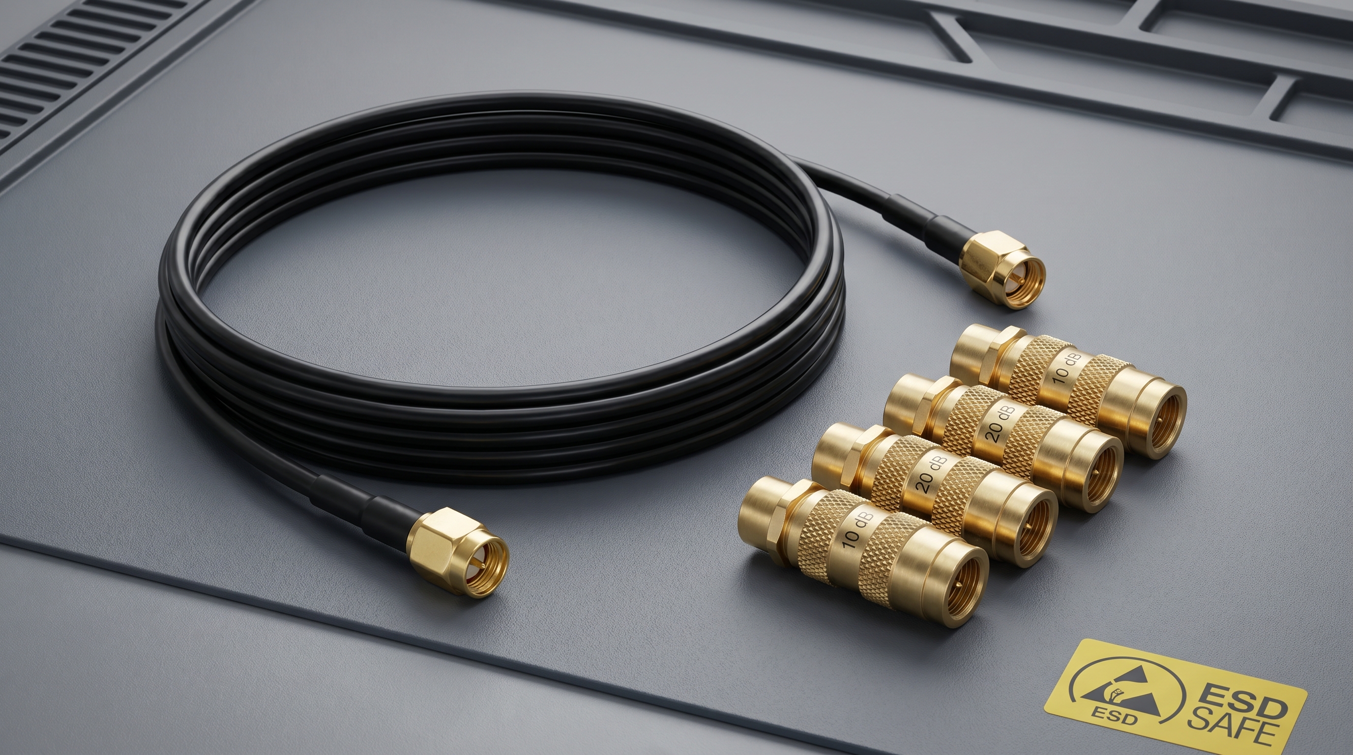
You should always keep a high-quality coaxial attenuator connected to your analyzer’s input port. Notice these essential benefits:
- Inline attenuators scale down unsafe voltage surges to manageable levels.
- They improve the VSWR (Voltage Standing Wave Ratio) of your signal path.
- Thermal dissipation capacity is critical when handling high-power signal sources.
Selecting Fixed vs. Variable Attenuators
How does this work? You can choose between fixed attenuators for reliable, continuous protection and step variable attenuators for fine-tuning your test signal levels. Incorporating high-quality RF attenuators ensures you get flat frequency responses and precise impedance matching across your entire diagnostic spectrum.
You should choose your protection devices based on power ratings. Review these common choices:
- Fixed attenuators (like 10 dB or 20 dB pads) are ideal for primary protection.
- Step attenuators allow you to dynamically adjust the attenuation during sweeps.
- Choose attenuators rated for the maximum peak power of your test setup.
Selecting the correct attenuation properties is crucial for maintaining instrument health and data integrity.
Key Takeaway: Never connect a LISN or high-power amplifier output directly to a spectrum analyzer without an inline RF attenuator or transient limiter to absorb hazardous energy spikes.
| Attenuator Category | Common Attenuation Value | Power Rating Recommendations |
|---|---|---|
| Fixed Inline Attenuator | 3 dB, 6 dB, 10 dB, 20 dB | 2W to 50W (based on signal source) |
| Step Attenuator | 0 to 110 dB in 1 dB steps | Low power (under 2W) for diagnostic tuning |
| Transient Limiter | ~10 dB (with built-in gas tubes) | Specialized protection for LISN outputs |
Just as attenuators protect critical inputs, the coaxial cables carrying these signals must prevent leakage and signal loss from compromising your diagnostic data.
Why Do RF Cable Assemblies Impact Accuracy?
High-frequency EMC precompliance measurements are highly sensitive to the physical properties of the interconnections, making high-performance coaxial cable runs a non-negotiable requirement for repeatability. Cheap, poorly shielded cables can act as unintentional antennas, sucking in ambient noise and throwing off your testing baseline.
Minimizing Phase and Insertion Loss
Here’s the deal: every decibel of loss in your cables directly degrades your signal-to-noise ratio. You must use phase-stable, low-loss RF cable assemblies to ensure that your spectrum analyzer sees exactly what your probe or antenna captures.
You cannot afford to let cable attenuation skew your amplitude readings. Look for these cable features:
- Standard RG-58 cables exhibit unacceptable loss at microwave frequencies.
- Double-shielded or semi-rigid cables maintain excellent amplitude accuracy.
- Phase stability prevents calibration drift when cables are moved.
The Shielding Effectiveness of Quality Cables
Think about it. If external FM radio stations or Wi-Fi signals leak into your signal lines, you will spend hours chasing “ghost” emissions. You need high-performance shielding and precision coaxial connectors to keep your measurement environment perfectly isolated.
You can achieve superior isolation by using high-quality components. Focus on these shielding guidelines:
- Look for cables with double-braided silver copper shielding.
- Precision N-type and SMA connectors prevent high-frequency signal leakage.
- Regularly clean and inspect your connector interfaces for debris.
Investing in high-grade connections is the simplest way to boost your test repeatability.
Key Takeaway: Cheap or damaged coaxial cables act as antennas, picking up ambient noise and distorting signal amplitudes; investing in shielded, low-loss RF cables is crucial for reliable test data.
| Coaxial Cable Type | Shielding Structure | Insertion Loss Profile (at 3 GHz) | Shielding Effectiveness |
|---|---|---|---|
| Standard RG-58 | Single braid (copper) | High (~0.8 dB/ft) | Poor (< 40 dB) |
| Double-Shielded RG-223 | Double braid (silver/copper) | Moderate (~0.4 dB/ft) | Excellent (> 80 dB) |
| Semi-Rigid / Flex-Form | Solid / Foil + Braid | Ultra-Low (~0.15 dB/ft) | Outstanding (> 100 dB) |
When highly shielded paths are established, the next challenge is boosting faint, hard-to-detect signals above the instrumentation noise floor.
What Is the Purpose of RF Amplifiers?
Resolving weak EMI emission signals that sit near or below your spectrum analyzer’s internal noise floor requires integrating low-noise EMC preamplifiers. These amplifiers boost the weak signals captured by your probes or antennas so they can be clearly read on your display.
Boosting Weak Signals Above the Noise Floor
But wait, there’s more. Placing a low-noise amplifier (LNA) close to your receiving antenna dramatically improves your system’s overall sensitivity. This allows you to catch marginal out-of-spec harmonic peaks that would otherwise remain hidden.
You can find faint signals that are typically lost in the noise floor. Review these primary advantages:
- LNAs lower the effective Displayed Average Noise Level (DANL) of your setup.
- They compensate for the high insertion losses of long cable runs.
- They maintain high gain flatness across the entire targeted frequency band.
Do You Need Solid-State Broadband Power?
Let’s break it down: you must not confuse low-power preamplifiers used for emission testing with high-power amplifiers used for immunity testing. For immunity, you need robust, solid-state RF amplifiers that can drive high-field-strength antennas without distorting.
You should select the correct active hardware for your specific test requirements. Check these amplifier differences:
- Preamplifiers focus on low noise figure and sensitive signal retrieval.
- Power amplifiers focus on maximum linear power output and ruggedness.
- Mismatching these amplifier types can lead to blown inputs or poor measurements.
Using the right amplifier for the job ensures your signals are always crystal clear.
Key Takeaway: A high-gain, low-noise preamplifier is indispensable for validating low-margin emission levels, ensuring you do not miss critical out-of-spec harmonic peaks.
| Amplifier Category | Typical Gain Profile | Noise Figure | Primary Precompliance Application |
|---|---|---|---|
| Low-Noise Preamplifier | 20 dB to 30 dB | < 3 dB | Boosting weak emissions from antennas/probes |
| Broadband Power Amplifier | 40 dB to 50 dB | N/A (high power) | Driving antennas for radiated immunity tests |
| Medium Power Driver | 10 dB to 20 dB | Standard | Signal source boost for cable injection |
Equipping your bench with these core diagnostic instruments lays the groundwork; understanding their deployment is best clarified through common industry questions.
What Are the Core EMC Testing FAQs?
Answering the most common EMC testing FAQs is essential for engineers trying to demystify complex measurement parameters, clear up technical confusion, and optimize their testing workflow. Let’s look at the most frequently asked questions to demystify complex testing concepts.
Can I Perform Full Certification in My Own Office?
No, you cannot perform legally binding EMC certification tests outside an accredited laboratory environment. Think about it. Your standard office workspace is flooded with ambient RF noise from Wi-Fi networks, cellular signals, and grid interference that completely masks your device’s true emissions.
Here is the deal: precompliance is built to locate and fix problems, not to provide certified passes.
- Standard offices lack the calibrated shielding of anechoic chambers.
- Ambient signals will create false failures on your spectrum analyzer trace.
- Certified laboratories use highly specific receiver configurations required by law.
What Is the Difference Between Near-Field and Far-Field?
Near-field measurements focus on magnetic and electric fields very close to your circuit board, while far-field measurements assess radiating electromagnetic waves propagated over several meters. Let’s break it down: near-field probing is your ultimate diagnostic tool for pinpointing noisy board-level components, but it cannot predict official far-field compliance directly.
You must understand how these two regions interact to optimize your mitigation strategy.
- Near-field measurements are dominated by localized reactive fields.
- Far-field measurements are dominated by propagating plane waves.
- Official limits are defined in the far-field (typically 3 or 10 meters).
Why Must I Use a Transient Limiter With My LISN?
Yes, you absolutely must use one because power line switching events generate massive, high-energy voltage surges that can instantly destroy your analyzer’s sensitive inputs. How does this work? When you turn your device on or off under test, the LISN generates massive transient voltage spikes that easily blow past standard input protection.
You can save thousands of dollars in instrument repairs by keeping a limiter inline.
- Transient limiters instantly clamp voltage spikes to safe levels.
- They introduce a minor insertion loss that you can easily calibrate out.
- Failing to use one risks immediate physical damage to your RF front-end.
Do Precompliance Antennas Need to Be Calibrated?
No, you do not need fully calibrated antennas for relative precompliance debugging, though calibration is essential if you want to calculate absolute field-strength values. But wait, there’s more. For daily diagnostic troubleshooting, your main goal is seeing if a design change reduces an emission peak rather than measuring its absolute legal margin.
You can comfortably verify layout improvements by comparing relative signal spikes.
- Uncalibrated antennas show peak frequency changes with perfect accuracy.
- Relative comparisons are highly effective for fast-paced prototyping phases.
- Calibrated antennas apply a specific Antenna Factor to yield absolute units.
What Is the Benefit of Quasi-Peak Over Peak Detection?
Quasi-peak detectors weigh signals based on their duration and repetition frequency to match official regulatory compliance, whereas peak detectors capture instantaneous worst-case maximums near-instantly. Think about it. You can save massive amounts of time by scanning your board quickly with a fast peak detector first, then using the slow quasi-peak detector only on your problematic frequency peaks.
You should integrate both detector modes strategically to keep your testing sessions efficient.
- Peak detection highlights maximum interference levels in seconds.
- Quasi-peak detection provides the official compliance weighting required for certifications.
- Combining both modes optimizes your bench scanning throughput.
Let’s summarize how these fundamental concepts impact your everyday precompliance strategy.
Key Takeaway: Understanding these core diagnostic FAQs and choosing the right sweep methods helps you design a highly efficient, reliable, and safe in-house testing routine.
| FAQ Concept | Key Takeaway | Technical Recommendation |
|---|---|---|
| In-Office Testing | Precompliance is diagnostic only | Use to identify relative improvements |
| Measurement Fields | Near-field is for debugging; far-field is for compliance | Use probes for board, antennas for room |
| Equipment Safety | Always protect analyzer inputs | Keep transient limiters and attenuators inline |
This structural review helps you clarify your overall diagnostic approach before finalizing your lab setups.
Conclusion
Successfully navigating regulatory requirements does not have to be an expensive, high-risk bottleneck in your product launch cycle. By integrating high-quality RF/microwave test equipment—including spectrum analyzers, near-field probes, LISNs, shielding, and premium coaxial interconnects—into your development workflow, you can identify, trace, and eliminate electromagnetic interference issues long before your product ever enters a formal test chamber. This proactive approach saves thousands of dollars in re-testing fees, prevents product delays, and optimizes engineering resources.
At Corelix RF, we are dedicated to providing engineers with high-performance, precision-engineered RF and microwave components that deliver repeatable, laboratory-grade accuracy. Whether you are building an in-house precompliance bench or upgrading your testing configurations, our comprehensive selection of attenuators, cable assemblies, and connectors is built to support your most demanding projects.
Are you ready to optimize your testing setup and ensure first-pass regulatory success? Please contact us today to find the perfect RF and microwave solutions for your precompliance testing needs.