
Authorized RF Review Boundary
Authorized Counter-UAS RF System Review Guide is maintained as a compliance-first engineering page. CorelixRF discusses regulated counter-UAS RF topics only for authorized programs with documented scope, lawful operating boundaries and buyer-side approval.
- RF front-end platform review for amplifier, antenna, source and control interfaces.
- Custom RF system review for enclosure, thermal, control and documentation needs.
- RFQ checklist for band, power, duty cycle, load, interface and acceptance inputs.
- Delivery documentation for inspection records, test curves and FAT-style evidence.
- Contact CorelixRF engineering sales with authorized project documents.
This page does not provide public deployment, evasion, interference, power-setting or bypass instructions. If a project cannot document legal authority, the correct next step is compliance review.
Primary Topic Hub and RFQ Path
This primary guide now consolidates related authorized C-UAS and RF safety review topics. Use it for lawful scope definition, RF interface review, documentation and factory RFQ preparation.
- How To Connect A Drone Jammer Module To Power? – consolidated reference
- How to Choose the Right Drone Jammer Module for Security? – consolidated reference
- How to Choose a Modular Anti-Drone Jammer Module for Security? – consolidated reference
- How to Choose the Right Drone Jammer for Facility Security? – consolidated reference
For regulated counter-UAS or interference-adjacent topics, CorelixRF keeps the discussion at authorized RF engineering review, documentation, test evidence and procurement boundaries. This page does not provide public deployment, evasion or unlawful interference instructions.
- RFQ checklist – prepare band, power, duty cycle, interface, cooling and acceptance inputs.
- RF configurator – turn project requirements into a first engineering brief.
- Delivery documentation – align test curves, inspection records and FAT-style evidence.
- Case studies – review how CorelixRF frames RF problems for buyer decisions.
- Contact engineering sales – submit the documented scope for review.
A drone jammer works by emitting powerful electromagnetic noise on the same radio frequencies used by a Unmanned Aerial Vehicle (UAV) to communicate with its operator or satellite network. Imagine a high-security facility where an unidentified drone suddenly appears, hovering over restricted zones and potentially capturing sensitive visual data. This intrusion agitates significant privacy concerns and poses a physical security risk to personnel and assets. To mitigate these threats effectively, understanding what is a drone jammer becomes essential, as this technology allows you to neutralize the aerial threat without resorting to destructive kinetic force.
What is a drone jammer and how does it function?
A drone jammer functions by broadcasting a “noise” signal that is stronger than the original command signal, effectively drowning out the operator’s instructions. When you research what is a drone jammer, you find that its primary role is to act as a radio frequency (RF) disruptor. By saturating the drone’s receiver, the device forces the aircraft to lose its data link.
How do RF signals connect drones to operators?
Radio signals travel between the ground station and the drone in specific frequency bands to carry telemetry and control data. These signals are the invisible tether that allows you to maneuver the aircraft and receive a live video feed.
The primary goal of electronic disruption
Electronic disruption aims to sever the communication link by introducing interference that the drone cannot filter out.
Think about it:
- The jammer targets the receiver, not the transmitter.
- It mimics the legitimate signal frequency.
- The drone’s onboard computer becomes “blind” to the pilot’s inputs.
Here is the kicker: the drone doesn’t just fall out of the sky immediately.
What are the standard failsafe modes for jammed UAVs?
Most modern drones are programmed with safety protocols that activate the moment the command signal is lost. These failsafes prevent the drone from becoming an uncontrolled projectile in the air.
Common responses include:
- Return to Home (RTH): The drone uses its last known GPS coordinates to fly back to the takeoff point.
- Auto-Land: The aircraft immediately descends and lands at its current location.
- Hover: The drone stays in a fixed position until the battery is depleted or signal is regained.
Key Takeaway: Understanding how disruption triggers these failsafes allows you to predict the drone’s behavior and secure the landing site effectively.
| Disruption Phase | Mechanism | Drone Response |
|---|---|---|
| Detection | RF Sensor identifies frequency | Normal Flight |
| Saturating | Jammer broadcasts noise | Link Interruption |
| Failsafe | Onboard logic takes over | RTH or Auto-Land |
This table outlines the progression from initial signal identification to the final neutralization of the airborne threat.
What are the core radio frequency principles involved?
The core principles involve manipulating the noise floor and signal-to-noise ratio to ensure the jammer’s energy dominates the drone’s antenna. Investigating what is a drone jammer reveals that it relies on the physics of wave propagation and interference. If the jamming signal is significantly stronger than the controller signal at the point of reception, the drone loses its ability to “hear.”
Understanding the electromagnetic spectrum
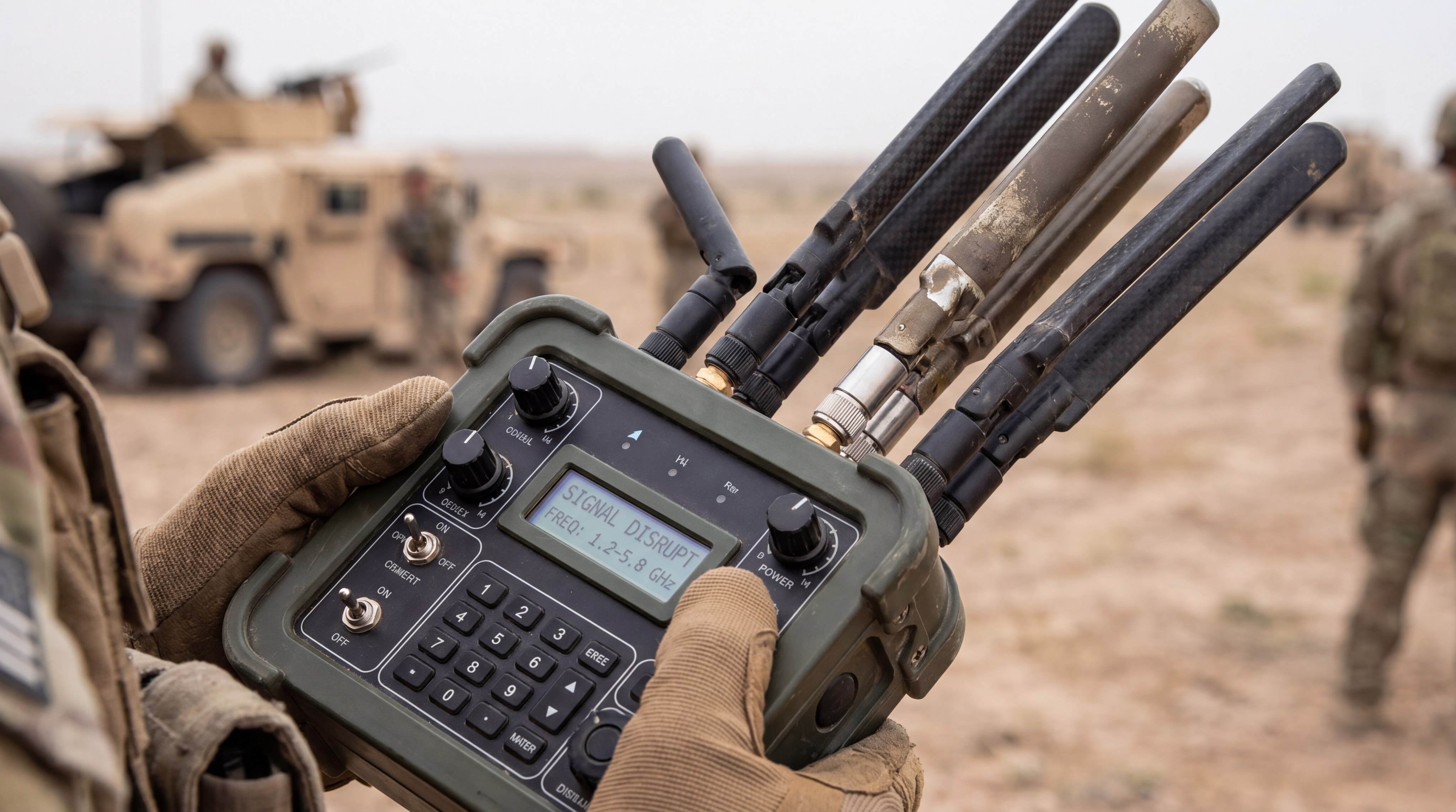
The electromagnetic spectrum is divided into various bands, each allocated for specific uses like cellular data, Wi-Fi, and aviation. Jammers must be precisely tuned to the specific narrow bands used by commercial or military drones to avoid affecting unrelated systems.
Signal-to-noise ratio and receiver saturation
For a drone to receive a command, the signal must be clearer than the background static.
But that’s not all:
- Jammers artificially raise the “noise” to an extreme level.
- This creates a negative signal-to-noise ratio.
- The receiver hardware becomes saturated, preventing any data from being processed.
How does power output determine effective range?
The range of a jammer is directly proportional to its power output and the gain of its transmitting antenna. You need higher power to disrupt a drone that is far away or one that is very close to its original controller.
Key Takeaway: Mastering RF power principles ensures you can create an effective denial zone that scales with the size of the area you need to protect.
| Principle | Technical Metric | Impact on Jamming |
|---|---|---|
| Power | Watts (dBm) | Determines the maximum effective distance. |
| Bandwidth | Hertz (MHz) | Defines how many drone types can be blocked. |
| SNR | Decibels (dB) | Dictates if the disruption will be successful. |
This data summarizes the critical technical variables that dictate the performance and reliability of any electronic countermeasure.
What is a drone jammer using to disrupt signals?
These devices use specialized RF power amplifiers and signal generators to create a wall of interference across the target frequencies. When you ask what is a drone jammer in a technical context, you are describing a high-gain transmission system. It uses specific waveforms designed to be as disruptive as possible to the digital modulation used by UAVs.
Active noise versus barrage jamming techniques
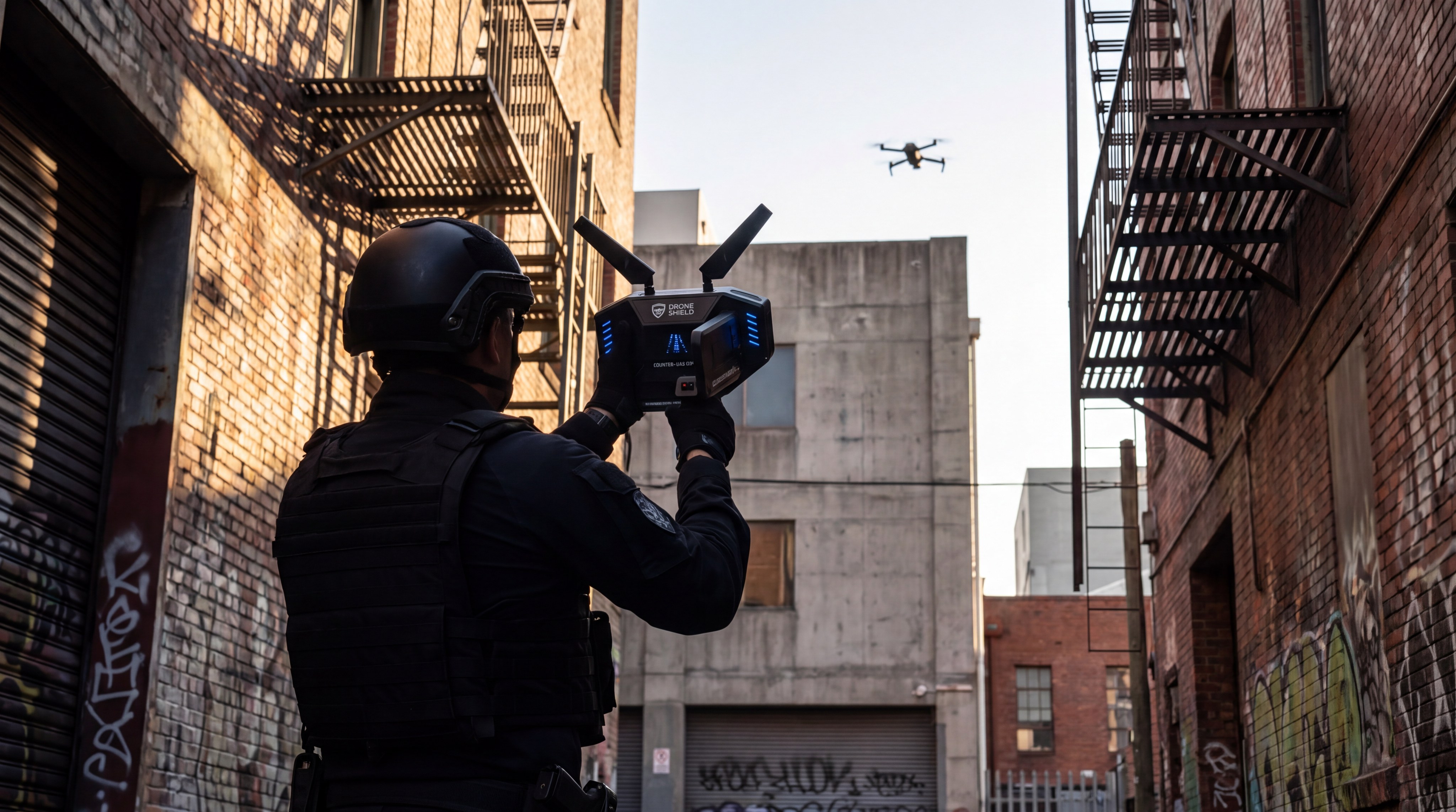
Active noise jamming targets a very specific frequency, while barrage jamming spreads energy across a wide swath of the spectrum. Barrage jamming is often preferred when the exact operating frequency of the intruder is unknown.
Here is the deal:
- Barrage jamming covers more ground but uses more power.
- Spot jamming is efficient but requires precise intelligence.
- Both methods aim to maximize the interference density.
How does frequency-hopping impact jamming?
Modern drones use Frequency-Hopping Spread Spectrum (FHSS) to switch channels rapidly and avoid interference. To counter this, a sophisticated jammer must either sweep the entire band or track the hops in real-time.
The role of RF interference in signal denial
RF interference is the “ammunition” of the electronic warfare world. By generating out-of-phase or high-amplitude waves, the jammer creates a chaotic environment where the drone’s digital packets are corrupted beyond repair.
Key Takeaway: Utilizing diverse jamming techniques like barrage or spot jamming allows you to adapt to the specific evasion tactics used by advanced drones.
| Technique | Efficiency | Application |
|---|---|---|
| Spot Jamming | High | Known single-frequency targets. |
| Barrage Jamming | Low | Multiple drones or unknown frequencies. |
| Sweep Jamming | Medium | Rapidly moving through a frequency range. |
The choice of jamming technique depends heavily on the sophistication of the drone and the urgency of the security threat.
Which frequencies do these devices target?
Most jammers target the common ISM bands of 2.4 GHz and 5.8 GHz, along with various GNSS frequencies like GPS L1. To understand what is a drone jammer, you must look at the global standards for unlicensed wireless communication. Because most commercial drones rely on these bands, a multi-band jammer can neutralize the vast majority of consumer-grade threats.
Disruption of 2.4 GHz and 5.8 GHz control links
The 2.4 GHz band is prized for its range, while 5.8 GHz offers higher bandwidth for HD video transmission.
The kicker is:
- Most drones use both for redundancy.
- Disruption must occur on both bands simultaneously to ensure a total link break.
- Video feed loss often panics an amateur operator, forcing them to retreat.
Why is targeting GPS signals effective?
Drones rely on Global Positioning System (GPS) signals for stability and autonomous navigation. These satellite signals are incredibly weak by the time they reach Earth, making them very easy to overpower with even a low-power jammer.
Managing multi-band frequency disruption
High-end systems can target five or more bands at once, including specialized military frequencies or 4G/5G cellular bands used for long-range control. This comprehensive coverage ensures that no matter how the drone is controlled, it can be stopped.
Key Takeaway: Targeting both the control links and the navigation satellites provides a dual-layer defense that prevents both manual and autonomous flight.
| Target Band | Typical Use | Jamming Effect |
|---|---|---|
| 1.5 GHz | GPS / GLONASS | Loss of position and autonomous flight. |
| 2.4 GHz | Main Control Link | Complete loss of pilot command. |
| 5.8 GHz | Video / Data Feed | Loss of “First Person View” (FPV). |
Blocking these specific bands ensures the drone is isolated from both its operator and its celestial navigation data.
What is a drone jammer design like for field use?
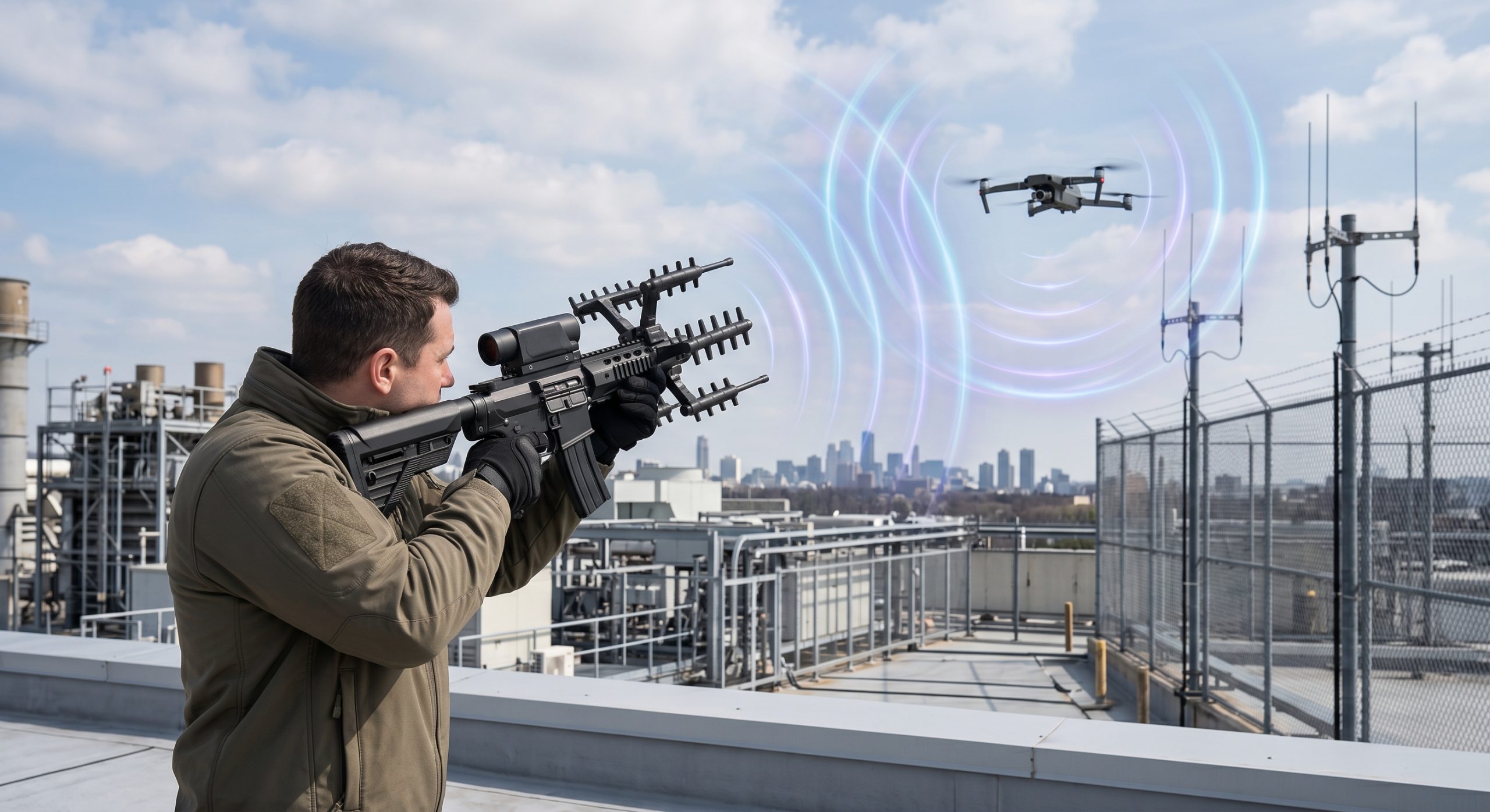
Field-ready designs vary from man-portable “rifles” to large, fixed installations mounted on buildings or vehicles. When you explore what is a drone jammer, you see a focus on ergonomics and rapid deployment. A security guard needs to be able to aim and activate the device within seconds of a visual sighting.

Handheld versus stationary installation benefits
Handheld “jammer guns” are mobile and allow for directional targeting, while stationary systems provide 24/7 automated protection for a specific perimeter. Stationary systems often use higher power levels because they are connected to a permanent power grid.
Portable wearable solutions for mobile security
Wearable jammers are designed for soldiers or VIP security teams who are constantly on the move. These are often omnidirectional, creating a “protective bubble” around the user.
Consider this:
- They are lightweight and battery-powered.
- They offer passive protection without needing to aim.
- They are ideal for protecting convoys or foot patrols.
How do mobile jammer platforms operate?
Mobile platforms can be mounted on trucks or even other drones to provide a dynamic counter-UAS (C-UAS) response. These systems often include their own power generators and cooling units to handle long-duration jamming missions.
Key Takeaway: Choosing between handheld and stationary designs depends on whether you need targeted precision or continuous area-wide denial.
| Design Type | Portability | Effective Range |
|---|---|---|
| Jammer Gun | High | Up to 1.5 km (Directional) |
| Fixed Mast | None | Up to 5 km (Omni/Directional) |
| Wearable | Maximum | Up to 500m (Omni) |
This comparison highlights how different physical formats serve various tactical needs in the field of counter-drone security.
How is this technology deployed in the field?
Deployment involves placing sensors and jammers in strategic locations to maximize coverage and minimize “blind spots” in the airspace. Investigating what is a drone jammer deployment shows that positioning is everything. You must consider the topography, the height of buildings, and the likely approach paths of a hostile drone.
Directional versus omnidirectional strategies
Directional jammers focus all their energy into a narrow cone, allowing for longer range and less interference with friendly systems. Omnidirectional antennas broadcast in all directions, which is better for “blanket” coverage but uses more power.
The best part?
- Directional beams can “pick off” a drone miles away.
- Omnidirectional systems create a “no-fly zone” around a stadium or airport.
- A mix of both provides the most robust defense.
Protecting critical infrastructure from above
Airports and power plants often install jammers on high towers to create a clear line of sight to the horizon. This prevents drones from hiding behind obstacles or terrain as they approach the sensitive core of the facility.
Tactical positioning for maximum airspace denial
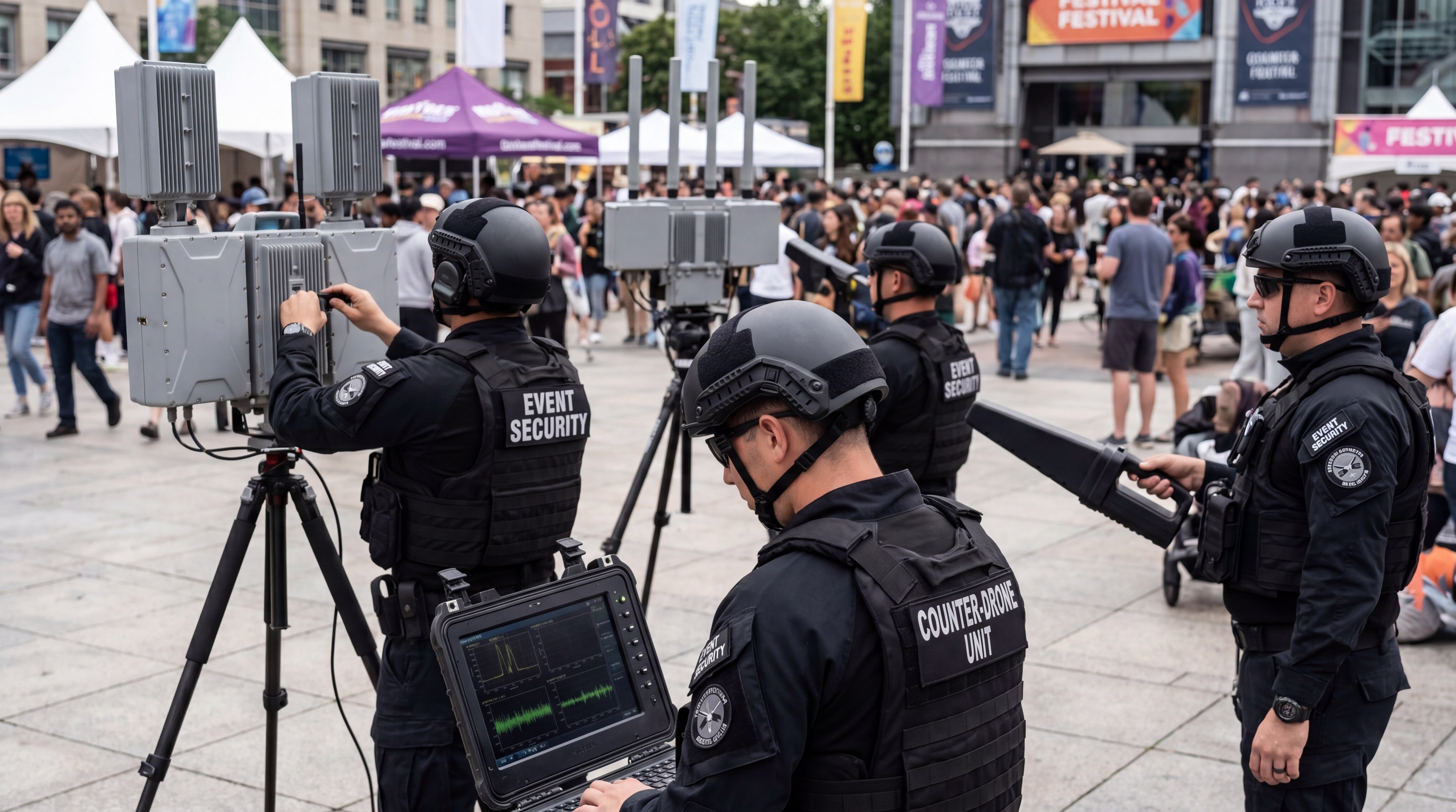
Tactical teams use jammers in conjunction with detection systems to create a responsive defense. Once a drone is spotted by radar, the jammer is pointed at the coordinates to initiate immediate suppression.
Key Takeaway: Combining directional and omnidirectional systems allows you to create a comprehensive shield that stops drones from any angle of approach.
| Deployment Strategy | Ideal Scenario | Key Advantage |
|---|---|---|
| Perimeter Shield | Border Control | Constant, automated denial. |
| Point Defense | VIP Protection | Highly mobile and reactive. |
| Sector Denial | Military Base | High-power, long-range blocking. |
Strategic placement ensures that your jamming assets are utilized efficiently to deny unauthorized access to sensitive airspace.
Is there a difference between jamming and spoofing?
Yes, jamming is the act of blocking a signal with noise, while spoofing is the act of sending a fake signal to trick the drone. When you look at what is a drone jammer, you are seeing a denial tool. Spoofing is a manipulation tool that can actually take control of the drone’s flight path by feeding it false GPS coordinates.
How does GPS spoofing take over flight paths?
Spoofing works by mimicking the timing and signal structure of GPS satellites but with slightly altered data.
Think about it:
- The drone believes it is in a different location.
- It may try to “correct” its position, flying right into a trap.
- This is much more technically complex than simple jamming.
Comparing signal denial with signal manipulation
Signal denial (jamming) is “brute force”—it just turns the lights off. Signal manipulation (spoofing) is a “trojan horse”—it lets the drone keep flying but on your terms. Jamming is generally safer for the user as it is less likely to be detected as a cyber-attack.
When is spoofing preferred over jamming?
Spoofing is preferred when you want to capture the drone intact or redirect it to a safe landing zone far from your location. However, spoofing requires significantly more computing power and advanced software to execute successfully.
Key Takeaway: While jamming is simpler and more reliable for immediate denial, spoofing offers the advanced ability to redirect threats safely.
| Method | Technical Goal | Complexity |
|---|---|---|
| Jamming | Signal Denial | Low to Medium |
| Spoofing | Signal Deception | Very High |
| Protocol Manipulation | Command Hijacking | Extreme |
This table clarifies why most security teams rely on jamming for immediate threat mitigation while reserving spoofing for advanced scenarios.
What is a drone jammer restricted by in law?
A drone jammer is restricted by strict telecommunications laws in almost every country, usually limiting its use to military and government agencies. When researching what is a drone jammer, you will quickly find that for a civilian, owning one is often illegal. This is because radio waves do not stop at property lines; a jammer meant for your backyard could accidentally block a neighbor’s Wi-Fi or emergency calls.
Legal constraints for civilian and commercial use
In the United States, the FCC prohibits the use, marketing, and sale of jamming equipment to the general public.
Here is the kicker:
- Fines for illegal use can reach hundreds of thousands of dollars.
- Using a jammer near an airport can result in criminal charges.
- The law protects the integrity of the public airwaves.
Why are military exemptions necessary?
The military requires these tools for force protection in combat zones where drones are used as improvised explosive devices. These exemptions allow for the development of high-power systems that would be far too dangerous for domestic urban use.
Risks to emergency and aviation communications
Jammers can interfere with the “Life and Safety” bands used by police, fire departments, and ambulance services. They can also disrupt the critical navigation and communication systems used by commercial airliners, potentially leading to catastrophic accidents.
Key Takeaway: Understanding the legal landscape ensures that you remain compliant while utilizing authorized defensive technologies for legitimate security needs.
| Regulatory Body | Region | General Stance |
|---|---|---|
| FCC | USA | Strictly Prohibited for Civilians. |
| ETSI | Europe | Highly Regulated / Restricted. |
| ITU | Global | Coordinates frequency protections. |
Navigating these regulations is essential for any organization looking to deploy counter-UAS technology responsibly and legally.
How are jammers integrated into defensive webs?
Jammers serve as the “kinetic” end of a multi-layered security system that first detects and tracks threats before engaging. When you consider what is a drone jammer, you must see it as one piece of a larger puzzle. A jammer is useless if you don’t know a drone is coming, which is why integration with radar and RF sensors is vital.
Pairing RF jammers with radar and sensors
Radar can detect drones that are flying autonomously without a radio link, while RF sensors can “hear” the drone’s transmissions.
But that’s not all:
- Sensors provide the frequency and location.
- The system automatically slews the jammer to the target.
- This creates an automated “detect-and-neutralize” loop.
Layered counter-UAS protection models
A layered defense uses different technologies for different ranges. Long-range radar finds the threat, medium-range cameras identify it, and short-range jammers or nets stop it. This ensures that a single failure doesn’t leave you vulnerable.
Automating the detection and neutralization loop
Modern C-UAS systems use AI to identify drone signatures and automatically activate the jammer. This removes the “human in the loop” delay, which is critical when facing fast-moving FPV drones or swarms.
Key Takeaway: Integrating jammers into a sensory network transforms them from manual tools into a powerful, automated shield for your facility.
| Component | Role | Action |
|---|---|---|
| Radar / RF Sensor | Detection | Identifies the threat. |
| PTZ Camera | Identification | Verifies the drone type. |
| RF Jammer | Neutralization | Disrupts the command link. |
This structural overview shows how a modern defensive web functions to provide 360-degree protection against aerial intruders.
What does the future of C-UAS technology look like?
The future involves cognitive jammers that use AI to adapt to new frequencies and the rise of high-energy lasers for physical destruction. When you look at the evolution of what is a drone jammer, it is becoming smarter and more localized. Tomorrow’s systems will be able to pinpoint a single drone in a crowd without affecting any other devices.
AI-driven adaptive jamming systems
Future systems will use machine learning to “learn” the specific signal patterns of new drone models.
Think about it:
- They will update their jamming waveforms in real-time.
- They will bypass the encryption of military-grade links.
- They will be “software-defined,” meaning they get better over time.
Emerging threats from autonomous drone swarms
Swarms consist of hundreds of drones flying together, which can overwhelm a single jammer. The future of defense involves “cloud jamming”—using a network of coordinated disruptors to block an entire swarm simultaneously.
Transitioning toward high-energy laser solutions
When electronic jamming isn’t enough, high-energy lasers (HEL) provide a way to physically burn the drone’s electronics or structure. Lasers offer a “silent” kill that is effective against drones that don’t rely on radio links at all.
Key Takeaway: Staying ahead of the technological curve ensures that your security infrastructure can counter even the most advanced autonomous and swarming threats.
| Future Trend | Technology | Impact |
|---|---|---|
| Cognitive Jamming | AI / Machine Learning | Adapts to frequency-hopping. |
| Directed Energy | High-Power Lasers | Physical destruction of drones. |
| Networked Defense | Mesh Sensors | Protects massive urban areas. |
As drone technology advances, so too must the electronic and physical countermeasures used to keep our skies and ground assets secure.
FAQ
Can I use a drone jammer to stop a neighbor’s drone?
No. In almost all jurisdictions, using a jammer for personal disputes is illegal and carries heavy federal penalties.
What’s the best way to detect a drone before jamming it?
A combination of RF sensors and acoustic detectors is generally the most effective way to identify a drone’s presence early.
How do I know if a drone is being jammed?
It depends. If the drone stops moving, starts to land, or flies straight back to its origin, it is likely reacting to a link disruption.
Is it possible for a drone to ignore a jammer?
Yes. Drones that are flying completely autonomously via pre-programmed GPS waypoints may not be affected by control-link jamming.
Will a drone jammer interfere with my Wi-Fi?
Yes. Since many drones and Wi-Fi networks share the 2.4 GHz and 5.8 GHz bands, a jammer will likely disrupt nearby internet connections.
Conclusion
Securing your airspace requires a deep understanding of electronic warfare principles and the tactical deployment of signal disruption technology. We have explored how these devices solve the critical problem of unauthorized aerial surveillance and physical threats by severing the data links that modern drones depend on. By integrating advanced RF amplification with smart detection sensors, you can build a defensive perimeter that is both responsive and reliable. If you are ready to enhance your facility’s security and protect against the growing risk of UAV intrusions, contact us today to discuss professional integration. We provide the high-power RF platforms and engineering expertise needed to reclaim your privacy and ensure operational continuity. Our vision is a world where critical infrastructure is shielded by an invisible, impenetrable barrier of electronic intelligence, and we are committed to providing the hardware that makes that security a reality.
Authorized RF engineering and compliance review
For regulated RF systems, this page should be used as an engineering and compliance review path, not as a public deployment checklist. CorelixRF starts with authorization status, operating region, frequency plan, output limit, antenna interface, safety controls, thermal limits and acceptance documents.
- RFQ checklist – send the data buyers usually forget, including band, power, duty cycle, interface and test standard
- delivery documentation – check what documents can support incoming inspection, FAT review and long-term maintenance
- quality and certification review – review the quality and compliance evidence before the project moves into procurement
- RF front-end platform – compare the RF chain as a system instead of selecting one isolated module
- RF configurator – turn frequency, power, thermal and interface requirements into a first configuration brief
- case studies – review similar engineering paths before sending an RFQ
- engineering contact – send the application notes, block diagram or target specification to engineering sales
This keeps the discussion inside lawful, authorized RF programs while still giving procurement teams a clear way to request amplifier, antenna, SDR source, documentation and factory review.
Authorized RF System Review Path
For authorized counter-UAS RF reviews, connect operational requirements to RF power amplifier platform selection, RF front-end integration and antenna/load planning. Share frequency bands, output power, duty cycle, cooling, enclosure limits, VSWR protection, compliance boundaries and validation evidence through the RF inquiry form.