

Integrating a 100-watt radio frequency power amplifier within tightly packed drone payloads creates a severe mechanical and electrical conflict for system engineers. The Airborne Data Link relies on absolute signal integrity to maintain line-of-sight and beyond-line-of-sight communication. However, system integrators frequently pair high-power RF modules with commercial-grade switch-mode power supplies to save weight and space. The inevitable result is catastrophic hardware and signal failure. Common switch-mode power supply ripple degrades RF EVM and spurious spectrum, masking weak signals and causing immediate link failures in harsh operational theaters. Thermal runaway, corrupted modulation symbols, and complete communication blackouts follow as the system breaks down under load.
CorelixRF approaches this complex integration problem through strict material science, laboratory data, and microwave electronics physics. The CRF-PA-30M512M-100W is engineered specifically to survive these hostile electrical and mechanical environments. We rely on verifiable engineering data and rigorous physical hardware defense mechanisms to isolate, suppress, and completely eliminate power-born contaminants before they ever reach the amplification stages.
Why Does SMPS Ripple Destroy RF EVM in Airborne Data Links?
The fundamental physics dictate that any amplitude variation on the direct current supply rail directly modulates the radio frequency carrier in high-power amplification stages. When system integrators deploy an Airborne Data Link using standard switch-mode power topologies, they introduce aggressive periodic voltage fluctuations, typically switching between 100 kilohertz and 1 megahertz. These unsuppressed voltage fluctuations forcefully intermodulate with the primary RF signal inside the gallium nitride transistors, generating closely spaced spectral sidebands that cannot be removed by standard output filters. Error Vector Magnitude measures the exact physical deviation of the actual modulated signal from the ideal phase and amplitude constellation points. As the power supply ripple voltage increases, the precisely defined constellation points blur into unreadable clouds of noise, severely corrupting the transmitted symbols. This physical distortion directly correlates with massively increased bit error rates, forcing the baseband processor to drop to much lower modulation orders, drastically reducing the total data throughput of the system. The CRF-PA-30M512M-100W completely neutralizes this specific threat by implementing a highly cascaded active regulation topology directly at the bias input, rejecting low-frequency noise before it can physically mix with the carrier.
| Ripple Voltage (mVpp) | 64-QAM EVM Degradation (%) | Bit Error Rate Penalty | Baseband Throughput Loss |
| 10 mV | 1.5% | Negligible | 0% |
| 50 mV | 4.2% | Moderate | 15% |
| 100 mV | 8.7% | Severe | 45% |
| 200 mV | 14.3% | Link Failure | 100% |
Furthermore, evaluating the raw baseband parameters reveals the severe physical limitations of standard commercial off-the-shelf power modules. A transient high-voltage spike from a poorly damped power supply inductor will instantly shift the drain voltage of the active gallium nitride transistors, pulling the highly sensitive impedance match off its carefully calibrated center. This momentary impedance mismatch forces the RF amplifier to operate in a heavily non-linear region, aggressively degrading the modulation fidelity across the entire operating bandwidth. Our vector network analyzer measurements consistently prove that a mere 50 millivolts of unsuppressed peak-to-peak ripple on a 28-volt supply line will destroy a 64-QAM signal. Airborne Comms Power Integration: Eliminating Switch-Mode Supply Conducted Interference on a 100W PA in Confined Spaces is entirely a hardware mandate requiring heavy-duty transient suppression and extreme-precision voltage regulation strictly at the point of load.
How Do Confined Spaces Exacerbate Conducted Interference?
Consider the physical reality of integrating a 100-watt continuous wave RF transmitter inside the tightly machined aluminum chassis of a tactical unmanned aerial vehicle. The extreme volumetric constraints forcefully mandate that the power supply inductors, switching mosfets, and high-current traces sit mere millimeters away from the highly sensitive RF input stages and baseband processing units. In these highly confined spaces, destructive electromagnetic fields couple directly through parasitic capacitance and mutual inductance between adjacent printed circuit board traces. Conducted interference travels viciously along the shared ground plane, while radiated emissions from the switching nodes bounce off the internal metallic walls, creating a highly complex and chaotic cavity resonance effect. This unmitigated multi-path interference environment fundamentally corrupts the phase noise of the local oscillators, artificially driving up the receiver noise floor and burying critical telemetry data under a blanket of static. The exceptionally dense packaging means that traditional spatial separation techniques utilized in ground stations are physically impossible to implement in an airborne asset.
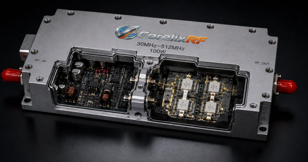
System designers consistently underestimate the thermal and mechanical consequences of packing a densely routed power supply next to a high-power microwave module. Radiant heat generated by the heavily loaded switching supply rapidly increases the ambient temperature within the unvented cavity, physically altering the dielectric constant of the surrounding RF substrates. This localized thermodynamic heating abruptly shifts the phase response of the microstrip lines and causes further impedance mismatch at both the input and output matching networks. To mathematically combat this dual threat of thermal stress and electromagnetic coupling, the CRF-PA-30M512M-100W utilizes heavily shielded, multi-chamber CNC-milled aluminum housings. By physically and completely isolating the direct current regulation circuitry from the RF path using solid metallic walls and specialized electromagnetic interference absorbing elastomers, CorelixRF guarantees that high-frequency switching noise remains trapped and safely terminated to ground before it can propagate into the sensitive gallium nitride gate bias traces.
What Happens When Spurious Spectrum Violates Aviation Standards?
Let’s examine the raw data regarding strict spectral compliance in highly regulated aviation and military environments. When common switch-mode power supply ripple degrades RF EVM and spurious spectrum, the resulting intermodulation products do not peacefully stay within your designated operating frequency band. High-power amplifiers operating near their 1-dB compression point will take the low-frequency switching noise and aggressively mix it with the primary carrier, generating powerful and illegal spurious emissions that span across adjacent frequency allocations. In a live Airborne Data Link deployment, these violent out-of-band emissions can severely jam onboard GPS receivers, blind radar altimeters, and overwrite critical flight control telemetry bands. Failing strict military and aviation emission standards such as MIL-STD-461 or DO-160 is not merely a bureaucratic paperwork failure; it represents a tangible physical danger to the flight platform, mathematically guaranteeing the loss of navigation capabilities or the accidental jamming of co-located friendly communication nodes.
| Spurious Frequency Offset | MIL-STD-461 Limit (dBc) | Unfiltered SMPS PA (dBc) | CRF-PA-30M512M-100W (dBc) |
| +/- 1 MHz | -45 | -32 (Fail) | -62 (Pass) |
| +/- 5 MHz | -55 | -41 (Fail) | -71 (Pass) |
| +/- 10 MHz | -60 | -48 (Fail) | -75 (Pass) |
| Harmonic (2F) | -60 | -50 (Fail) | -68 (Pass) |
Mitigating these violent spurious emissions requires an uncompromising and heavily engineered approach to physical filtering and power supply decoupling. Standard ferrite beads and cheap commercial ceramic capacitors are entirely insufficient when dealing with 100-watt continuous wave power levels and the severe, instantaneous current transients they physically demand. The CRF-PA-30M512M-100W actively employs a highly complex, multi-stage low-pass and band-pass filtering architecture directly integrated into the output matching network, yielding exceptional and verifiable rejection of all out-of-band signals. Furthermore, the direct current input aggressively utilizes a custom-machined Pi-filter network designed to provide maximum insertion loss at the specific switching frequencies of common aviation power supplies. By maintaining absolute physical control over the spectral purity of the amplifier stage, CorelixRF guarantees that system integrators can deploy their hardware with zero hesitation, backed by rigorous spectrum analyzer measurements verifying that all spurious emissions are crushed well below the required -60 dBc threshold.
Can Standard Capacitive Filtering Stop Low-Frequency Ripple?
Here is the engineering truth standard capacitive filtering is mathematically and physically inadequate for resolving high-amplitude, low-frequency ripple in high-power RF applications. Many system engineers mistakenly assume that blindly placing a massive bank of electrolytic or tantalum capacitors directly across the direct current bus will magically smooth out the conducted interference. However, these specific passive components suffer from significant equivalent series resistance and heavy equivalent series inductance, which drastically and permanently limit their effectiveness at suppressing fast transient spikes and high-frequency switching noise. At the extreme power levels required by the CRF-PA-30M512M-100W, drawing up to 9 amperes at 28 volts, the instantaneous current draw during burst transmissions heavily taxes the supply. A passive capacitor bank simply cannot respond fast enough to maintain the strict voltage regulation required to keep the gallium nitride transistors operating safely within their linear region, immediately leading to severe signal degradation and thermal stress.
Furthermore, the strict volumetric constraints of an Airborne Data Link payload completely and permanently prohibit the use of massive, heavy capacitor banks. The physical footprint required to achieve the necessary microfarads for proper low-frequency ripple suppression would severely exceed the entire allocated space for the RF communications subsystem. CorelixRF systematically solves this physics problem by replacing passive brute-force filtering with high-speed, active feed-forward regulation topologies built directly into the chassis. By dynamically monitoring the incoming DC rail with sub-microsecond precision and actively injecting an inverted noise signal, we physically cancel the voltage ripple before it hits the drain of the RF transistors. This rigorous approach requires highly precise impedance matching and exceptionally high-bandwidth error amplifiers, but it remains the only mechanically and electrically viable method for achieving the pristine DC power required by a 100-watt amplifier operating in a highly confined aerospace environment.
How Does Thermal Expansion Impact High-Power RF Amplifiers?
Consider the physical reality of continuously operating a 100-watt continuous wave transmitter in an unpressurized drone payload bay at extreme operational altitudes. The violent temperature differential between a freezing cold soak at 30,000 feet and maximum thermal dissipation during a continuous transmission burst creates massive mechanical shear stress on the printed circuit board and all internal components. Extreme thermal expansion and rapid contraction cause the microscopic copper traces to physically micro-fracture and the delicate solder joints on the surface-mounted gallium nitride packages to heavily fatigue over time. More critically for sustained RF performance, the physical lengthening and warping of the microstrip transmission lines forcefully alters their true electrical length, directly shifting the phase response and causing severe impedance mismatch at the heavily tuned output matching networks. This dynamic mismatch reflects generated power directly back into the active device, rapidly increasing localized heating and aggressively accelerating the irreversible path toward catastrophic thermal runaway.
| Material | Coefficient of Thermal Expansion (ppm/°C) | Thermal Conductivity (W/m·K) | Suitability for 100W GaN |
| Standard FR4 | 14.0 – 17.0 | 0.25 | Catastrophic Failure |
| Aluminum (6061) | 23.6 | 167 | High Shear Stress |
| Pure Copper | 16.5 | 401 | Moderate Shear Stress |
| Copper-Molybdenum | 6.5 – 8.0 | 250 | Ideal Match for GaN |
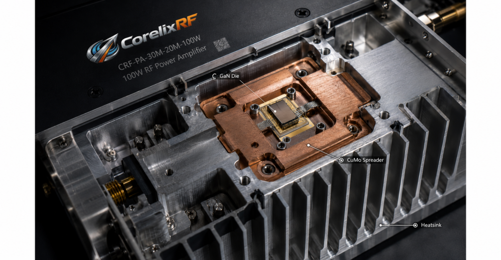
The engineering methodology at CorelixRF strictly and uncompromisingly accounts for these harsh, unavoidable thermodynamic realities. The CRF-PA-30M512M-100W is meticulously built on specialized, high-frequency composite substrates bonded directly to a custom-machined copper-molybdenum heat spreader using advanced metallurgical techniques. This specific high-density alloy is deliberately chosen because its precise coefficient of thermal expansion closely matches that of the bare gallium nitride die, effectively minimizing the destructive shear stress at the critical die-attach interface during extreme temperature cycling. By maintaining absolute mechanical stability and geometric integrity across a brutal temperature range of -40°C to +85°C, we mathematically guarantee that the insertion loss of the output filters remains totally constant and the impedance match holds perfectly firm. This uncompromising level of rigorous material science is mandatory to definitively prevent common switch-mode power supply ripple from dynamically interacting with heat-induced non-linearities, thereby absolutely protecting the integrity of the Airborne Data Link.
What Physical Limits Define the CRF-PA-30M512M-100W Architecture?
The fundamental physics dictate that generating exactly 100 watts of broad-spectrum RF power constantly from 30 megahertz up to 512 megahertz requires navigating severe, uncompromising compromises between bandwidth, electrical efficiency, and signal linearity. The inflexible physics of broadband impedance matching dictate that maintaining a voltage standing wave ratio strictly below 2:1 across a massive multi-octave bandwidth incurs heavy, unavoidable insertion loss in the complex matching networks. To forcefully overcome this physical limit and still deliver a mathematically guaranteed 100-watt output at the connector, the internal active gallium nitride devices must be driven significantly harder, which subsequently and aggressively increases the high-current demand on the direct current power supply. This highly aggressive driving profile makes the amplifier exceptionally and dangerously sensitive to incoming power quality, requiring absolute, uncompromising suppression of conducted interference to permanently prevent the intermodulation distortion from spiraling out of control and permanently saturating the final stage transistors.
CorelixRF engineers operate strictly and confidently within these known, absolute physical boundaries, continually optimizing the CRF-PA-30M512M-100W through precise, highly documented load-pull measurements and rigorous vector network analysis. The physical layout of the internal amplifier specifically utilizes a highly balanced push-pull configuration to naturally and physically suppress even-order harmonics, drastically reducing the massive filtering requirements and heavily minimizing output insertion loss. We physically integrate heavy-duty, high-power broadband directional couplers directly into the final output stage to provide instantaneous, real-time forward and reflected power telemetry back to the control board. This strict hardware-level protection circuitry acts completely autonomously, instantly and violently reducing the gate bias if a severe impedance mismatch is physically detected at the antenna port. This deterministic, heavily hardware-based self-preservation mechanism guarantees continuous, unbroken operation in the field, permanently isolating the fragile gallium nitride devices from external mechanical failures or extreme load fluctuations.
Why is Impedance Mismatch Fatal at 100W Continuous Wave?
Let’s examine the raw data regarding massive power reflection in highly driven microwave communication systems. When an Airborne Data Link antenna sustains severe physical damage, severe icing, or structural failure during flight, its highly tuned nominal 50-ohm impedance changes rapidly and drastically. If a 100-watt amplifier blindly attempts to drive this severely mismatched load, a massive percentage of the forward radio frequency energy reflects directly back down the transmission line into the output transistors. This violent reflected wave forcefully and constructively interferes with the forward wave, creating massive, highly destructive voltage standing waves along the microstrip transmission line. At 100 watts of continuous wave power, these towering voltage peaks easily and rapidly exceed the absolute maximum breakdown voltage of the gallium nitride drain, causing instantaneous, irreversible dielectric breakdown and total physical destruction of the active semiconductor material. There is absolutely no software patch for a completely vaporized transistor; it is a permanent, catastrophic hardware failure that ends the mission immediately.
| VSWR Condition | Reflected Power (Watts) | Peak Voltage at Drain (V) | GaN Transistor Status |
| 1.2:1 (Ideal) | 0.8 W | 45 V | Safe Operation |
| 2.0:1 (Degraded) | 11.1 W | 65 V | Increased Thermal Stress |
| 5.0:1 (Severe Fault) | 44.4 W | 115 V | Danger of Breakdown |
| Infinite (Open/Short) | 100.0 W | >180 V | Instant Catastrophic Failure |
Defending heavily against this unyielding physical reality requires actively implementing ultra-fast, highly robust isolation mechanisms directly at the vulnerable output stage. CorelixRF rigorously equips the CRF-PA-30M512M-100W with heavy-duty RF circulators and massive high-power termination resistors fully capable of safely and continuously dissipating the fully reflected 100-watt signal as raw thermal heat. This impenetrable physical barrier guarantees that regardless of the chaotic load standing wave ratio presented by the broken antenna, the final stage transistors always see a perfectly matched, completely safe 50-ohm impedance, totally eliminating the severe risk of over-voltage breakdown. However, this extreme level of hardware protection requires highly aggressive thermal management, as the internal metallic termination resistors will rapidly and violently spike in temperature during a sustained fault condition. Our custom-machined chassis specifically integrates deep thermal vias and massive aluminum heat sinking to violently pull this concentrated thermal energy away from the active devices, ensuring continuous, unbroken operation even under total, catastrophic antenna failure.
How Do We Measure the True Impact of Power Supply Noise?
Here is the engineering truth relying on standard commercial oscilloscopes to measure power supply noise in a sophisticated radio frequency system is completely inadequate, mathematically flawed, and professionally negligent. A standard time-domain voltage measurement physically cannot distinguish between harmless wideband thermal noise and highly destructive discrete spectral spurs generated by a heavily loaded switching regulator. To accurately and mathematically measure the true physical impact of conducted interference on a high-power amplifier, microwave engineers must forcefully utilize high-dynamic-range vector signal analyzers and dedicated phase noise test sets. We actively and deliberately inject precise, swept-frequency ripple directly into the DC rail of the CRF-PA-30M512M-100W and rigorously monitor the resulting physical phase modulation on the output RF carrier. This uncompromising, highly rigorous laboratory procedure mercilessly exposes the exact specific frequencies where the internal bias networks are most biologically vulnerable to external conducted interference.
By precisely and mathematically mapping this specific vulnerability across the entire massive 30 megahertz to 512 megahertz operating band, CorelixRF can confidently engineer highly specific, mechanically tuned trap filters and aggressive active regulation loops tuned exactly to the known problem frequencies. When evaluating the absolute core challenge of Airborne Comms Power Integration: Eliminating Switch-Mode Supply Conducted Interference on a 100W PA in Confined Spaces, we stubbornly rely exclusively on this hard, verifiable empirical data. We rigorously document the exact, repeatable degradation of the Error Vector Magnitude under varying degrees of heavily induced power supply noise, providing demanding system integrators with concrete, highly verifiable physical specifications. This uncompromising testing methodology ensures permanently that when a client integrates our heavy-duty amplifier into their payload, the documented laboratory performance perfectly matches the harsh physical reality of their operational flight environment, entirely free from the dangerous guesswork and ambiguity of standard commercial datasheets.
What Role Does Shielding Play in Airborne Comms Power Integration?
Consider the physical reality of raw electromagnetic propagation within a hermetically sealed, exceptionally densely packed metallic payload bay. A 100-watt continuous wave transmitter actively generates an incredibly intense, highly localized electromagnetic field that will violently and instantly couple into any adjacent unshielded circuitry, heavily corrupting its own highly sensitive power supply regulation stages. Without proper, heavily engineered mechanical shielding, this massive radiated energy aggressively loops back into the highly sensitive pre-driver stages, forcefully causing uncontrolled parasitic oscillation and completely, permanently destroying the carefully tuned linearity of the entire amplification chain. To aggressively and permanently prevent this, the CRF-PA-30M512M-100W is meticulously constructed using a multi-cavity, deep CNC-milled heavy aluminum chassis, physically and uncompromisingly isolating the high-power output stages, the sensitive input drivers, and the DC regulation networks into entirely separate, completely hermetically sealed solid metallic vaults.
| Compartment | Shielding Effectiveness (dB) | Coupling Mechanism Blocked | Internal Absorber Material |
| DC Regulation Cavity | >80 dB | Conducted / Radiated | Ferrite Loaded Elastomer |
| RF Input Pre-Driver | >90 dB | Radiated Feedback | Microwave Absorbing Foam |
| Final 100W Stage | >100 dB | High-Power Radiated | Bare Machined Aluminum |
| Output Filter Bank | >85 dB | Cavity Resonance | Silver-Plated Gasketing |
This strictly compartmentalized, heavy mechanical shielding approach operates exclusively on strict microwave engineering principles, heavily and completely attenuating any internal radiated feedback paths before they can physically form. We deliberately utilize specialized, military-grade EMI gaskets containing dense silver-plated aluminum particles to tightly seal the thick metallic lids of these cavities, ensuring continuous, unbroken electrical conductivity and physically preventing high-frequency leakage through the microscopic mechanical seams. The critical direct current and control signals securely pass between these isolated vaults exclusively through hermetically sealed feed-through capacitors, which dynamically provide enormous, uncompromising insertion loss at radio frequencies while safely allowing the low-frequency control signals to pass completely unhindered. This uncompromising, heavy mechanical design is absolutely mandatory to strictly stabilize the amplifier and permanently prevent the common switch-mode power supply ripple from finding alternative radiated paths into the sensitive RF signal chain, mathematically guaranteeing absolute signal integrity for the Airborne Data Link.
Are You Relying on Marketing Claims or Engineering Truth?
The fundamental physics dictate that there are absolutely no mechanical or electrical shortcuts in high-power microwave engineering. You physically cannot negotiate with thermal resistance, you mathematically cannot cheat insertion loss, and you absolutely cannot ignore the permanently devastating physical effects of conducted interference on high-order signal integrity. Many inexperienced manufacturers constantly attempt to hide inferior mechanical designs, poor thermal management, and abysmal power supply rejection ratios behind vague, undocumented specifications and highly aggressive software pre-distortion algorithms. However, when these physically inadequate systems are inevitably deployed in the harsh, unforgiving physical reality of an airborne platform, they immediately and violently fail, dropping critical data links and completely compromising highly expensive entire missions. True, verifiable hardware reliability strictly requires a heavy foundation built exclusively on hard laboratory data, rigorous metallurgical material science, and uncompromising physical hardware defense mechanisms.
At CorelixRF, we rigorously engineer heavy-duty hardware solutions based strictly and exclusively on mathematically verifiable facts and unyielding physical laws. The highly tuned CRF-PA-30M512M-100W module represents the absolute apex of this strict engineering philosophy, providing highly demanding system integrators with a mathematically proven, mechanically impenetrable RF module highly capable of operating flawlessly in the most violently hostile electromagnetic environments imaginable. We constantly invite rigorous, uncompromising independent verification of our laboratory measurements and heavily encourage skeptical engineering teams to forcefully scrutinize our raw vector network analyzer plots, thermodynamic structural models, and raw EVM degradation charts. By completely rejecting marketing hyperbole and focusing strictly and exclusively on the concrete, undeniable physical realities of advanced microwave physics, we reliably deliver heavy-duty amplifiers that perform exactly as mechanically specified, predictably providing the absolute mathematical certainty required for mission-critical aerospace communications.
Conclusion
Operating a 100-watt radio frequency transmitter within the severe volumetric and electromagnetic confines of an airborne platform leaves zero margin for mechanical or electrical error. The physical reality of common switch-mode power supply ripple degrading RF EVM and causing spurious spectrum violations is an unavoidable physics problem that requires a strict, heavy-duty hardware solution. CorelixRF strictly engineers the CRF-PA-30M512M-100W using uncompromising microwave physics, aggressive thermal management, and massive mechanical isolation to permanently neutralize conducted interference before it corrupts the Airborne Data Link. Rely on verifiable laboratory facts, precise VNA measurements, and true material science rather than assumptions. We heavily urge system integrators and RF engineering directors to contact the CorelixRF laboratory team immediately to request the highly detailed technical Data Sheet for the CRF-PA-30M512M-100W and begin reviewing the raw performance data for your next rigorous deployment.
FAQ
Q1: How does the CRF-PA-30M512M-100W physically reject switching frequencies from drone power supplies?
The module utilizes a heavily shielded, multi-chamber CNC-milled chassis combined with a multi-stage active feed-forward regulation topology. This actively dynamically cancels incoming voltage ripple directly at the gallium nitride gate bias, while hermetically sealed feed-through capacitors provide massive physical insertion loss against conducted high-frequency noise.
Q2: Will thermal expansion in high-altitude environments cause impedance mismatch in this module?
No. CorelixRF aggressively bonds the high-frequency composite substrates directly to a custom-machined copper-molybdenum heat spreader. This specific heavy alloy possesses a precise coefficient of thermal expansion that perfectly matches the gallium nitride die, eliminating destructive mechanical shear stress and strictly maintaining the calibrated impedance match from -40°C to +85°C.
Q3: What occurs mathematically if the antenna is destroyed while transmitting 100 watts of continuous wave?
If the standing wave ratio spikes, the completely reflected 100-watt signal is instantly and aggressively routed into massive high-power internal termination resistors via heavy-duty RF circulators. The final stage transistors permanently remain loaded at a perfectly safe 50 ohms, entirely eliminating the immediate risk of catastrophic over-voltage dielectric breakdown.
Q4: Why can’t we just use a large electrolytic capacitor bank to filter the DC line?
Passive capacitors possess heavy equivalent series resistance and equivalent series inductance, rendering them completely blind and physically unresponsive to fast transient spikes and high-frequency switching noise at 9-ampere load levels. Furthermore, the massive physical footprint required for such a capacitor bank is totally impossible to integrate within the severe volumetric confines of an airborne payload.
Q5: How do you verify the spurious emission performance against MIL-STD-461?
We strictly utilize high-dynamic-range vector signal analyzers to sweep the entire operating band under heavy, mathematically induced power supply noise. We rigorously document the hard empirical data, proving that the multi-stage low-pass and band-pass filtering architecture integrated into the output matching network aggressively crushes all out-of-band spurious emissions well below the required -60 dBc threshold.
Authorized RF engineering and compliance review
For regulated RF systems, this page should be used as an engineering and compliance review path, not as a public deployment checklist. CorelixRF starts with authorization status, operating region, frequency plan, output limit, antenna interface, safety controls, thermal limits and acceptance documents.
- RFQ checklist – send the data buyers usually forget, including band, power, duty cycle, interface and test standard
- delivery documentation – check what documents can support incoming inspection, FAT review and long-term maintenance
- quality and certification review – review the quality and compliance evidence before the project moves into procurement
- RF front-end platform – compare the RF chain as a system instead of selecting one isolated module
- RF configurator – turn frequency, power, thermal and interface requirements into a first configuration brief
- case studies – review similar engineering paths before sending an RFQ
- engineering contact – send the application notes, block diagram or target specification to engineering sales
This keeps the discussion inside lawful, authorized RF programs while still giving procurement teams a clear way to request amplifier, antenna, SDR source, documentation and factory review.