
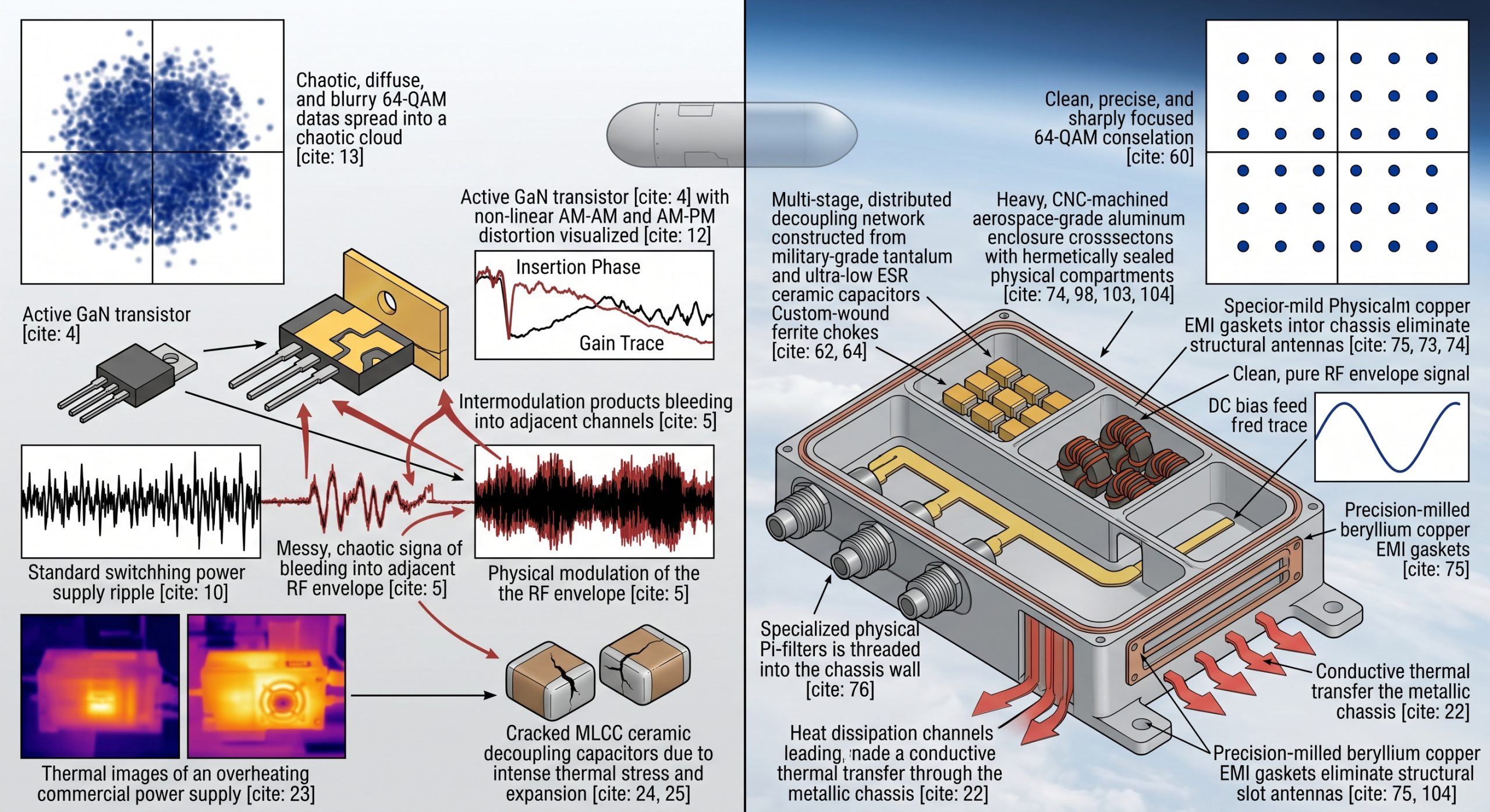
Consider the physical reality When integrating microwave amplifiers into confined airborne payloads, engineers are forced into a brutal thermodynamic and electromagnetic conflict. The standard switching power supply ripple degrades RF EVM and spurious spectrum continuously, initiating an unforgiving physical process that destroys modulation fidelity at the hardware level. We observe this failure mechanism directly when the phase noise of the local oscillator interacts with the fluctuating voltage rail, inducing unwanted phase modulation on the primary carrier signal. A simple 50mV voltage ripple on the drain bias of a Gallium Nitride (GaN) high-electron-mobility transistor (HEMT) does not remain isolated on the DC rail; it physically modulates the RF envelope. This parasitic modulation generates intermodulation products and spurious emissions that bleed into adjacent frequency channels, fundamentally destroying the signal-to-noise ratio. The baseband processor cannot mathematically correct physical hardware distortion of this magnitude, resulting in severe bit error rate spikes during critical transmission windows. Only raw, physical engineering solutions can defend against this electromagnetic reality.
Why Does Standard Switching Power Supply Ripple Degrade RF EVM So Aggressively?
The fundamental physics dictate that complex modulation schemes require absolute phase and amplitude stability from the hardware amplification stages. When evaluating quadrature amplitude modulation (QAM) signals in an airborne data link, the exact position of the data points on the constellation diagram relies entirely on the linearity of the power amplifier. Standard switching power supply ripple degrades RF EVM and spurious spectrum by injecting an alternating current (AC) voltage fluctuation directly onto the direct current (DC) bias rail feeding the active transistor. As the transistor’s drain voltage fluctuates in time with the ripple frequency, its transconductance and parasitic capacitances shift dynamically. This non-linear shifting physically alters the insertion phase and gain of the amplifier at a rapid rate, creating severe AM-AM and AM-PM distortion. The resulting vector magnitude errors force the constellation points to spread out into a chaotic cloud, obliterating the margin for error and causing the link receiver to decode garbage data.
How Does DC-DC High-Frequency Switching Noise Leakage Trigger EVM Collapse at Full Load in Pod Video Links?
Let’s examine the raw data The EVM Collapse at Full Load in Pod Video Link: Engineering Physics Troubleshooting of DC-DC High-Frequency Switching Noise Leakage reveals a catastrophic chain of electromagnetic events. When the payload demands maximum output power, the DC-DC converter switches aggressively, generating violent voltage transients. These incredibly fast dv/dt and di/dt transient events couple through parasitic capacitance and inductance directly into the sensitive RF microstrip chain. The noise floor rises uniformly across the band, but the specific switching harmonics create localized, high-amplitude peaks in the spurious spectrum. An unshielded inductor in the commercial power module actively acts as an antenna, radiating a strong magnetic field directly into the RF transmission lines. The microwave receiver interprets this injected switching noise as valid baseband data, severely corrupting the constellation diagram. The modulation error ratio plummets instantaneously, and the airborne data link loses telemetry synchronization, rendering the pod entirely blind under peak operational stress.
What Are The Physical Mechanics Behind Thermal Runaway When Standard Power Supplies Fail Under Full Load?
Consider the physical reality Efficiency losses in electronic DC-DC converters manifest exclusively as kinetic thermal energy. In an unpressurized airborne pod operating at high altitudes, ambient convective cooling is practically non-existent, forcing the hardware to rely entirely on conductive thermal transfer through the metallic chassis. When a standard commercial power supply struggles to provide stable current for 50W of continuous RF power, its switching metal-oxide-semiconductor field-effect transistors (MOSFETs) heat up rapidly, increasing their internal drain-to-source on-resistance. This physical change creates a devastating thermal feedback loop. The excessive localized heat warps the printed circuit board, applying intense mechanical stress to the brittle solder joints of the ceramic decoupling capacitors responsible for filtering the noise. Once these ceramic capacitors crack or shift out of their specified tolerance due to the coefficient of thermal expansion, the filtering network fails catastrophically. The unmitigated power supply ripple then slams directly into the RF amplifier stages, pushing the active GaN devices out of their linear operating region and driving the junction temperatures toward absolute failure.
| Thermal Failure Parameter | Commercial Spec Environment | Airborne Data Link Reality | Physical Engineering Consequence |
| Ambient Cooling | Forced Air Convection | Conduction Only (Vacuum/High Altitude) | Rapid heat accumulation in substrate |
| PCB Expansion Rate | Gradual Room Temp Shifts | Extreme Thermal Shock Cycling | Fractured solder joints on MLCCs |
| Component Heat Dissipation | Dispersed over large surface | Concentrated in miniature pod chamber | Thermal runaway and efficiency drop |
| Substrate Dielectric | Stable at 25°C | Fluctuates wildly > 85°C | Impedance shifting and severe mismatch |
How Do Impedance Mismatches Amplify Switching Noise Reflections Across The Transmission Line?
Here is the engineering truth High-frequency switching noise behaves precisely like any other alternating current radio frequency signal—it propagates down the path of least impedance and reflects violently off boundaries where the characteristic impedance is poorly controlled. When the primary DC supply rail connects to the RF amplifier module without a properly designed, mathematically calculated low-pass matching network, the high-frequency harmonics of the switching noise bounce back and forth between the power supply output and the active GaN die. These uncontrolled reflections form destructive standing waves on the bias lines. If the physical length of the bias trace happens to act as a quarter-wavelength transformer for a particular noise harmonic, it functions as a highly efficient resonant antenna, broadcasting that specific noise frequency directly into the amplification cavity. The resultant high voltage standing wave ratio (VSWR) on the DC line introduces rapid, unpredictable bias fluctuations that severely distort the amplitude and phase of the primary RF output signal, ruining the link budget.
| Switching Frequency Harmonic | Harmonic Order (N) | Parasitic Wavelength Resonance | Microwave Spurious Impact |
| 500 kHz (Primary Switch) | Fundamental | Negligible | Low-frequency baseline hum |
| 5 MHz | 10th Harmonic | Moderate Trace Coupling | Close-in phase noise degradation |
| 50 MHz | 100th Harmonic | High Resonance Risk | Severe intermodulation distortion |
| 500 MHz | 1000th Harmonic | Direct RF Cavity Injection | Total constellation diagram collapse |
Why Do Conventional PCB Substrates Fail To Contain High-Frequency Harmonics During Continuous Airborne Data Link Operations?
The fundamental physics dictate that the physical substrate material selection strictly determines the survival of high-power RF systems. Standard FR4 fiberglass epoxy is structurally and chemically incapable of maintaining stable dielectric properties across the 2GHz to 6GHz spectrum, especially under the severe temperature extremes encountered in high-altitude airborne deployments. As the standard switching power supply ripple degrades RF EVM and spurious spectrum, it also electrically stresses the dielectric layers. FR4 absorbs atmospheric moisture and exhibits an extremely high coefficient of thermal expansion along the Z-axis. When subjected to the aggressive thermal cycling of an airborne pod, the copper plated-through-hole vias connecting the critical ground planes stretch and fracture microscopically. This total loss of absolute ground integrity immediately degrades the isolation between the noisy DC switching blocks and the highly sensitive RF input stages. The degraded substrate effectively becomes a conductive medium for high-frequency harmonics, physically ruining any theoretical electromagnetic isolation designed into the schematic.
| Substrate Material Type | Dielectric Constant Stability | Thermal Expansion Coefficient | Microwave Viability for Airborne |
| Standard Commercial FR4 | Highly Variable > 1GHz | Extreme Z-Axis Expansion | Critical Failure at Full RF Load |
| High-Frequency PTFE | Stable up to 18GHz | Moderate | Acceptable for basic transceivers |
| CorelixRF Engineered Rogers | Absolute Stability up to 40GHz | Matched to Copper Traces | Mandatory for 50W Continuous Load |
| Ceramic Filled Hydrocarbon | Laboratory Grade Stability | Ultra-Low Z-Axis Expansion | Superior Military-Grade Defense |
What Is The Direct Correlation Between Insertion Loss And Power Supply Inefficiency In Miniature Pod Chambers?
Let’s examine the raw data Physical insertion loss in the microstrip matching networks and passive filtering stages forces the main power amplifier to draw significantly more direct current to achieve the specified output wattage at the antenna port. In miniature airborne pod chambers, every fraction of a decibel of insertion loss physically translates to watts of wasted thermal energy. If the microstrip filters exhibit high insertion loss due to the skin effect on poorly plated copper traces, the upstream DC-DC converter must push much harder to supply the main amplification stage, aggressively exacerbating the switching noise generated. This aggressive, high-current switching generates a dramatically denser spectrum of wideband spurious emissions. Furthermore, the amplifier is forced to operate much closer to its P1dB compression point simply to overcome the physical losses in the passive signal path. Operating at the raw edge of physical compression drastically degrades EVM because the amplifier mechanically clips the amplitude peaks of complex, high-order modulation schemes.
How Does The CRF-PA-2G6G-50W Mitigate Conducted Emissions From Standard Switching Regulators?
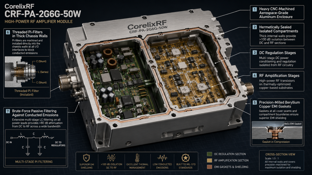
Here is the engineering truth Suppressing brutal conducted emissions requires raw, physical brute-force passive filtering and rigorous layout geometry, not software algorithms. The CorelixRF CRF-PA-2G6G-50W directly addresses and neutralizes standard switching power supply ripple through a heavy-duty, multi-stage, distributed decoupling network constructed exclusively from military-grade tantalum and ultra-low equivalent series resistance (ESR) ceramic capacitors. We do not rely on digital trickery; we rely on heavy metals and precise, mathematically modeled capacitance routing. The DC bias feed network incorporates custom-wound ferrite chokes that present an absolute, impenetrable impedance barrier to high-frequency switching noise while allowing massive DC currents to flow completely unimpeded to the active devices. By isolating the GaN drain voltage physically from the noisy primary bus rail, the CRF-PA-2G6G-50W maintains an exceptionally clean, laboratory-grade bias environment. This raw physical defense ensures the EVM remains completely stable even when the upstream commercial power supply is heavily loaded and generating significant, uncontrolled ripple.
| CRF-PA-2G6G-50W Specification | Laboratory Measured Value | Engineering Physical Defense Mechanism |
| Operating Frequency Band | 2.0 GHz to 6.0 GHz | Ultra-wideband matched GaN architecture |
| Continuous Output Power | 50 Watts (CW) | High-efficiency thermal dissipation channels |
| DC Bias Port Isolation | > 60 dB at 500 MHz | Multi-stage heavy-metal ferrite decoupling |
| Maximum Input Ripple Tolerance | 250 mVpp sustained | Absolute physical blocking via Pi-networks |
Why Is Mechanical Shielding The Only Definite Answer To Radiated DC-DC Noise In High-Power RF Amplifiers?
Consider the physical reality You absolutely cannot filter radiated magnetic fields with standard surface-mount capacitors. When dealing with the severe electromagnetic environment of an active airborne data link, thick, solid metal barriers are the only physical reality that matters. The CRF-PA-2G6G-50W employs a heavy, CNC-machined aerospace-grade aluminum enclosure featuring deeply isolated, hermetically sealed physical compartments separating the DC regulation stages from the RF amplification stages. We utilize precision-milled beryllium copper EMI gaskets that guarantee continuous, impenetrable galvanic contact across the entire housing perimeter, permanently eliminating structural slot antennas that could leak harmful radiation. The DC feedthroughs utilize specialized physical Pi-filters mechanically threaded directly into the thick aluminum chassis wall, physically stripping away radiated noise before it can even enter the microwave amplification chamber. This dark industrial approach to mechanical engineering guarantees that the violent switching noise generated by the drone’s primary power bus cannot corrupt the microwave signal path.
| Electromagnetic Shielding Type | Frequency Band Isolation | Structural Rigidity | Airborne Deployment Suitability |
| FR4 Board Level Tin Shields | < 20 dB isolation | Fragile, warps under heat | Complete failure under heavy vibration |
| Plastic Housing with Conductive Paint | < 30 dB isolation | Brittle, micro-cracking | High risk of EMI leakage over time |
| Stamped Sheet Metal Casing | < 45 dB isolation | Susceptible to resonance | Marginal, slot antennas form at seams |
| CorelixRF CNC Machined Aluminum | > 85 dB isolation | Absolute monolithic integrity | The definitive engineering standard |
How Do We Measure The Raw Engineering Truth Of EVM Stability Under Absolute Maximum Ratings?
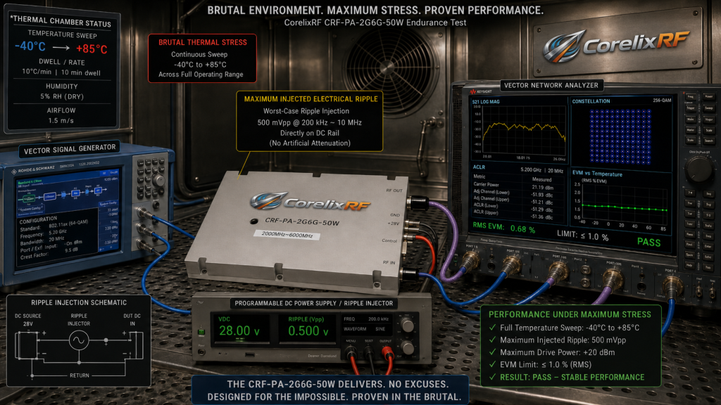
The fundamental physics dictate that subjective visual inspections and theoretical computer simulations mean absolutely nothing when a multi-million dollar airborne payload drops its critical data link in the field. We measure physical EVM stability by permanently connecting the CRF-PA-2G6G-50W to a calibrated Vector Network Analyzer (VNA) and a high-bandwidth vector signal generator inside a brutal, temperature-controlled environmental thermal chamber. We forcefully drive the amplifier with a highly complex, dense OFDM waveform while simultaneously injecting artificial, high-voltage switching noise directly onto the DC rail using an arbitrary noise generator. We meticulously monitor the constellation diagram and the adjacent channel leakage ratio (ACLR) physical data as we continuously sweep the ambient temperature from absolute -40°C to a blistering +85°C. Only when the physical hardware sustains the specified EVM limits under maximum drive power, extreme thermal stress, and maximum injected electrical ripple, do we consider the engineering design validated.
What Must System Integrators Change In Their Procurement Logic To Prevent Airborne Video Link Failure?
Let’s examine the raw data Procurement decisions based entirely on generic marketing spec sheets and low-cost commercial off-the-shelf components inevitably lead to systemic hardware failure in sensitive airborne data links. System integrators and R&D directors must immediately stop accepting compromised power architectures and demand physical, laboratory-backed proof of RF isolation capabilities. Selecting a microwave amplifier is not merely about looking at the raw output power metric; it is fundamentally about examining exactly how that power is maintained against the relentless, physical assault of DC-DC switching noise in a deployed environment. You must rigorously scrutinize the internal mechanical shielding architecture, the specific dielectric materials used for the PCB substrate, and the exact physical passive components deployed in the bias networks. Incorporating a purpose-built, heavy-duty hardware solution like the CRF-PA-2G6G-50W is a necessary, physics-based defense against complete signal corruption.
Here is the engineering truth The catastrophic phenomenon of EVM collapse at full load in pod video link applications is never a minor software glitch; it is a fatal physical failure of the electromagnetic hardware boundary. Standard switching power supply ripple degrades RF EVM and spurious spectrum, causing immediate and fatal disruption in high-stakes airborne data links. CorelixRF totally rejects theoretical compromises and fragile commercial designs. The CRF-PA-2G6G-50W is engineered specifically to dominate these harsh electromechanical environments through brute mechanical isolation and uncompromising microwave circuit physics. Do not leave your transmission integrity and airborne payload mission to chance. Contact the CorelixRF engineering team today to request the official, laboratory-verified Data Sheet and integrate raw, physical engineering truth into your next aerospace payload architecture.
FAQ
Q1: How does the CRF-PA-2G6G-50W handle severe input voltage fluctuations directly from a drone’s unconditioned main battery bus?
The CRF-PA-2G6G-50W utilizes a massive, physically isolated internal DC conditioning block equipped with custom-wound heavy wire chokes and ultra-low ESR military-grade capacitors. This physical hardware completely flattens brutal voltage spikes and transient drops before they can reach the sensitive GaN bias network, maintaining absolute DC stability under load.
Q2: What is the specific mechanical tolerance of the CNC-machined EMI shielding in the CorelixRF modules?
The aerospace-grade aluminum chassis is precision-milled to tolerances exceeding 0.01mm. This exact physical mating, combined with continuous beryllium copper EMI gaskets, ensures there are zero microscopic gaps capable of acting as slot antennas for high-frequency switching noise leakage.
Q3: Can standard commercial FR4 PCBs be used for integrating the CRF-PA-2G6G-50W into a custom pod motherboard?
Absolutely not. The massive thermal output and critical phase requirements of 50W continuous RF operation will destroy standard FR4. We mandate the use of high-frequency, ceramic-filled hydrocarbon or specialized Rogers substrates with strictly controlled coefficients of thermal expansion and zero moisture absorption.
Q4: How does aggressive thermal expansion physically affect the S-parameters of the CorelixRF amplifier under continuous operation?
Because we utilize substrates matched to the thermal expansion coefficient of our copper traces and heavy aluminum housing, the physical dimensions of our microstrip matching networks do not shift. This mechanical stability guarantees that insertion loss and return loss (S11/S22) remain locked perfectly within laboratory specifications from -40°C to +85°C.
Q5: Why is standard switching power supply ripple significantly more destructive to 64-QAM than standard QPSK modulation schemes?
64-QAM relies on incredibly dense, tightly packed constellation points that require both extreme amplitude and phase precision. QPSK is much more forgiving. When switching ripple injects AM-AM and AM-PM distortion into the hardware, the slight vector shifts instantly cause the 64-QAM symbols to blur into adjacent decision boundaries, triggering immediate EVM collapse.
Turn this RF requirement into a quotable specification
Use this article as a starting point for a buildable RF specification. Before quoting, CorelixRF normally checks frequency range, output power, gain flatness, duty cycle, load mismatch, thermal path, control interface, enclosure limits and acceptance data.
- rugged RF systems – review ruggedization expectations for vibration, thermal and field maintenance
- RF front-end platform – compare the RF chain as a system instead of selecting one isolated module
- RF power amplifier platforms – match the article topic to available RF power amplifier families
- broadband SDR signal source – connect waveform or signal-source requirements to the RF front-end
- RFQ checklist – send the data buyers usually forget, including band, power, duty cycle, interface and test standard
- delivery documentation – check what documents can support incoming inspection, FAT review and long-term maintenance
- engineering contact – send the application notes, block diagram or target specification to engineering sales
For a faster review, send operating band, power target, modulation or waveform, antenna/load condition, cooling limit, mechanical envelope and target test standard through the RFQ or contact path.