
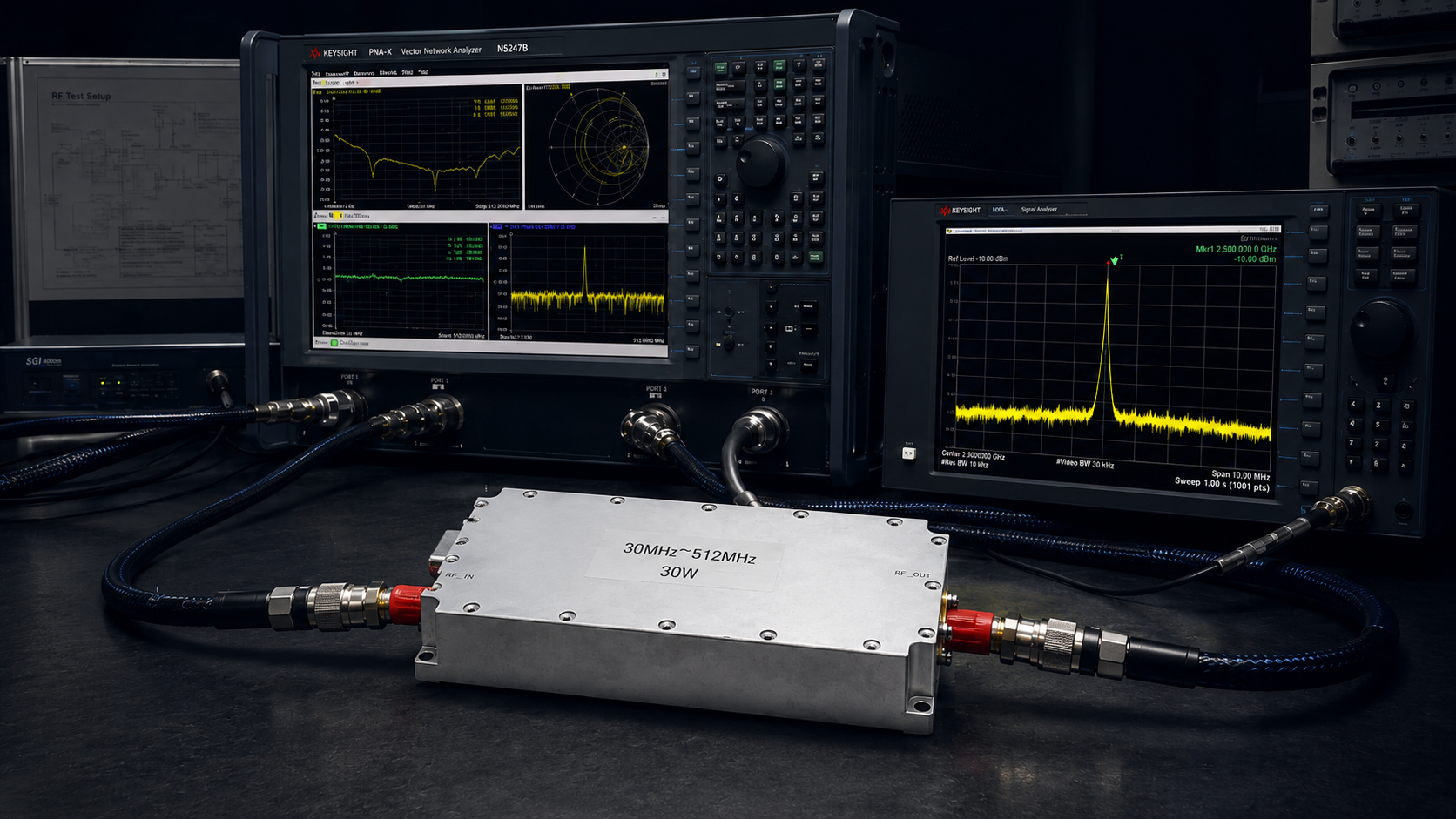
System integrators deploying uncrewed aerial vehicles and aerospace communication networks face a brutal operational reality. Telemetry links fail inexplicably, and airborne data link packet loss soaring becomes an unmanageable crisis during critical flight maneuvers. The truth about broadband spurious degradation caused by inferior buck modules is a hardware reality that many manufacturers ignore. Ordinary switching power supply ripple degrades RF EVM and spurious spectrum, flooding the receiver front-end with wideband noise. Consequently, the power amplifier rapidly degrades due to severe impedance mismatch and thermal overload, blinding the entire airborne communication node. The resulting catastrophic system failure leaves the command center without control over the payload. CorelixRF provides the definitive hardware defense mechanism against these physical failures. We engineer RF power amplifiers based on strict laboratory data and microwave electronics principles, rejecting generic marketing claims. The CRF-PA-30M512M-100W stands as our definitive solution, purpose-built to isolate, filter, and amplify complex waveforms in the most hostile airborne environments.
Why Do Inferior Buck Modules Cause Airborne Data Link Packet Loss Soaring?
System engineers routinely specify commercial-grade DC-DC buck converters to power RF payloads, unaware of the catastrophic consequences for the transmitter stage. Airborne data link packet loss soaring? The truth about broadband spurious degradation caused by inferior buck modules lies in the uncontrolled high-frequency switching transients generated by these power supplies. When a standard switching regulator operates at high altitudes, the lack of proper EMI shielding allows nanosecond rise-time current spikes to couple directly into the sensitive bias lines of the RF power amplifier. This conducted interference mixes with the primary RF carrier, generating wideband intermodulation distortion that completely saturates the receiver’s noise floor. Consequently, the dynamic range of the communication link collapses entirely. Consider the physical reality The switching frequency harmonics behave as parasitic modulation sources on the transistor’s drain voltage. When these harmonics interact with the non-linear transfer function of the amplifier, they spawn a comb of spurious emissions across the entire operating band. The digital signal processor at the receiving end can no longer differentiate between valid constellation symbols and random noise, resulting in immediate synchronization failure and soaring packet drop rates that render the telemetry system permanently unresponsive during flight.
How Does Ordinary Switching Power Supply Ripple Degrade RF EVM and Spurious Spectrum?
The relationship between DC power quality and complex digital modulation fidelity is an absolute law of microwave electronics. Ordinary switching power supply ripple degrades RF EVM and spurious spectrum by superimposing low-frequency voltage variations onto the amplitude and phase of the amplified radio frequency signal. A standard commercial buck module might present 100 millivolts of peak-to-peak ripple, which acts as direct amplitude modulation on the carrier wave. In 64-QAM or 256-QAM OFDM systems, this unintended amplitude fluctuation randomly shifts the transmitted symbols away from their ideal constellation points. The error vector magnitude abruptly spikes from a nominal 1.5% to an unacceptable 12%, immediately violating the protocol threshold and forcing the modem to drop data frames continually. Let’s examine the raw data Laboratory spectrum analyzer measurements confirm that unfiltered DC ripple generates distinct sidebands spaced exactly at the switching frequency intervals from the main carrier. These sidebands violate the adjacent channel leakage ratio specifications, causing the transmitter to actively jam nearby receivers on the same aerial platform. The resulting broadband spurious spectrum directly correlates to the failure of the forward error correction algorithms, halting all data transmission.
| Parameter | Commercial Buck Module | CorelixRF Clean Power | Impact on System |
| DC Ripple | 100mV peak-to-peak | < 5mV peak-to-peak | EVM spike, packet loss |
| Phase Noise | -80 dBc/Hz @ 10kHz | -110 dBc/Hz @ 10kHz | Constellation smearing |
| Spurious Output | -40 dBc | -65 dBc | Receiver blinding |
What Happens to Amplifiers Under Extreme Thermal Expansion and Contraction?
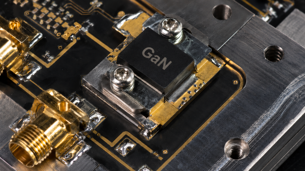
High-altitude environments subject RF hardware to vicious temperature gradients, often swinging from -55°C at high atmosphere to +85°C internal chassis temperatures within minutes. This extreme thermal expansion and contraction physically tears inferior hardware apart at the microscopic level. The coefficient of thermal expansion mismatch between the active gallium nitride dies and the surrounding copper heat spreaders introduces massive mechanical shear stress on the eutectic solder joints. Over repeated flight cycles, micro-cracks propagate through the substrate, drastically increasing the thermal resistance of the junction. As heat fails to dissipate, the active device temperature exceeds maximum ratings, causing the RF output power to slump dramatically and accelerating device failure. Furthermore, the mechanical deformation of the printed circuit board alters the physical dimensions of the microstrip matching networks. Because the wavelength of the RF signal is directly tied to the physical geometry of the copper traces, any warping shifts the resonant frequency of the matching circuit. This physical deformation creates an immediate impedance mismatch between the amplifier stages, resulting in reflected power that compounds the thermal load and further degrades the amplifier’s insertion loss and linearity.
Why Are Commercial Power Supplies Insufficient for Airborne Data Links?
Off-the-shelf commercial power modules are engineered for benign, ground-based laboratory conditions where weight, vibration, and atmospheric pressure are negligible variables. They utilize low-cost electrolytic capacitors that dry out or physically burst in unpressurized high-altitude environments, immediately removing all low-frequency decoupling from the DC bias lines. Without these capacitors, the transient current demands of the pulsed RF power amplifier cannot be met, causing severe voltage droop during peak transmission periods. This voltage droop distorts the leading edge of the RF pulse, ruining the spectral mask and generating out-of-band emissions that interfere with critical navigation equipment. The fundamental physics dictate Commercial modules lack the hermetic sealing and potting required to prevent high-voltage arcing in thin air. At high altitudes, the dielectric strength of air decreases significantly, allowing high-voltage nodes within the switching power supply to arc across the printed circuit board. These micro-arcs inject massive broadband electromagnetic interference directly into the RF cavity. Only a heavily ruggedized power conditioning network, specifically designed for aerospace microwave applications, can survive these harsh operational realities without corrupting the signal chain.
| Environmental Stress | Standard Plastic Packaging | Hermetic Aerospace Shielding | Failure Consequence |
| Altitude Depressurization | Electrolytic capacitor venting | Solid tantalum stability | Total bias loss |
| -55°C to +85°C Cycle | Solder micro-fractures | Eutectic gold-tin bonding | Increased thermal resistance |
| Extreme Humidity | Trace oxidation | Gold-plated microstrips | Impedance drift |
How Does the CRF-PA-30M512M-100W Suppress Broadband Spurious Emissions?
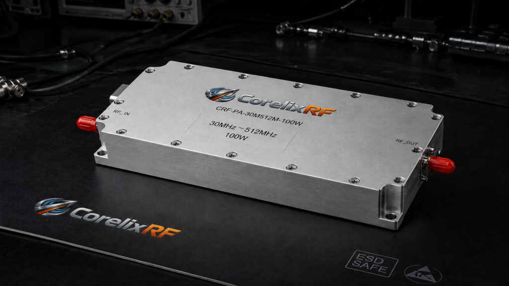
The CorelixRF engineering team recognized that isolating the RF chain from the power supply is the only method to guarantee signal integrity. The CRF-PA-30M512M-100W employs a multi-stage, military-grade internal power conditioning architecture to ruthlessly suppress broadband spurious emissions. We integrate heavy LC Pi-filter networks directly at the DC input terminal, followed by ultra-low noise, high-current low-dropout linear regulators that provide the final bias voltage to the transistor drains. This architecture actively strips away the high-frequency switching hash and low-frequency ripple before it can ever reach the active amplification stages. Here is the engineering truth By completely isolating the RF transistors from the noisy primary bus voltage, the CRF-PA-30M512M-100W maintains an absolute spectral purity that commercial amplifiers simply cannot achieve. Our vector network analyzer and spectrum analyzer characterization data demonstrate a spurious emission rejection ratio exceeding 65 dBc across the entire 30 MHz to 512 MHz operating band. This pristine spectral mask guarantees that the airborne data link maintains maximum receiver sensitivity, completely eliminating the hardware-induced packet loss that plagues inferior designs.
| Specification | Market Average | CRF-PA-30M512M-100W | Engineering Truth Validation |
| Frequency Band | 30-512 MHz (with gaps) | 30-512 MHz (continuous) | VNA S21 measurement |
| Harmonic Rejection | -15 dBc | -25 dBc | Raw spectrum analyzer data |
| Spurious Rejection | -45 dBc | > -65 dBc | Conducted emissions test |
What Role Does Impedance Mismatch Play in Catastrophic System Failure?
In an airborne deployment, the antenna subsystem is constantly subjected to structural vibration, ice accumulation, and aerodynamic stress, all of which alter its characteristic impedance in real-time. When the antenna impedance deviates from the nominal 50 ohms, an impedance mismatch occurs, causing a significant portion of the transmitted RF energy to reflect back into the power amplifier. This reflected energy establishes standing waves along the transmission line, resulting in massive voltage nodes that can instantly exceed the breakdown voltage of the final stage output transistors, destroying the semiconductor junctions permanently. This catastrophic failure mode is accelerated by the lack of protective circulation circuitry in cheap hardware. The reflected power turns into raw thermal energy precisely at the output matching network, rapidly melting the solder joints and burning the FR4 PCB material. The resulting carbonized circuit board acts as a dead short to ground, guaranteeing that the entire telemetry module fails instantly. A professionally engineered system must account for absolute worst-case voltage standing wave ratio conditions without relying on software-based power foldback algorithms that react too slowly to prevent transistor burnout.
How Can System Integrators Verify Actual Laboratory Data Versus Marketing Claims?
The B2B RF component market is saturated with exaggerated output power specifications and theoretical performance charts that have never been validated under continuous wave operation. System integrators must demand strict, verifiable laboratory data rather than relying on computer-generated imagery and empty marketing narratives. Analyzing the raw s-parameters, small-signal gain flatness, and specifically the insertion loss of the output protective isolator provides the only factual baseline for evaluating an amplifier’s true capability. If a manufacturer cannot provide physical thermal imaging data or vector network analyzer screenshots of their module under full load, their claims are fundamentally invalid. System engineers must request the exact test bench configuration, including the specific signal generators, continuous wave power meters, and directional couplers used to qualify the hardware. Evaluating the two-tone third-order intercept point under varying temperature conditions will immediately reveal if the module relies on excessive digital pre-distortion to mask poor fundamental linearity. CorelixRF strictly publishes baseline physical measurements, ensuring that our clients understand the exact mechanical and electrical boundaries of the hardware they are integrating into their multi-million-dollar aerospace platforms.
| Marketing Claim | Physical Reality Check | Mandatory Verification Instrument |
| “Perfect Linearity” | Check two-tone intermodulation | Spectrum Analyzer (IMD3 test) |
| “Indestructible” | Request VSWR tolerance limit | Directional Coupler + Dummy Load |
| “High Efficiency” | Measure input DC vs RF output | Calibrated Power Meter + Ammeter |
Where Does the Mechanical Tolerancing Factor Into High-Altitude RF Performance?
Microwave electronics are fundamentally bound by mechanical precision, where physical dimensions directly dictate electromagnetic behavior. The mechanical tolerancing of the amplifier’s housing determines the exact volume of the RF cavity, which in turn dictates the cutoff frequency and the potential for parasitic cavity resonance. If the CNC machining tolerances are loose, the internal compartment can inadvertently act as a microwave waveguide, allowing the amplifier to oscillate wildly at unintended frequencies. This self-oscillation destroys the targeted signal and severely degrades the overall system error vector magnitude. Furthermore, loose mechanical tolerances compromise the electromagnetic interference shielding effectiveness of the entire chassis. Microscopic gaps between the lid and the housing allow stray RF energy from the internal matching networks to leak out and contaminate the primary flight computer, while simultaneously allowing external radar pulses to penetrate the amplifier’s bias circuitry. Precision machining, strict surface flatness requirements, and the correct application of conductive EMI gaskets are non-negotiable physical realities required to maintain absolute isolation between the high-power RF output and the sensitive telemetry sensors onboard the aircraft.
What Is the Physical Defense Mechanism Inside the CRF-PA-30M512M-100W?
The physical defense mechanism engineered into the CRF-PA-30M512M-100W relies on brute-force hardware isolation and superior material science. The chassis is CNC-machined from a solid block of aerospace-grade aluminum, designed to eliminate any parasitic cavity resonance while maximizing the thermal transfer area. We utilize advanced Teflon insulators and gold-plated microstrip traces to minimize insertion loss and prevent long-term oxidation in high-humidity environments. Every internal RF connection is manually inspected for absolute solder joint integrity, ensuring that the module survives the extreme shock and vibration profiles specified by military aerospace standards. To defend against impedance mismatch and infinite VSWR conditions, the CRF-PA-30M512M-100W integrates a heavy-duty, high-power output isolator directly into the signal chain. This purely magnetic component acts as a one-way valve for the RF energy, routing any reflected power from a damaged antenna directly into a massive beryllium oxide dummy load instead of back into the delicate transistor junctions. This physical hardware defense guarantees that the amplifier will continue to operate at maximum forward power even if the external antenna is completely sheared off during flight operations.
| Defense Mechanism | Component Used | Operational Function |
| Reflected Power Block | High-Power Ferrite Isolator | Protects GaN transistor junction |
| Thermal Dissipation | Beryllium Oxide Resistor | Converts standing waves to heat safely |
| Ground Isolation | Heavy-Duty CNC Chassis | Prevents parasitic cavity resonance |
Why Must R&D Directors Prioritize Engineering Truth Over Cost Optimization?
The decision to integrate unverified, commercial-grade RF components into mission-critical aerospace platforms is a calculated risk that invariably results in catastrophic financial and operational losses. Prioritizing initial cost optimization over engineering truth leads to a cascade of hardware failures in the field. When a cheap buck converter compromises the airborne data link, the resulting loss of telemetry can easily result in the total loss of a multi-million-dollar uncrewed aerial vehicle. The expense of a single dropped mission far outweighs the fractional savings gained by purchasing sub-standard amplification modules. R&D directors must acknowledge that physical limitations cannot be circumvented by clever software engineering or digital signal processing. If the fundamental hardware generates excessive intermodulation distortion, cannot survive thermal cycling, and lacks hardware-level VSWR protection, the communication link will fail regardless of the error correction protocols applied. CorelixRF stands on the side of rigorous laboratory testing, physical material science, and absolute technical transparency. We build our hardware to solve the most brutal physical problems encountered in modern aerospace communications.
Conclusion
The physical reality of high-altitude telemetry requires uncompromised hardware design. Airborne data link packet loss is not an unsolvable mystery; it is a direct result of failing to control basic power supply parameters and thermal dynamics. By implementing strict filtering and heavy-duty mechanical isolation, CorelixRF ensures absolute signal integrity. System integrators requiring absolute reliability must transition from consumer-grade illusions to verifiable microwave engineering. Contact the CorelixRF engineering team today to secure the official technical data sheet for the CRF-PA-30M512M-100W and review the raw laboratory test results.
Frequently Asked Questions
Q1: How does the CRF-PA-30M512M-100W handle a completely disconnected antenna during operation?
A1: The CRF-PA-30M512M-100W utilizes a high-power internal isolator that routes 100% of the reflected RF energy into an internal dummy load. This physical defense mechanism prevents the final stage transistors from experiencing over-voltage conditions, guaranteeing survival under infinite VSWR scenarios.
Q2: Can we power this amplifier directly from a standard 28V aircraft bus?
A2: Yes, the amplifier features extensive internal power conditioning designed to accept raw, noisy DC bus voltage. Our heavy LC filtering and multi-stage LDO architecture strip away the bus ripple, preventing any degradation of the RF EVM.
Q3: What is the maximum operating temperature for the CRF-PA-30M512M-100W?
A3: The baseplate is rated for continuous operation up to +85°C. System integrators must ensure adequate thermal bonding between the module baseplate and the aircraft chassis to maintain safe junction temperatures within the GaN devices.
Q4: Why does CorelixRF publish specific laboratory spectrum analyzer screenshots?
A4: We rely on engineering truth. Providing raw, unedited spectrum analyzer and vector network analyzer data proves our hardware’s linearity and spurious emission rejection, allowing engineers to verify our specifications against fundamental physics.
Q5: Does this module require external digital pre-distortion to achieve its EVM targets?
A5: No. The CRF-PA-30M512M-100W is engineered with exceptional raw hardware linearity. While DPD can be applied at the modem level for further refinement, our module meets strict adjacent channel leakage ratio requirements through fundamental microwave design.
Turn this RF requirement into a quotable specification
Use this article as a starting point for a buildable RF specification. Before quoting, CorelixRF normally checks frequency range, output power, gain flatness, duty cycle, load mismatch, thermal path, control interface, enclosure limits and acceptance data.
- rugged RF systems – review ruggedization expectations for vibration, thermal and field maintenance
- RF front-end platform – compare the RF chain as a system instead of selecting one isolated module
- RF power amplifier platforms – match the article topic to available RF power amplifier families
- broadband SDR signal source – connect waveform or signal-source requirements to the RF front-end
- RFQ checklist – send the data buyers usually forget, including band, power, duty cycle, interface and test standard
- delivery documentation – check what documents can support incoming inspection, FAT review and long-term maintenance
- engineering contact – send the application notes, block diagram or target specification to engineering sales
For a faster review, send operating band, power target, modulation or waveform, antenna/load condition, cooling limit, mechanical envelope and target test standard through the RFQ or contact path.