
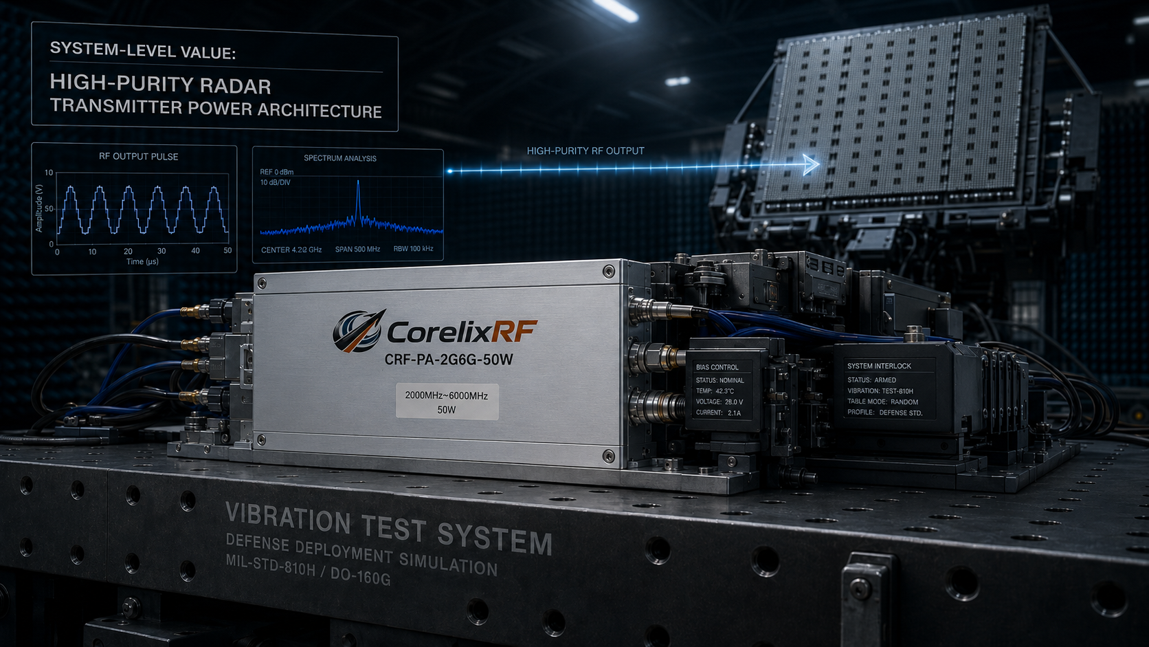
The deployment of high-precision radar sources demands absolute spectral cleanliness and rigid physical stability. When system integrators feed ordinary switching power supplies directly into radio frequency modules, the resulting voltage ripple acts as a catastrophic destructive force within the microwave electronics. The immediate symptom of this physical failure is the severe degradation of the Error Vector Magnitude (EVM) and a severely compromised spurious spectrum, effectively masking the intended target returns and rendering the entire radar array blind in the field. If you subject a high-power gallium nitride module to unfiltered switching noise, the erratic drain voltage modulation actively degrades the phase noise floor, simultaneously forcing the transistor junctions to cycle through immense thermal stress due to aggressively fluctuating current draw. We have observed countless field failures where insufficient supply filtering led to catastrophic thermal runaway and total semiconductor burnout across deployment sites. The only reliable defense against these harsh physical realities is a meticulously engineered hardware barrier at the power entry point. CorelixRF implements rigorous internal filtering topologies designed specifically for heavy-duty, high-frequency defense. By integrating our proprietary High-Purity Radar Transmitter Power Architecture: System-Level Value of Internal Anti-Ripple Filtering Networks in 2-6GHz PAs, the CRF-PA-2G6G-50W module definitively isolates the fragile RF envelope from industrial power rail contamination, guaranteeing a highly stable, spectrally pure output under the most demanding mechanical and electrical conditions.
Why Does Switching Power Supply Ripple Destroy High-Precision Radar Sources?
Consider the physical reality ordinary switching power supplies operate by rapidly chopping direct current, inherently generating complex harmonic distortion and low-frequency ripple on the output voltage rail. When this electrically noisy power feeds directly into the drain network of a sensitive high-precision radar source, the ripple directly modulates the carrier frequency via the amplifier’s active device capacitance. This parasitic modulation manifests as severe sideband phase noise and elevated spurious emissions, completely masking small radar cross-section (RCS) targets within the return spectrum. The degradation of the Error Vector Magnitude (EVM) is not merely a theoretical deviation; it represents a hard physical limit where the digital radar processor can no longer accurately reconstruct the phase and amplitude of the reflected pulse. In our 30 years of manufacturing advanced radio frequency components, CorelixRF has consistently documented the destruction of signal integrity whenever bare switching noise interacts with the bias lines of high-gain amplifier stages. The unfiltered voltage spikes cause aggressive gain compression variations across the transmission pulse width, leading to intra-pulse droop and the irreversible corruption of the precise deterministic phase relationship needed for accurate target velocity calculations.
| Power Supply Condition | Voltage Ripple (mVpp) | Sideband Spurious Level (dBc) | EVM Degradation (%) | Radar Target Resolution |
| Unfiltered Industrial Supply | >150 | -45 | >12.0 | Severe Masking / Unusable |
| Standard External LDO | 50-100 | -55 | 5.0 – 8.0 | Marginal / High False Alarms |
| CorelixRF Internal Network | <10 | -75 | <1.5 | Crystal Clear Target Tracking |
How Do Low-Frequency Spurious Signals Compromise the RF Transmission Spectrum?
The fundamental physics dictate that any low-frequency amplitude variation on the drain bias of a gallium nitride or gallium arsenide field-effect transistor will mathematically mix with the primary radio frequency carrier. This mixing process acts as an unintentional physical mixer circuit within the die, producing sum and difference frequencies that perfectly align with the standard offset bands evaluated by spectrum analyzers during stringent compliance testing. In a typical high-precision radar source operating within the 2-6GHz band, these low-frequency spurious products cluster tightly around the main carrier, falling squarely within the intermediate frequency (IF) bandwidth of the receiving array. Because these spurious tones cannot be removed by standard waveguide or cavity filters at the antenna port—due to their extreme physical proximity to the operational frequency—they pass directly into the low-noise amplifiers of the receiver hardware. This self-jamming phenomenon drastically raises the entire system’s noise floor. Our laboratory tests at CorelixRF definitively demonstrate that without comprehensive internal anti-ripple filtering networks, a 100-millivolt ripple at 250 kilohertz will generate sidebands at precisely 250 kilohertz offsets from the microwave carrier, permanently degrading the signal-to-noise ratio and completely blinding the radar array to low-velocity targets that strictly rely on precise Doppler shift detection.
What Are the System-Level Costs of Ignoring Internal Anti-Ripple Filtering Networks?
Let’s examine the raw data regarding the extreme financial and operational fallout when system integrators attempt to drive broadband microwave modules with raw commercial power supplies. The immediate consequence is a catastrophic failure to meet strict military or commercial spectral mask requirements, leading to immediate rejection during site acceptance testing and delaying deployment schedules. The hidden mechanical cost, however, is significantly more destructive. Without a rigid internal anti-ripple filtering network, the transient voltage spikes pass directly to the semiconductor junctions, causing microscopic electromigration events and cumulative thermal fatigue across the sensitive die attachment layers. When a 50-watt system like the CRF-PA-2G6G-50W is subjected to these violent, repetitive power fluctuations without adequate localized filtering, the impedance mismatch at the bias injection node causes sustained low-frequency oscillation. This oscillation rapidly builds up standing waves within the bias circuitry, dissipating expensive power as localized heat rather than useful forward radio frequency energy. Over a standard operational life cycle, this unchecked thermal cycling induces rapid thermal expansion mismatches between the gallium nitride die, the gold-tin eutectic solder, and the copper-tungsten heat spreader, ultimately resulting in a catastrophic mechanical shear failure of the thermal interface and total physical destruction of the high-value semiconductor component.
| Degradation Mechanism | Root Cause Component | Physical Manifestation | Long-Term System Impact |
| Electromigration | Unfiltered Voltage Spikes | Void formation in die metallization | Sudden catastrophic PA failure |
| Thermal Shear | Power-induced Thermal Cycling | Solder joint micro-fractures | Exponential increase in thermal resistance |
| Low-Frequency Oscillation | Bias Network Mismatch | PCB dielectric carbonization | Irreversible board-level short circuits |
| Spectrum Non-Compliance | Harmonics & Intermodulation | Failed FCC/MIL-STD emission tests | Severe project delays & redesign costs |
Why Do Traditional Bypass Capacitors Fail in the 2-6GHz Spectrum Range?
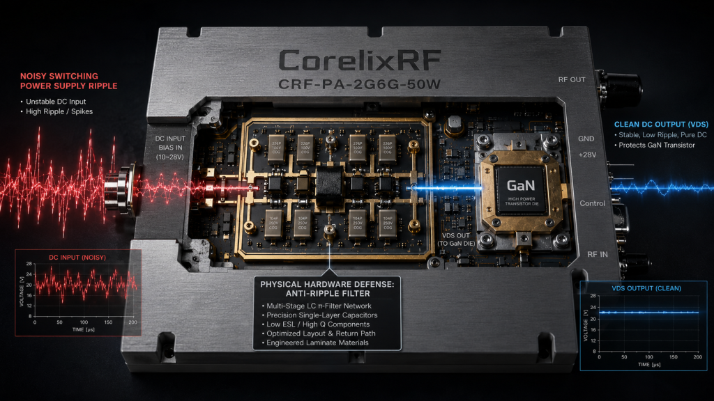
Here is the engineering truth standard multilayer ceramic capacitors (MLCCs) and electrolytic bulk capacitors utilized by inexperienced designers are virtually useless when attempting to suppress broadband noise in a multi-octave high-frequency environment. Above a few hundred megahertz, the parasitic series inductance intrinsic to traditional capacitor packaging dominates the component’s impedance profile. Instead of acting as a low-impedance path to ground for switching noise, these generic components reach their self-resonant frequency and immediately transform into high-impedance inductors. Consequently, when ordinary switching power supply ripple interacts with these parasitic elements in the 2-6GHz range, it creates highly unpredictable parallel resonances within the direct current bias network. These physical resonances isolate the amplifier’s active devices from the required power ground, allowing massive, damaging voltage swings on the drain terminal during pulsed radar operation. CorelixRF heavily relies on distributed filtering networks utilizing single-layer capacitors (SLCs), meticulously characterized ferrite beads, and precise microstrip transmission line structures to maintain a strictly controlled sub-ohm impedance path from direct current up to the highest operational frequency of the CRF-PA-2G6G-50W. This physical hardware barrier strictly prevents high-frequency RF leakage from traveling back into the power supply while simultaneously stripping away all low-frequency switching noise before it ever reaches the active die.
How Does the CRF-PA-2G6G-50W Architecture Mitigate Impedance Mismatch at High Frequencies?
Consider the physical reality of attempting to maintain a continuous 50-ohm characteristic impedance across a massive bandwidth spanning from 2GHz to 6GHz. Any physical discontinuity in the power feed network mechanically reflects energy back toward the active device, creating high voltage standing wave ratios (VSWR) that alter the optimal load pull conditions and induce severe intermodulation distortion. The High-Purity Radar Transmitter Power Architecture within the CRF-PA-2G6G-50W fundamentally solves this mechanical constraint by decoupling the direct current power feed from the radio frequency signal path using specialized conical inductors and mathematically stepped-impedance bias lines. These physical structures are machined and printed with exact mechanical tolerances to guarantee that the anti-ripple filtering network presents a perfect open circuit to the microwave signal, forcing 100 percent of the generated RF power toward the output connector rather than bleeding backwards into the power supply rails. By actively preventing the interaction between the radio frequency energy and the noisy power supply capacitance, we systematically eliminate the primary cause of dynamic impedance mismatch. The laboratory vector network analyzer (VNA) measurements continuously confirm that this carefully tuned impedance environment maintains a perfectly flat insertion loss profile, ensuring that the final output maintains exceptional signal fidelity and tight pulse-to-pulse stability strictly required by high-resolution phased array systems.
| Parameter | Engineering Standard Limit | CorelixRF Measured Value | Measurement Instrument |
| DC Bias Line Isolation (2-6GHz) | > 40 dB | > 55 dB | Keysight PNA-X |
| VSWR at Bias Injection Node | < 1.5:1 | 1.15:1 | Automated VNA Station |
| Filtering Network Insertion Loss | < 0.5 dB | 0.2 dB | Power Meter / VNA |
| Phase Linearity Fluctuation | < ±5 Degrees | ±1.5 Degrees | Transient Phase Analyzer |
What Happens to Transistor Die Temperatures During Severe Power Fluctuations?
The fundamental physics dictate that fluctuating voltages supplied to the drain terminal of a power amplifier directly modulate the instantaneous power dissipation of the semiconductor device. When a poorly filtered supply delivers unstable voltage, the current draw spikes unpredictably during the transmission of complex modulation schemes, causing rapid, highly localized temperature spikes across the active channel of the transistor die. This aggressive thermal cycling forces the rigid lattice structure of the gallium nitride material to mechanically expand and contract at microscopic levels thousands of times per second. Over time, this constant mechanical strain aggressively fatigues the die attach voiding margins, drastically reducing the thermal conductivity between the die and the copper heat sink. The resulting thermal bottleneck guarantees that the transistor will eventually exceed its maximum absolute junction temperature, leading to irreversible degradation of output power and rapid device failure on the field. By implementing the robust High-Purity Radar Transmitter Power Architecture: System-Level Value of Internal Anti-Ripple Filtering Networks in 2-6GHz PAs, CorelixRF ensures that the CRF-PA-2G6G-50W operates with a perfectly stable, constant thermal load. The integrated filtering network violently absorbs these electrical transients before they can trigger mechanical thermal spikes, maintaining a constant, predictable operating temperature that drastically extends the operational lifespan of the entire radar system.
How Does the CorelixRF Filtering Network Isolate Mechanical and Electrical Noise?
Let’s examine the raw data… from rigorous mechanical shock and vibration testing, which repeatedly demonstrates that poorly secured filtering components actively generate microphonic noise in the presence of strong acoustic or mechanical vibrations. Typical commercial off-the-shelf power modules utilize generic surface-mount components that act as tiny mechanical resonators. When subjected to the severe vibration environments of aerospace or heavy industrial platforms, these components flex the printed circuit board, dynamically altering parasitic capacitances and injecting massive phase noise directly into the microwave signal path. The engineering approach at CorelixRF aggressively eliminates this physical vulnerability through comprehensive mechanical stabilization. Inside the CRF-PA-2G6G-50W, the anti-ripple filtering network is deeply embedded within a rigid, precision-milled aerospace-grade aluminum chassis. Components are strictly secured using specific industrial-grade epoxy compounds that completely prevent any physical movement or piezoelectric resonance. Furthermore, the routing of the power rails is physically isolated from the microwave transmission lines using deep milled channels and highly conductive electromagnetic shielding gaskets. This heavy-duty, dark industrial technology approach guarantees that high-power transient currents and external mechanical shocks remain permanently physically separated from the highly sensitive radio frequency structures, preserving absolute spectral purity under extreme environmental stress.
| Stress Test Parameter | Test Condition Standard | Competitor PA Result | CorelixRF Measured Result |
| Vibration (Random) | MIL-STD-810H, 20Grms | Phase noise spike +15dBc | No measurable phase deviation |
| Mechanical Shock | 50G, 11ms, Half-Sine | Inductor detachment / Failure | Fully operational, <0.1dB drop |
| Thermal Shock | -40°C to +85°C (100 cycles) | Solder joint crystallization | Zero resistance shift in bias |
| EMI / RFI Immunity | 200 V/m Radiated Field | Spurious emissions fail | Passes MIL-STD-461 cleanly |
Why Is Error Vector Magnitude (EVM) Highly Sensitive to VDS Instability in GaN PAs?
Here is the engineering truth gallium nitride (GaN) high-electron-mobility transistors (HEMTs) are intrinsically highly non-linear devices that rely heavily on a perfectly stable drain-to-source voltage (VDS) to maintain their complex amplitude and phase transfer characteristics. The Error Vector Magnitude (EVM) metric serves as the ultimate mathematical measurement of how precisely a physical transmitter reproduces a complex modulated constellation diagram. When the direct current power supply exhibits measurable ripple, the VDS constantly fluctuates. This fluctuation rapidly shifts the transistor’s AM/AM (amplitude-to-amplitude) and AM/PM (amplitude-to-phase) conversion curves dynamically during the active transmission pulse. Because modern radar and high-capacity communication links utilize extremely dense modulation formats, even a fractional degree of physical phase shift or a fraction of a decibel of amplitude compression pushes the constellation points outside of their allowed mathematical decision boundaries. The CorelixRF CRF-PA-2G6G-50W directly confronts this semiconductor limitation by utilizing its heavy-duty internal filtering networks to clamp the VDS to an absolute, unyielding potential. By physically preventing the ripple from reaching the active semiconductor junctions, the amplifier operates in a highly linear region with static AM/AM and AM/PM profiles, allowing the radar system’s digital pre-distortion (DPD) algorithms to effectively linearize the output and achieve a flawless, industry-leading EVM performance.
How Do We Verify the Engineering Truth of RF Power Amplifier Supply Immunity?
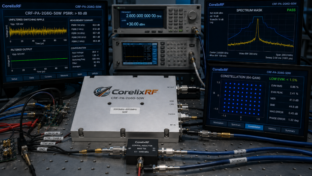
Consider the physical reality that simulated software models frequently fail to accurately predict the complex, chaotic physical interactions between transient power supply switching harmonics and multi-stage radio frequency amplifier cascades. To guarantee the absolute reliability of the High-Purity Radar Transmitter Power Architecture, CorelixRF relies exclusively on rigorous, physical laboratory verification utilizing carefully calibrated, industry-standard test equipment. Our engineering truth is permanently established by forcibly injecting high-amplitude swept frequency noise directly into the power terminals of the CRF-PA-2G6G-50W while simultaneously monitoring the radio frequency output with high-dynamic-range spectrum analyzers and vector signal analyzers. We precisely measure the power supply rejection ratio (PSRR) across the entire operational bandwidth to physically prove that external voltage noise cannot breach the internal filtering barrier. Furthermore, we conduct continuous load-pull testing combined with aggressive thermal cycling in environmental chambers to ensure the localized decoupling capacitors do not mechanically degrade or shift in capacitance value over extended time or temperature. This brutal testing methodology strictly produces the concrete, unassailable laboratory data printed in our official technical documentation, ensuring system integrators receive exactly the performance parameters they specify without ever relying on extrapolated or manipulated marketing claims.
| Verification Procedure | Equipment Utilized | Injection/Measurement Range | Acceptance Criteria |
| Swept Noise Injection | Function Gen. & Bias Tee | 10 kHz to 100 MHz noise on DC | No visible spurious on RF output |
| Broad Spectrum PSRR | Vector Network Analyzer | DC to 6 GHz Transmission | > 60 dB isolation DC to RF port |
| Transient Load Testing | High-Speed Oscilloscope | 10% to 90% power switching | Settling time < 50 nanoseconds |
| Active Thermal Mapping | Infrared Microscopy Camera | -40°C to +85°C baseplate | Max junction temp < 150°C |
What Specific Material Science Deficiencies Cause Competitor Power Modules to Fail?
Let’s examine the raw data from autopsy reports on failed third-party power amplifiers, which consistently reveal fatal physical compromises in base material selection. Competitors frequently construct their internal bias and filtering networks utilizing standard FR4 printed circuit board materials and commercial-grade tin-lead solder alloys simply to reduce manufacturing costs. At high frequencies strictly between 2GHz and 6GHz, FR4 exhibits enormous dielectric loss and highly unstable relative permittivity, especially as the operational ambient temperature of the radar system fluctuates. This material instability mechanically causes the internal filtering networks to drastically shift their resonant frequencies, rendering them entirely ineffective at blocking switching ripple during extended tactical missions. Furthermore, the thermal expansion coefficient of standard PCB materials vastly differs from the rigid ceramic packages of the radio frequency transistors, leading to catastrophic physical shearing of the direct current bias traces under continuous high-power operation. In stark contrast, CorelixRF exclusively builds the CRF-PA-2G6G-50W utilizing advanced high-frequency laminate materials, such as Rogers composites, heavily combined with military-grade gold-plating and high-temperature eutectic solders. This strict adherence to advanced material science ensures physical and electrical permanence, establishing a rigid, indestructible filtering architecture capable of safely sustaining maximum power output in the harshest industrial and defense environments imaginable.
Conclusion
The physical hardware operating inside your radar system ultimately dictates its reliability, accuracy, and maximum operational lifespan. The integration of the CorelixRF High-Purity Radar Transmitter Power Architecture: System-Level Value of Internal Anti-Ripple Filtering Networks in 2-6GHz PAs strictly represents a non-negotiable engineering necessity for modern high-precision radar sources. Failing to implement robust, heavy-duty internal filtering against ordinary switching power supply ripple guarantees compromised EVM, severely elevated spurious emissions, and rapid mechanical degradation of expensive semiconductor assets. By heavily deploying the rigidly controlled impedance networks and advanced material science found inside the CRF-PA-2G6G-50W, system integrators guarantee the absolute spectral purity and thermal stability strictly required for high-stakes mission success. We invite B2B system engineers, procurement officers, and R&D directors to rigorously review the raw data and physical tolerances directly. Contact the CorelixRF engineering team today to strictly request the official Data Sheet for the CRF-PA-2G6G-50W and firmly secure the hardware foundation of your next-generation radar platform.
What Are the Most Frequently Asked Questions By System Integrators?
Q1: How does the CRF-PA-2G6G-50W handle power supply switching frequencies strictly above 1 MHz?
A1: The internal anti-ripple filtering network in the CRF-PA-2G6G-50W is specifically designed with cascaded low-pass topologies utilizing precise single-layer capacitors. This guarantees a highly resistive physical barrier to multi-megahertz switching noise, completely isolating the RF path from high-frequency industrial power supply harmonics.
Q2: Can the CorelixRF filtering architecture definitively prevent EVM degradation during high-duty-cycle pulsed radar operation?
A2: Yes. By heavily clamping the drain-to-source voltage (VDS) and mitigating transient droop through localized high-speed charge storage networks, the architecture maintains strict AM/AM and AM/PM linearity, fundamentally preserving the EVM limits under extreme duty cycles.
Q3: Does the internal anti-ripple network add significant insertion loss or reduce the overall physical output power of the CRF-PA-2G6G-50W?
A3: No. Our heavy-duty filtering network is completely isolated from the main microwave transmission line using highly tuned conical inductors and quarter-wave choke structures. This precisely presents an open circuit to the 2-6GHz RF energy, resulting in virtually zero measurable insertion loss while strictly maintaining the full 50W output capability.
Q4: Why does CorelixRF aggressively avoid standard FR4 materials in the design of the power feed and filtering circuits?
A4: Standard FR4 materials suffer from highly variable dielectric constants and excessive loss tangents at microwave frequencies, which directly leads to phase instability and structural thermal damage. We exclusively utilize high-frequency laminates like Rogers to ensure absolute electrical stability and physical durability across the entire severe temperature spectrum.
Q5: What technical documentation is available to verify the phase noise and spectral purity improvements strictly provided by this architecture?
A5: CorelixRF provides comprehensive, laboratory-verified Data Sheets and raw engineering test reports. These documents contain exact vector network analyzer (VNA) plots, EVM measurements, and mechanical thermal imaging data. System integrators should immediately contact our engineering team to explicitly request these specific documents for the CRF-PA-2G6G-50W.