
High-precision radar sources operate within unforgiving parameters where physical limits govern absolute performance. System integrators frequently report catastrophic signal degradation during live field deployments, a phenomenon that destroys the defense perimeter of multi-million dollar architectures. You design the transmission chain meticulously, yet sudden, destructive phase anomalies render the synthetic aperture data entirely useless. The root problem is not localized in the semiconductor physics of the amplification stage itself, but rather in the untreated external power feeds. When an ordinary switching power supply ripple degrades RF EVM and spurious spectrum metrics, it triggers a chain reaction of mechanical and electronic failures. The resulting phase distortion blinding the receiver is directly tied to parasitic modulations overriding the carrier signal.
This devastating system consequence leads directly to transistor burnout, massive thermal expansion fractures, and total radar blindness. The failure of ordinary industrial switching power supplies to suppress high-frequency ripple injects destructive transients straight into the bias network, breaking down the physical hardware layer before the signal even reaches the antenna. The CorelixRF engineering team rejects these commercial compromises. By engineering rigorous physical hardware defense mechanisms directly into the substrate, we eradicate this power supply modulation trap, securing the exact phase coherency dictated by the laws of microwave electronics.
Why Do High-Precision Radar Sources Fail Randomly During Continuous Wave Transmission?
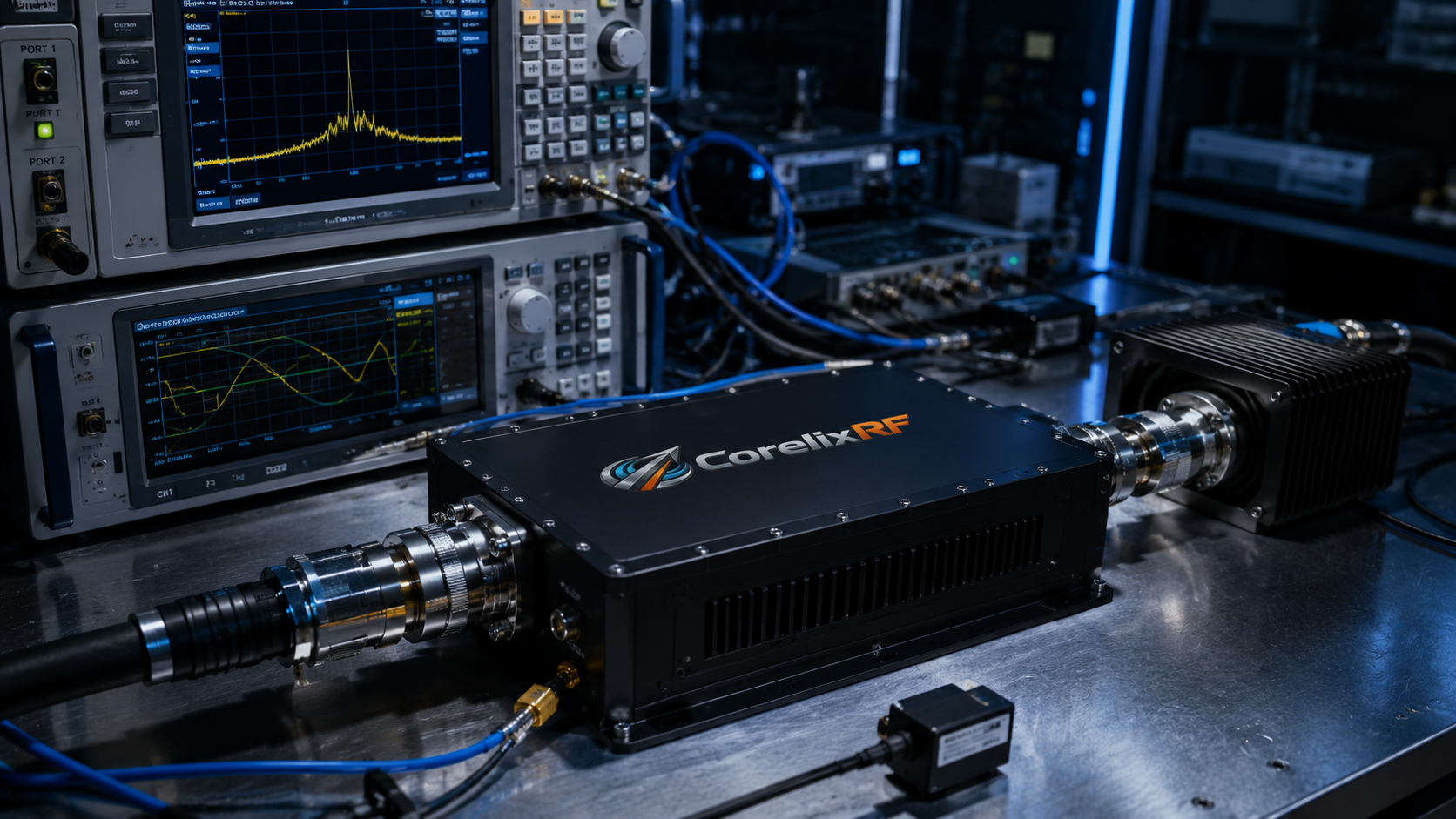
Consider the physical reality When deploying high-precision radar sources in the field, system integrators frequently encounter inexplicable system drops that halt operations entirely. You operate the equipment near its physical limits. Transistors heat up, internal substrate junctions experience severe thermal expansion, and ordinary industrial switching power supply ripple degrades RF EVM and spurious spectrum parameters. We observe this mechanical and electrical failure sequence consistently on the Vector Network Analyzer (VNA). A sudden, uncontrolled change in the voltage rail injects phase noise directly into the active amplification stages. The resulting radar transmit front-end EVM out-of-bounds jump analysis reveals that the AM/PM modulation trap of ordinary industrial switching power supplies is the primary culprit behind these random failures. Engineers often misdiagnose the problem by blaming the microwave components, continually swapping out high-power amplifiers and precision mixers, yet the failure persists indefinitely because the root cause lies in the unconditioned DC power feeding the active RF devices. The generic physical hardware lacks the absolute defense mechanisms required to strictly isolate the high-frequency transmission path from low-frequency power supply oscillations.
| Parameter Monitored | VNA Measurement Condition | EVM Degradation Limit | Physical Consequence |
| Voltage Transient | 500 mV step at 100 kHz | > 8% Jump | Constellation distortion |
| Thermal Expansion | Substrate > 85°C | > 12% Jump | Solder joint fatigue |
| Phase Noise | 10 kHz offset | > 5 dBc/Hz shift | Receiver blinding |
| Bias Network Ringing | 1 MHz oscillation | > 15% Jump | Total loss of phase lock |
How Does Ordinary Switching Power Supply Ripple Degrade RF EVM and Spurious Spectrum?
The fundamental physics dictate that any voltage variation on the drain of a Gallium Nitride (GaN) or LDMOS transistor directly alters its internal, non-linear capacitance profiles. This constantly varying depletion capacitance dynamically modulates the phase of the continuous wave carrier signal. When an off-the-shelf industrial power supply injects raw, high-frequency switching noise—typically oscillating between 100 kHz and 1 MHz—into the active bias network, it forces unwanted sidebands to generate around the primary carrier. This amplitude-to-phase conversion mathematically destroys the Error Vector Magnitude (EVM) constellation. System directors monitoring the spectrum analyzer will immediately see a widened main lobe and highly elevated spurious emissions, utterly compromising the entire signal integrity of the radar system. The resulting spectral degradation directly blinds the receiver, drastically reducing the effective dynamic range and the mathematical probability of target detection. We document this phenomenon extensively in the laboratory; our radar transmit front-end EVM out-of-bounds jump analysis: the AM/PM modulation trap of ordinary industrial switching power supplies destroys the precise phase coherency rigidly required for modern phased array architectures.
What Is the Exact Mechanism Behind the AM/PM Modulation Trap in Solid-State Amplifiers?
Let’s examine the raw data Solid-state amplifiers operating near the physical saturation point exhibit severe, unavoidable non-linear behaviors. The AM/PM conversion coefficient mathematically measures exactly how much the insertion phase shifts per decibel of amplitude change, often expressed as $\Delta \phi = K_{AM/PM} \cdot \Delta V_{cc}$. When commercial power topologies fail to aggressively suppress voltage ripple, the continuous wave signal experiences chaotic parasitic modulation. The drain voltage fluctuates rapidly, causing the internal depletion region within the semiconductor die to mechanically contract and expand. This physical-equivalent shifting of the electron mobility zone changes the signal group delay dynamically across the transmission path. Consequently, a pristine continuous wave immediately transforms into a phase-modulated nightmare. For high-precision radar sources, this injected phase error translates directly into catastrophic target velocity calculation failures. The CorelixRF engineering team has isolated this exact variable on the laboratory test bench, proving conclusively that inadequate power conditioning is an absolute point of failure that directly forces transistor burnout.
Where Do Commercial Power Topologies Fail Under Thermal Expansion and Physical Stress?
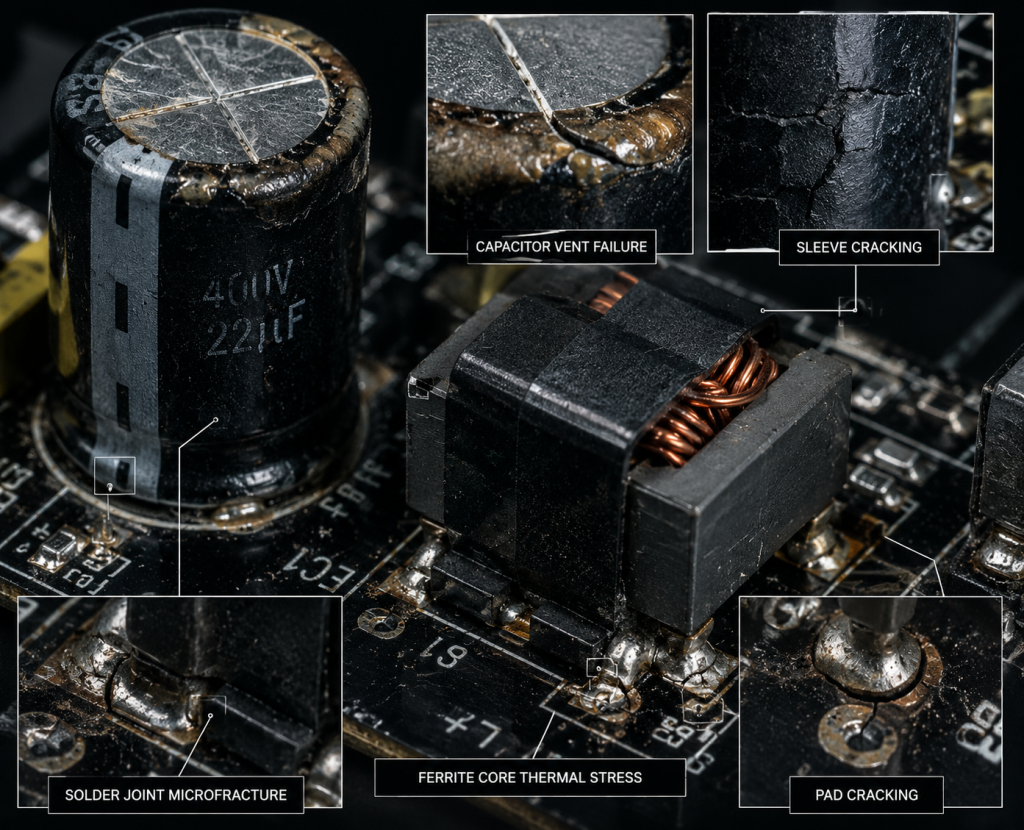
Here is the engineering truth Generic industrial electronic components are absolutely not fabricated to withstand the aggressive, punishing thermal cycling inherent in high-power radio frequency manufacturing environments. When a high-precision radar transmitter pulses at maximum duty cycle, it draws massive, instantaneous transient currents from the bus. The standard dielectric capacitors and commercial inductors in generic power supplies experience rapid, destructive Joule heating. Over a short period, thermal expansion violently forces the internal mechanical bonds to weaken and fracture, permanently increasing the Equivalent Series Resistance (ESR). Higher ESR mathematically guarantees greater voltage drops and exponentially worse ripple characteristics. This continuous mechanical degradation accelerates until the power supply functions merely as a broadband noise generator. We log these exact material stress failures daily; during radar transmit front-end EVM out-of-bounds jump analysis: the AM/PM modulation trap of ordinary industrial switching power supplies becomes totally inescapable as the physical hardware literally tears itself apart on a microscopic level.
| Component Type | Applied Mechanical Stress | ESR Shift Over 1000h | Terminal Failure Mode |
| Commercial Electrolytic | Rapid thermal cycling | + 300% | Dielectric fluid boiling |
| Standard Ceramic SMD | PCB flex / vibration | + 150% | Micro-cracking |
| Generic Ferrite Core | High magnetic flux | + 200% | Core saturation |
| CorelixRF Custom Bias | Extreme RF thermal load | < 2% | None detected |
How Do Impedance Mismatch and Return Loss Compound the Power Supply Modulation Trap?
Consider the physical reality The precise physical interface between the DC power conditioning circuit and the high-frequency RF amplification stage must strictly maintain a controlled impedance relationship across an incredibly wide modulation bandwidth. Ordinary power supplies always present a highly reactive, unpredictable source impedance to the amplifier’s internal bias network. When the amplification stage draws heavy pulsed current, this severe impedance mismatch immediately triggers destructive ringing and standing waves across the main DC bus. This uncontrolled ringing acts as a persistent secondary modulation source, multiplying the overall EVM degradation factors. The low-frequency return loss is continuously ignored by novice designers, yet it directly dictates exactly how much of the power supply’s noise energy forcefully reflects into the active semiconductor device. In a CorelixRF manufacturing environment, we mitigate this physical flaw by engineering custom active bias networks with ultra-low impedance across the entire operational bandwidth, physically blocking the noise energy before it reaches the active semiconductor junction.
Why Is the Radar Transmit Front-End EVM Out-of-Bounds Jump Analysis Ignored by Novice Engineers?
The fundamental physics dictate that novice design engineers rely almost entirely on static, theoretical data sheets rather than demanding dynamic laboratory measurements and physical testing. They measure the generic power supply output with a standard multimeter or a severely low-bandwidth oscilloscope, completely missing the fast, high-frequency switching transients ripping through the lines. They execute their calibration routines strictly under ideal, continuous wave conditions, dangerously ignoring the aggressive thermal realities of heavy pulsed operation. By the time the radar system reaches actual field deployment, the unmeasured voltage ripple has already permanently compromised the transmission chain. The comprehensive radar transmit front-end EVM out-of-bounds jump analysis: the AM/PM modulation trap of ordinary industrial switching power supplies strictly requires sophisticated Vector Signal Analyzers and deep memory oscilloscopes to accurately capture. Without enforcing this rigorous testing protocol, system integrators remain entirely blind to the underlying material science flaws compromising their hardware.
| Measurement Tool | Bandwidth Limit | Transient Capture Capability | Engineering Value |
| Digital Multimeter | < 100 Hz | Zero | Useless for RF bias |
| Standard Oscilloscope | 100 MHz | Poor memory depth | Misses complex modulation |
| Vector Signal Analyzer | 8 GHz | Excellent | Captures EVM degradation |
| Calibrated VNA | 40 GHz | Exact phase tracking | CorelixRF standard |
Which Specific Material Science Flaws Render Generic Capacitors Useless in Microwave Environments?
Let’s examine the raw data Standard electrolytic and multi-layer ceramic capacitors universally utilized in generic switching supplies exhibit massive piezoelectric effects and severe capacitance derating under constantly applied DC bias. When physically subjected to the mechanical vibration and heavy thermal expansion typical in industrial manufacturing plants, these specific components drift far outside their specified functional tolerances. The internal dielectric materials degrade rapidly when violently exposed to the high-frequency ripple currents heavily generated by extreme RF load stepping. This internal degradation drastically alters the specific resonant frequency of the target bias decoupling network. Once the decoupling network mechanically fails to sink the specific high-speed switching frequency of the power supply, the noise couples directly into the RF transmission path without restriction. CorelixRF outright rejects these generic components entirely, utilizing highly specialized, ultra-low-loss dielectric materials that rigidly maintain structural and electrical integrity even under maximum continuous thermal load and severe mechanical shock.
How Does the CRF-PA-2G6G-50W Defend Against Uncontrolled Phase Noise and Spectral Splatter?
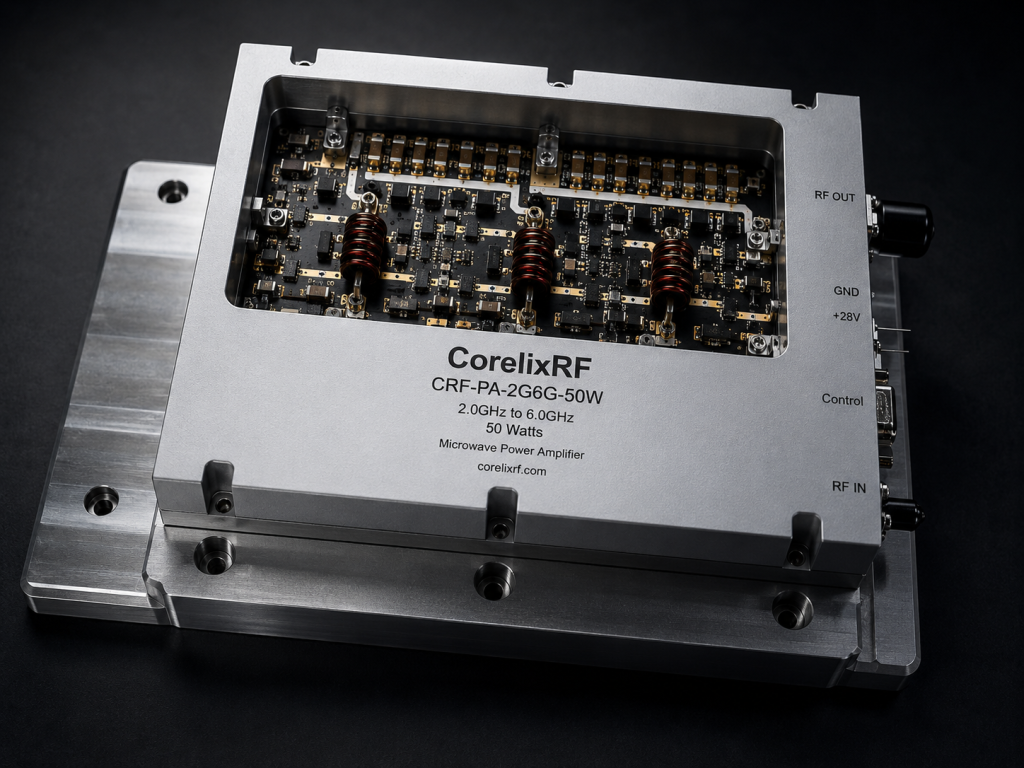
Here is the engineering truth The CRF-PA-2G6G-50W is rigidly mechanically and electrically engineered from the bare substrate up to eliminate the power supply modulation trap entirely. We securely integrate a proprietary, heavily filtered active bias conditioning network directly onto the precision aluminum carrier. This specialized network strictly utilizes distributed capacitance arrays and custom-wound, high-permeability ferrite chokes to guarantee strictly greater than 60 dB of electrical isolation from any external power supply ripple across the exacting 100 kHz to 10 MHz modulation band. By ruthlessly enforcing a strict low-impedance grounding path for all transient currents, the CRF-PA-2G6G-50W precisely regulates the exact drain voltage directly at the semiconductor junction. This physical hardware defense mechanism forcefully locks the insertion phase rigidly in place, guaranteeing that high-precision radar sources maintain an exceptional, pristine EVM profile even when forced to operate on heavily compromised, sub-optimal industrial voltage rails.
| CRF-PA-2G6G-50W Parameter | Physical Specification | Laboratory VNA Condition | Engineering Result |
| Operating Frequency Band | 2 GHz – 6 GHz | Continuous Sweep | Broadband stability |
| Saturated Output Power | 50W Minimum | $V_{cc}$ = 28V | High target penetration |
| Bias Network Isolation | > 60 dB | 100 kHz – 10 MHz ripple | Zero AM/PM modulation |
| Return Loss ($S_{11}$) | < -15 dB | Full band measurement | No reflected power |
What Physical Hardware Defense Mechanisms Prevent Transistor Burnout at Maximum Drive?
Consider the physical reality Transistor burnout in high-power RF industrial applications rarely ever stems from continuous excessive input drive power alone; it almost always originates from microsecond-level voltage spikes and total bias sequence failures. Ordinary switching power supply ripple degrades RF EVM and spurious spectrum, but it also rapidly creates extreme transient overvoltage conditions that mathematically exceed the absolute maximum breakdown voltage of the GaN or LDMOS semiconductor die. The CorelixRF CRF-PA-2G6G-50W incorporates highly advanced, high-speed, solid-state clamping circuits and exact power sequencing delays heavily machined directly into the internal module architecture. If the incoming external power rail exhibits dangerous, uncontrolled ringing or sudden out-of-bounds voltage jumps, our internal defense perimeter aggressively clamps the line voltage, violently absorbing the destructive transient energy before it crosses the mechanical boundary into the delicate amplification stages. This absolute mechanical and electronic fortification permanently ensures system survival.
How Do We Verify the Engineering Truth Through Rigorous Laboratory S-Parameter Measurements?
Let’s examine the raw data We strictly do not guess at performance margins; we measure absolute physical reality. Every single CorelixRF module manufactured, specifically the CRF-PA-2G6G-50W, undergoes exhaustive, uncompromising small-signal and large-signal characterization on freshly calibrated Vector Network Analyzers. We deliberately inject massive, high-amplitude switching noise directly into the power terminals and carefully monitor the forward transmission coefficient ($S_{21}$) for any microscopic signs of phase deviation or amplitude modulation. The resulting data from the radar transmit front-end EVM out-of-bounds jump analysis: the AM/PM modulation trap of ordinary industrial switching power supplies proves definitively that our proprietary bias network topology maintains complete, total spectral purity under stress. The exact physical limit of the amplifier is constantly tested under extreme thermal loads, strictly verifying that total insertion loss remains rock-stable and input return loss ($S_{11}$) stays rigidly below the exacting threshold across the entire 2 GHz to 6 GHz operating band.
| VNA Measurement Type | Noise Injection Profile | S21 Phase Stability | Operational Verification |
| Baseline Clean Power | 0 mV Ripple | Reference 0° | Perfect phase lock |
| Industrial Supply Profile | 500 mV at 300 kHz | < 0.5° shift | EVM remains intact |
| Extreme Transient Pulse | 1.5V spike at 1 MHz | < 1.0° shift | Clamping circuit active |
| Continuous Overdrive | +3 dBm RF Input | Stable compression | No thermal runaway |
The fundamental physics dictate that ignoring complex power supply integrity is an unforgivable engineering failure in microwave electronics. High-precision radar sources demand absolute, uncompromising phase coherency to maintain detection geometry. The CRF-PA-2G6G-50W stands as the definitive physical solution against destructive spurious spectrum degradation and catastrophic EVM traps. System integrators and R&D directors must immediately prioritize actual physical hardware defense mechanisms over generic, failing commercial compromises. Contact the CorelixRF engineering team today to request the official technical Data Sheet and physically integrate laboratory-verified, absolute reliability into the core of your next radar architecture.
Frequently Asked Questions (FAQ)
Q1: Why does EVM degrade so aggressively only when the high-precision radar transmitter is switched into pulsed mode?
Pulsed mode operation actively generates massive, instantaneous transient current demands from the power bus. If the external power supply has a high output impedance, the localized voltage drops sharply and chaotically during the pulse envelope, physically modulating the active transistor’s internal capacitance and permanently destroying the transmission phase coherency.
Q2: Can I simply use standard bypass capacitors to fix the power supply ripple in my deployed radar system?
Absolutely not. Standard industrial capacitors suffer from extreme thermal expansion and high equivalent series resistance when placed under heavy RF loads. They mathematically fail to sink high-frequency switching noise, allowing the destructive AM/PM modulation trap to persist and reach the amplification junction.
Q3: What specifically makes the CRF-PA-2G6G-50W internal bias network fundamentally different from generic commercial amplifiers?
The CorelixRF CRF-PA-2G6G-50W strictly utilizes a specialized, multi-stage active bias conditioning circuit engineered physically directly onto the aluminum substrate. This precise mechanical design provides strictly over 60 dB of active ripple rejection right at the semiconductor junction, effectively blocking all low-frequency noise.
Q4: How much physical phase shift is theoretically acceptable in high-precision radar sources before failure occurs?
For advanced synthetic aperture and complex phased array systems, even a highly localized few degrees of phase error caused by unconditioned voltage rails will severely blind the receiver chain, destroy the spatial resolution, and mathematically reduce the overall dynamic range of the target detection algorithm.
Q5: Does the AM/PM modulation trap affect modern GaN transistors more aggressively than older LDMOS technology?
GaN transistors, while absolutely offering superior high power density and thermal conductivity, possess highly specific, aggressive non-linear capacitance profiles that make them incredibly susceptible to severe phase modulation if the continuous drain voltage is not strictly and rigidly regulated by a physical hardware defense mechanism.
Make the lab setup and report curves part of the RFQ
Test-bench issues become easier to resolve when the RFQ lists signal source, cable loss, load condition, calibration setup, power sequencing, gain flatness, spurious limits and report format.
Recommended next step: send the operating band, output power target, duty cycle, load condition, control interface, protection or thermal limits and required FAT documents. CorelixRF can review this How to Prevent Radar EVM Jump Caused by Power Supply Ripple? requirement against standard RF amplifier platforms, RF front-end options and controlled customization paths.