
A test bench engineer watches their spectrum analyzer trace suddenly jump. An unexplainable spur ruins a perfectly calibrated measurement. False triggers on weak control pins ruin days of radar subsystem validation. Here lies the deal: high-current return interference from poor system grounding destroys signal integrity. 30 seconds of unstable bias current ruins an expensive prototype. We present a rigorous engineering method for constructing robust RF front-ends. CorelixRF approaches this problem with sheer physical principles and strict component selection.
What Causes High-Current Return Interference On RF Test Benches?
● Grounding loop fundamentals
● VNA trace anomalies
● High-power saturation effects
Engineers often face mysterious trace collapses when pushing amplifiers into saturation. But here’s the kicker: these anomalies stem from inadequate return paths rather than faulty active devices. When driving a 50W output module, significant DC current flows back through shared chassis grounds. This current finds one path of least electrical resistance. Often, that path travels straight through delicate digital control lines. We observe this exact phenomenon during continuous wave testing on radar components. A spectrum analyzer might display sudden wideband noise spikes across a 6,000-8,000 MHz sweep. These spikes represent ground bounce modulating your carrier frequency. A 28 VDC supply drawing substantial amps requires massive grounding planes. Without dedicated return paths, transient spikes easily exceed logic threshold voltages on weak pins. Test benches combining multiple high-power devices suffer exponentially from this architectural flaw. Standard commercial off-the-shelf components lack sufficient isolation for such rigorous environments. You must scrutinize every grounding point across your entire test setup.
Typical Return Current Paths
| Return Path Medium | Electrical Resistance | Interference Risk Level |
| Dedicated Copper Bus | < 1 milliohm | Negligible |
| Shared Chassis Ground | 10-50 milliohms | Moderate |
| Braided Coax Shield | > 100 milliohms | Severe |
| Ribbon Cable Ground | > 500 milliohms | Critical |
How Do Grounding Loops Degrade VNA Noise Floors?
● Coaxial shield currents
● Dynamic range reduction
● Calibration invalidation
A Vector Network Analyzer demands absolute electrical silence from its surrounding environment. What’s the real story? Grounding loops actively inject broadband noise directly into VNA receiver ports. When ground potentials differ between signal generators and power amplifiers, equalizing currents flow. These currents travel along coaxial cable shields connecting your precision instruments. As RF energy travels from 6,000-8,000 MHz, external low-frequency noise modulates test signals. We frequently see noise floors rise by 10 dB during high-power amplifier evaluation. This degraded dynamic range completely masks low-level spurious emissions from your device under test. An integrated communication system test requires measuring harmonics down near -60 dBc. Ground loops make such precise measurements physically impossible. Furthermore, these circulating currents invalidate painstaking systematic error calibrations. An engineer might spend two hours calibrating a test bench meticulously. One poorly grounded power supply connection immediately destroys that entire calibration effort. Hardware selection must prioritize modules with massive, machined aluminum housings for ideal grounding.
VNA Performance Degradation Factors
| Impairment Source | Effect On Measurement | Typical Severity |
| Coaxial Shield Current | Raised Noise Floor | 5-15 dB penalty |
| Differing Ground Potentials | Phase Measurement Error | 2-10 degrees |
| Unfiltered Power Lines | Spurious Tones Appear | -40 dBc artifacts |
| RF Leakage | Calibration Drift | Requires recalibration |
Why Do Weak Current Pins Experience False Triggers During High-Power Tests?
● Logic threshold crossing
● Transient voltage spikes
● State machine corruption
Digital control pins operate with minimal current and tight voltage margins. Here lies an interesting fact: pushing 50 W of RF power generates massive localized electromagnetic fields. A poorly shielded RS485 communication line acts like an unintended receiver antenna. High-current transients on shared ground planes cause local reference voltages bouncing violently. A logic low state suddenly registers as a logic high state due toward reference shifting. This false trigger completely scrambles automated test scripts running continuous evaluation cycles. In aviation control validation setups, such an event shuts down safety-critical transmission tests prematurely. We trace these failures back directly toward inadequate internal module isolation. Standard amplifiers often route sensitive logic traces adjacent near high-current DC feeds. An instantaneous current draw during an RF pulse induces massive crosstalk onto those traces. CorelixRF solves this by physically separating control interfaces from power input sections. Proper hardware architecture demands optical isolation or robust differential signaling for all weak pins.
Logic Pin Trigger Mechanisms
| Trigger Mechanism | Root Cause | Preventive Engineering Action |
| Ground Bounce | High localized return current | Implement star grounding |
| Inductive Crosstalk | Parallel routing of DC and logic | Maintain strict physical separation |
| RF Rectification | Unfiltered RF entering logic pins | Install low-pass feedthrough capacitors |
| EMI Susceptibility | Poorly shielded interconnects | Use double-shielded twisted pair |
What Are System-Level Link Budget Impacts Of Poor Matching?
● Reflected power dynamics
● Gain flatness degradation
● Source pull effects
Impedance mismatches create severe standing waves that destroy predictable system performance. Let’s look at facts: a 2:1 Input VSWR creates significant reflections back toward your signal source. These reflections alter output impedance characteristics regarding your driving synthesizer. This phenomenon, known as source pull, causes frequency instability alongside phase noise degradation. When constructing a test bench for satellite communication links, absolute stability remains non-negotiable. Poor matching across a 6,000-8,000 MHz band severely impacts your cascaded gain flatness. You might design for a tight ±4 dB flatness envelope. However, mismatched interfaces create severe ripples that exceed those specifications easily. These ripples complicate calibration routines and mask true device behavior. Furthermore, reflected energy dissipates as pure heat within your front-end components. This unnecessary thermal load accelerates component aging and alters operating characteristics dynamically. Proper hardware selection requires modules boasting rigorous internal matching networks. A stable 50-ohm impedance guarantees maximum power transfer and predictable link budget calculations.
Link Budget Mismatch Penalties
| VSWR Condition | Return Loss | Power Reflected |
| 1.2:1 | 20.8 dB | 0.8% |
| 1.5:1 | 14.0 dB | 4.0% |
| 2.0:1 | 9.5 dB | 11.1% |
| 3.0:1 | 6.0 dB | 25.0% |
How Does The CRF-PA-6000M8000M-50W Address Front-End Integration Constraints?
● Mechanical integration profile
● Thermal management approach
● Broad frequency coverage
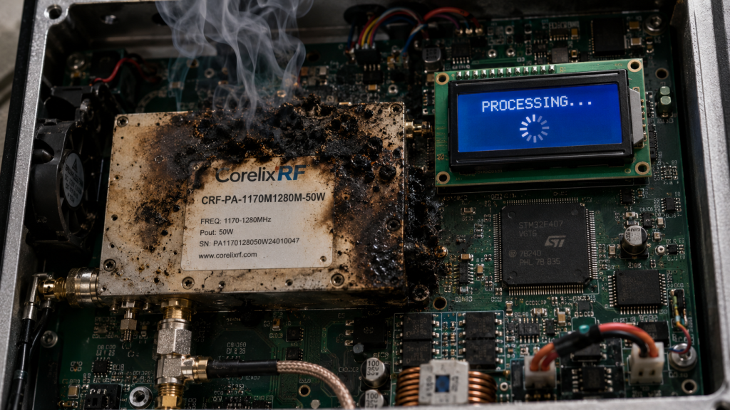
Integrating power amplifiers into dense test racks poses significant physical and electrical challenges. Ready for one good part? CorelixRF engineers machine each chassis from solid aluminum, yielding a compact 240x150x44.5mm package. This rugged construction provides an exceptional grounding plane for all internal sub-circuits. We eliminate ground bounce by terminating high-current returns directly into this massive thermal sink. Our module delivers 50 W of rated output power efficiently across a wideband 6,000-8,000 MHz range. A high 47 dB gain characteristic means you need minimal drive power. You can drive this unit directly from standard laboratory signal generators outputting 0 dBm. We rely upon rigorous air cooling forcing heat away during continuous wave operation. Internal architecture strictly isolates each RF path away from DC distribution networks. This physical separation prevents high-power RF from coupling backward into your weak current control lines.
CRF-PA-6000M8000M-50W Core Specifications
| Parameter | Min | Typ | Max | Units |
| Frequency Range | 6,000 | – | 8,000 | MHz |
| Rated Output Power | 50 | – | – | W |
| Gain | 47 | – | – | dB |
| Input VSWR | – | – | 2:1 | Ratio |
What Role Does Built-In Protection Play In Mitigating Ground Faults?
● VSWR protection thresholds
● Over-voltage safeguards
● Thermal shutdown mechanisms
Test bench environments inherently involve frequent connection changes and occasional operator errors. Here rests one bottom line: operating a high-power amplifier without complete protection invites catastrophic failure. A disconnected output cable instantly creates an infinite VSWR condition. Without rapid intervention, reflected energy destroys costly internal transistor junctions within microseconds. Our CRF-PA-6000M8000M-50W incorporates high-speed VSWR monitoring detecting these catastrophic mismatches instantly. Upon detecting an unsafe reflection, protection circuitry immediately drops internal bias voltage. This action suppresses RF generation before permanent physical damage occurs. Furthermore, ground faults often induce transient over-voltage conditions on primary DC supply lines. Built-in over-voltage protection clamps these dangerous spikes, shielding sensitive downstream components. We also integrate rigorous over-temperature sensing directly near high-power dissipation zones. If forced air cooling fails, our module gracefully shuts down before reaching critical thermal limits. These autonomous hardware safeguards prevent temporary grounding anomalies becoming expensive equipment casualties.
How Do 28 VDC Power Architectures Stabilize System Grounding?
● Current draw reduction
● Wire gauge requirements
● Supply regulation benefits
Choosing appropriate operating voltages dictates overall system stability and wiring complexity. Consider this specific detail: utilizing a 28 VDC supply significantly lowers total current requirements compared against 12 VDC systems. Delivering 50 W of RF power at lower voltages demands enormous DC currents. These massive currents require extremely thick cables and exacerbate voltage drops across grounding planes. Operating at 28 VDC halves required current for equivalent power levels. This reduction minimizes resistive heating within wiring harnesses and lowers ground bounce magnitude. A 28 VDC standard represents common aviation control and military system voltages. Our modules integrate seamlessly into these existing high-reliability power architectures without complex conversion. We design internal switching regulators handling slight input voltage variations gracefully. This robust regulation guarantees constant RF output power despite minor fluctuations on facility power grids. A stable DC foundation directly translates into pristine RF spectral purity and predictable test results.
What Mechanical Considerations Prevent RF Leakage In Test Environments?
● Chassis milling techniques
● Connector integration
● EMI gasketing
Electromagnetic interference wreaks havoc on precision measurement equipment located near power amplifiers. What remains our secret? Absolute mechanical integrity prevents stray RF energy escaping from amplifier housings. We construct our CRF-PA-6000M8000M-50W using precise CNC milling techniques from solid aluminum blocks. This monolithic approach eliminates seams and joints where high-frequency waves typically leak. We utilize high-quality N-Female connectors for both RF input and output ports. These robust connectors provide excellent shielding effectiveness and repeatable impedance characteristics across countless mating cycles. Any mechanical interface between chassis lids and bases utilizes specialized EMI gasketing. This conductive material compresses tightly, maintaining electrical continuity around every enclosure perimeter. We completely isolate internal compartments, separating active RF stages away from control electronics. These rigorous mechanical engineering practices guarantee an exceptionally low noise floor near -40 dBm/MHz. Your sensitive test equipment remains undisturbed by radiated emissions originating from our power module.
Why Are RS485 Control Interfaces Superior For Noisy RF Environments?
● Differential signaling logic
● Noise immunity characteristics
● Long-distance routing
Controlling equipment accurately within a high-power RF test cell requires robust communication protocols. Here stands true engineering logic: standard single-ended logic protocols like TTL fail miserably amidst these harsh environments. Any high-current transient upon a shared ground plane alters logical states instantly. We outfit each CRF-PA-6000M8000M-50W with an RS485 control interface specifically combatting this vulnerability. RS485 utilizes differential signaling, meaning data transmits over two complementary wires. External electromagnetic interference typically couples equally onto both wires simultaneously. Receiver circuits only look at voltage differences between those two lines. This common-mode rejection effectively cancels out noise induced by poor grounding or RF radiation. You can route RS485 cables across long distances through noisy industrial test facilities reliably. It guarantees automated test systems maintain absolute command over amplifiers under all conditions.
How Should You Execute Final Hardware Selection For Radar Component Validation?
● Evaluating data sheets
● Verifying harmonic performance
● Evaluating long-term reliability
Selecting correct hardware dictates ultimate success regarding your radar validation campaigns. Let’s wrap this entire discussion up: you must scrutinize manufacturer data sheets demanding rigorous engineering truth. Look beyond peak power claims and examine continuous wave performance under mismatched conditions. Our CRF-PA-6000M8000M-50W guarantees harmonics strictly controlled under -10 dBc alongside spurious emissions below -60 dBc. These strict parameters ensure your test signals remain clean, preventing false target generation during radar evaluation. Assess internal thermal management strategies, as continuous operation requires substantial cooling reserves. We provide complete mechanical drawings facilitating seamless integration inside your specific test racks. Demand equipment manufactured under strict quality frameworks like ISO 9001 and GJB 9001C. This certification guarantees consistent lot-to-lot performance, allowing your test bench running predictably for decades. Hardware selection never involves finding cheapest options; it requires securing uncompromising reliability.
Robust test bench construction requires eliminating high-current return interference through strict grounding practices. Our CRF-PA-6000M8000M-50W provides unmatched physical isolation, protecting weak control pins against destructive false triggers. Choose modules boasting massive machined housings alongside differential RS485 interfaces securing absolute measurement integrity. Contact CorelixRF engineering immediately requesting detailed pattern files evaluating this wideband amplifier inside your specific system architecture.
Frequently Asked Questions
Q1: What causes high-current return interference?
High-current return interference occurs when substantial DC currents flow through inadequate shared grounding paths. This causes local reference voltages fluctuating wildly and corrupting sensitive signals.
Q2: How does our CRF-PA-6000M8000M-50W prevent false triggers? It prevents false triggers by physically isolating RF paths away from control electronics. It utilizes a massive aluminum chassis providing ideal grounding alongside differential RS485 communication protocols.
Q3: Why do poor matching systems degrade VNA calibration?
Poor impedance matching creates severe reflected power altering source stability. It introduces circulating currents along coaxial shields, completely invalidating precision systematic error calibrations.
Q4: What protection features exist within this CorelixRF amplifier? This module includes high-speed monitoring circuits actively protecting internal components against over-voltage spikes. It prevents damage from extreme temperatures and catastrophic VSWR mismatches during test operations.
Q5: How should engineers handle thermal management regarding 50W RF modules? Engineers must provide adequate air cooling pathways and verify secure mechanical mounting onto heavy rack structures. This facilitates rapid heat transfer away from internal transistor junctions.
Make the lab setup and report curves part of the RFQ
Test-bench issues become easier to resolve when the RFQ lists signal source, cable loss, load condition, calibration setup, power sequencing, gain flatness, spurious limits and report format.
Recommended next step: send the operating band, output power target, duty cycle, load condition, control interface, protection or thermal limits and required FAT documents. CorelixRF can review this How to Fix False Triggers With Proper RF Test Bench Grounding? requirement against standard RF amplifier platforms, RF front-end options and controlled customization paths.