
Engineering Decision and RFQ Checklist
This page is now treated as a primary RF engineering guide for ATE fixtures, grounding, protection events and repeatable sweep evidence. Use the checklist below to turn the article into a buyer-ready RFQ and factory review package.
| Decision Area | What to Confirm | Evidence to Request |
|---|---|---|
| Operating condition | Band, output power, duty cycle, waveform or sweep condition. | Rated operating table and test setup notes. |
| Interface | RF connector, load or antenna condition, control interface and power supply. | Interface drawing, control table and connector limits. |
| Reliability | Thermal path, protection behavior, enclosure airflow and environmental margin. | Thermal data, protection event notes and inspection records. |
| Acceptance | Gain, flatness, power, mismatch behavior, stability or repeatability limits. | FAT checklist, calibration state and final test curves. |
- RFQ checklist – convert requirements into buyer-ready fields.
- RF configurator – summarize band, power, interface and duty-cycle requirements.
- Delivery documentation – align test curves and FAT-style evidence.
- Case studies – compare how engineering issues become procurement decisions.
- Contact CorelixRF – send the requirement package for review.
Primary Topic Hub and RFQ Path
This primary guide now consolidates related RF engineering references. Use it for the current technical explanation, RFQ preparation, factory review and delivery documentation path.
- How to Prevent OTA Signal Anomalies During High-Power Sweeps? – consolidated reference
The purpose is to reduce duplicate SEO pages while keeping buyers on one stronger engineering guide with clearer RFQ and documentation paths.
- RFQ checklist – prepare band, power, duty cycle, interface, cooling and acceptance inputs.
- RF configurator – turn project requirements into a first engineering brief.
- Delivery documentation – align test curves, inspection records and FAT-style evidence.
- Case studies – review how CorelixRF frames RF problems for buyer decisions.
- Contact engineering sales – submit the documented scope for review.
Automated Test Equipment environments often punish RF engineers with mysterious signal degradation. False failures waste time while operators swap expensive cables aimlessly. Here’s the deal, understanding fundamental microwave physics solves these measurement errors permanently. Backed by 30 years of manufacturing heritage and 400 dedicated employees, CorelixRF brings authentic engineering reality into your production facility.
1. What Causes ATE Signal Anomalies During Production Testing?
● Factory Floor Environmental Extremes
● Connector Wear Mechanisms
● Signal Path Degradation
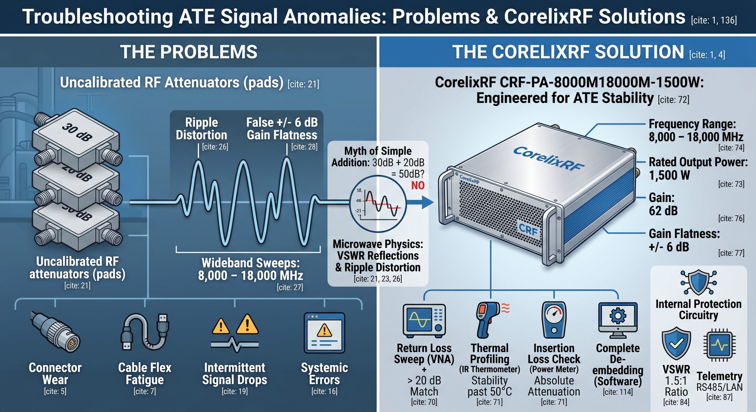
You might be wondering, why do perfectly good amplifiers fail automated factory tests? Industrial ATE setups present brutally demanding physical conditions. Heavy mechanical relays click endlessly during 24-hour manufacturing cycles. Coaxial test leads bend constantly as technicians swap modules. Operators often stack multiple fixed attenuators indiscriminately. Every single N-type connector interface adds mismatch uncertainty into your measurement path. High-power RF energy rapidly heats passive components. Thermal expansion physically alters internal impedance characteristics across different frequency bands. A calibration working flawlessly at 8,000 MHz might fail catastrophically near 18,000 MHz. Many test engineers ignore small insertion loss variations initially. These tiny errors compound exponentially through complex routing matrices. Signal integrity degrades severely before reaching your sensitive receivers. False VSWR alarms trigger frequently during wideband swept measurements. Your spectrum analyzer suddenly displays elevated noise floors without warning. These specific symptoms point toward physical layer degradation rather than internal device failure. Real-world factory floors lack climate control perfection found inside metrology labs. Dust particles contaminate precision interfaces daily. Torque wrenches sit improperly calibrated inside technician toolboxes. Fixing such systemic errors requires returning back toward basic microwave transmission line principles.
1. Common ATE Physical Anomalies | Impact | Resolution
Connector Dust Contamination | Increased insertion loss | Regular alcohol cleaning protocols
Cable Flex Fatigue | Phase shifting | Armored cable implementation
Relay Contact Wear | Intermittent signal drops | Routine switch matrix replacement
Improper Torque | Random VSWR spikes | Calibrated wrench enforcement
2. Why Do Uncalibrated Cascaded Attenuators Distort Gain Flatness?
● The Myth Of Simple Addition
● Standing Wave Generation
● Flatness Distortion Effects
But here’s the kicker, stacking fixed RF pads seems mathematically trivial. You bolt a 30 dB block onto a 20 dB block, expecting 50 dB total reduction. Microwave physics strongly disagrees with simple arithmetic regarding cascaded networks. Each individual pad possesses its own unique voltage standing wave ratio. Cascading two imperfect devices creates multiple internal reflection paths. Forward energy bounces back and forth between mismatched interfaces continuously. This trapped standing wave causes massive ripple across your swept frequency response. A supposed flat attenuation profile becomes a volatile sinusoidal curve. During wideband sweeps spanning 8,000 – 18,000 MHz, this ripple severity increases dramatically. An amplifier possessing genuine +/- 2 dB flatness suddenly reads +/- 6 dB falsely. Quality control supervisors reject perfectly good product units unfairly. Standard calibration procedures often skip characterizing these cascaded blocks as one unified measurement network. Metrology technicians calibrate their primary cables but leave cooling-mounted attenuators untouched. This specific omission guarantees distorted data recording permanently. You must shoot a full two-port calibration through every single passive element.
3. How Does VNA Calibration Plane Drift Affect Measurement Accuracy?
● Reference Plane Mechanics
● Thermal Phase Shifting
● Error Misdiagnosis
What’s the real story? Establishing an accurate reference plane remains absolutely mandatory for microwave validation. A Vector Network Analyzer mathematically removes systematic errors up until your specified calibration point. Moving test leads after saving this state invalidates all subsequent readings instantly. In busy factory settings, operators twist heavy WRD650 waveguide transitions constantly. Mechanical stress degrades phase stability within expensive armored assemblies. Temperature shifts inside production facilities cause internal dielectric materials expand. This expansion alters electrical length noticeably during long testing shifts. A reference plane calibrated at morning shift start drifts significantly by afternoon. High-frequency measurements up around 18,000 MHz suffer greatest degradation from thermal phase shifting. Measured gain flatness traces start tilting downwards automatically. System engineers mistake this tilt for actual power amplifier performance drop. We constantly remind radar integrators about verifying their reference planes hourly. Using electronic calibration modules helps speed up this mandatory verification process. Proper measurement discipline prevents costly hardware misdiagnosis.
2. VNA Drift Factors | Primary Cause | Severity Level
Dielectric Expansion | Ambient temperature shifts | High at 18 GHz
Mechanical Stress | Cable twisting | Moderate
Connector Loosening | Operator fatigue | Extreme
Adapter Wear | Repeated mating cycles | High
4. What Are Hidden Traps Of High-Power RF Component Testing?
● Thermal Compression Realities
● Dynamic Attenuation Shifts
● False Protection Triggers
This is where it gets interesting, pushing 1,500 Watts continuous wave energy changes everything. Low-power assumptions fail catastrophically inside high-power laboratory environments. Standard attenuators experience severe thermal compression when absorbing massive heat loads. A 50 dB pad might provide correct reduction at 1 Watt input. When blasted with full output power, its internal resistive film heats up drastically. Resistance values shift rapidly, altering both attenuation levels alongside input match characteristics. This thermal drift happens dynamically during long duration burn-in cycles. Your automated data logs capture an artificially drooping output power curve. The device under evaluation gets blamed for dropping power output. In reality, your measurement load simply changed its physical properties under thermal stress. Uncalibrated directional couplers also suffer from directivity degradation when connectors get hot. Reflected power readings spike artificially, triggering false VSWR protection shutdowns. Rigorous engineering requires using high-power, thermally stabilized termination blocks. We demand water-cooled or massive air-cooled dissipation systems for any reliable metrology setup.
5. How Can Engineers Identify Attenuator Mismatches On Production Floors?
● Return Loss Verification
● Time Domain Techniques
● Thermal Profiling
Ready for the good part? Spotting these specific measurement errors before they ruin your entire batch saves massive headaches. Start by examining your VNA return loss traces looking directly into your test load. An ideal matched load shows better than 20 dB return loss everywhere. If you cascade three separate pads together, watch that trace degrade rapidly. Periodic ripples appearing across your return loss display indicate multiple reflection points. Measure distance-to-fault using time domain transform features on your network analyzer. This advanced technique pinpoints exactly which connector interface causes maximum signal reflection. Swap out suspected bad connectors immediately with verified good components. Another practical method involves plotting insertion loss versus temperature during active operation. Aim an infrared thermometer directly at your high-power terminating load block. Watch how attenuation values change as external metal temperatures climb past 50°C. Quality hardware maintains stable electrical characteristics despite heavy thermal loading. Reject any passive component showing significant drift during these basic verification steps.
3. Floor Verification Methods | Required Tool | Target Metric
Return Loss Sweep | VNA | > 20 dB matching
Distance to Fault | VNA with TDR | Connector impedance
Thermal Profiling | IR Thermometer | Stability past 50°C
Insertion Loss Check | Power Meter | Absolute attenuation
6. Why Is CRF-PA-8000M18000M-1500W Engineered For ATE Stability?
● Wideband GaN Architecture
● Extreme Flatness Specifications
● Clean Spectral Purity
Here is the deal, we designed our CRF-PA-8000M18000M-1500W specifically for brutal integration environments. This heavy-duty unit delivers a rated output power of 1,500 W reliably. Operating continuously across an 8,000 – 18,000 MHz frequency range demands serious architectural integrity. We utilize advanced GaN technology, ensuring exceptional ruggedness under mismatched conditions. A minimum gain of 62 dB provides massive amplification for demanding electronic warfare applications. We guarantee overall gain flatness remains within a tight +/- 6 dB window. This specified flatness already accounts for realistic operational temperature variations from 0°C up until 50°C. A built-in adjustable gain range covering 20 dB allows precise system leveling. Such flexibility helps compensate for those inevitable cable losses mentioned previously. Our engineering team prioritized creating an exceptionally clean spectral output. Spurious emissions stay firmly pushed down below -60 dBc consistently. Harmonics remain strictly controlled between -15 and -8 dBc. You get raw, unadulterated fundamental frequency power exactly where needed most.
7. What Hardware Design Elements Prevent VSWR Protection Triggering?
● Tolerant Input Matching
● Lightning-Fast Telemetry
● Rugged Physical Interfaces
You might be wondering, how do we survive uncalibrated loads without failing? Our secret lies inside extremely robust internal protection circuitry. Our input VSWR specification sits at a highly tolerant 1.5:1 ratio. Real-world testing involves rapid relay switching, causing momentary infinite VSWR spikes. We implemented ultra-fast reverse power monitoring algorithms via our control interface. Whether using RS485 or LAN connections, telemetry updates happen almost instantaneously. Built-in protection handles over-voltage, over-temperature, over-drive, alongside severe VSWR events safely. Massive internal reflected energy dumping resistors absorb sudden mismatch shocks without destroying active GaN dies. We selected a rugged WRD650 waveguide output connector for maximum power handling. Waveguides eliminate fragile center pins found inside coaxial connectors completely. An N-Female input connector provides reliable, industry-standard interfacing for your arbitrary waveform generators. These deliberate physical design choices eliminate common points of failure observed during rigorous testing. True engineering reality dictates overbuilding critical RF transmission pathways.
4. CRF-PA-8000M18000M-1500W Core Specs | Parameter | Value
Frequency Range | Bandwidth | 8,000 – 18,000 MHz
Rated Output Power | CW Power | 1500 W
Gain | Amplification | 62 dB
Gain Flatness | Ripple | -6 to 6 dB
8. How Does Air Cooling Impact Continuous 1500W RF Power Delivery?
● Eliminating Liquid Leakage Risks
● High-Volume Thermal Extraction
● Temperature Dependent Stability
What’s the real story? Dissipating massive thermal waste requires serious mechanical consideration. Many competitors rely on complex liquid cooling loops prone to leaking. We opted for a highly optimized forced air cooling methodology instead. Operating directly from AC 380V±10% three-phase power supplies guarantees robust electrical delivery. High-volume industrial fans force ambient air across custom-machined aluminum heatsink fins. This thermal management system maintains safe internal junction temperatures even during continuous 1,500 W transmission. By keeping active components cool, we stabilize that critical +/- 6 dB gain flatness. Uncontrolled heat acts as the primary enemy destroying high-frequency phase stability. A well-cooled amplifier chassis ensures predictable performance during grueling 24-hour ATE cycles. We engineered our internal layout, minimizing thermal crosstalk between AC power supply units and sensitive RF modules. This precise spatial separation further enhances overall system reliability. Radar integrators trust this specific mechanical design during critical aviation control evaluations.
9. What Steps Ensure Correct Gain Flatness Verification In Labs?
● Absolute Power Baseline
● Slow Sweep Disciplines
● Matrix De-embedding
This is where it gets interesting, proving our datasheet specifications requires disciplined measurement techniques. Never rely solely on an uncalibrated spectrum analyzer display for absolute amplitude readings. Always utilize high-accuracy thermistor-based power meters for establishing your baseline power levels. Sweep your synthesized source slowly, allowing your power meter sufficient settling time. Fast sweeps mask narrow-band suck-outs caused by external connector mismatches. Characterize your entire output chain, including directional couplers, attenuators, and cables precisely. Store this complete loss matrix inside your automated test software securely. Subtract these external passive losses dynamically from your raw power readings. Only then will you see the true performance curve of our CRF-PA-8000M18000M-1500W amplifier. A measured noise floor reading better than -20 dBm/MHz confirms excellent dynamic range. Proper metrology separates amateur guesswork from professional engineering truth. We always supply necessary test data files for initial project review.
5. Lab Verification Protocol | Action | Reason
Thermistor Meter Usage | Power validation | Absolute accuracy
Slow Source Sweeping | Data gathering | Prevents trace masking
Complete De-embedding | Software subtraction | Removes passive loss errors
Baseline Floor Check | Spectrum analysis | Confirms -20 dBm/MHz spec
10. How Can System Integrators Optimize Their ATE Architecture Now?
● Hardware Replacement Strategies
● Calibration Protocol Enforcement
● Telemetry Integration
Ready for the good part? Upgrading your automated platforms requires decisive action today. Stop ignoring those mysterious high-frequency ripples appearing on your laboratory monitors. Replace chained attenuators with single, high-quality, high-power directional couplers immediately. Mandate daily VNA calibration plane verification protocols across your entire production floor. Investigate replacing fragile coaxial test runs with rigid waveguide sections wherever possible. Transition toward utilizing amplifiers designed specifically for harsh integration realities. The CRF-PA-8000M18000M-1500W offers optional forward and reverse power monitoring capabilities. Customizing these specific features allows seamless integration into your proprietary ATE software suites. Adding an optional GPIB communication interface expands legacy equipment compatibility significantly. Our factory holds strict ISO 9001 and GJB 9001C quality framework certifications. This manufacturing compliance guarantees exceptional consistency across every delivered unit. Take strict control over your testing environment by applying rigorous microwave discipline.
We summarized critical physical mechanisms behind distorted ATE measurements today. Eliminating uncalibrated cascaded attenuators restores absolute confidence within your gathered datasets. Adopt rigorous verification practices alongside robust hardware solutions like our CRF-PA-8000M18000M-1500W. Contact CorelixRF engineering support directly for detailed system-level architecture consultations.
Q1: What is ATE signal distortion?
ATE signal distortion refers to measurement inaccuracies caused by environmental stress, connector wear, and uncalibrated passive components.
Q2: How does a cascaded attenuator work?
A cascaded attenuator setup combines multiple pads, creating mismatched reflection planes that severely distort high-frequency gain flatness measurements.
Q3: Why do high-power RF modules require air cooling?
Air cooling dissipates extreme thermal loads generated by 1500W continuous transmission, preventing thermal compression and maintaining phase stability.
Q4: How can engineers verify VNA calibration planes accurately?
Engineers verify planes using Time Domain Reflectometry (TDR) and precision electronic calibration modules to track phase drift dynamically.
Q5: What makes CRF-PA-8000M18000M-1500W suitable for testing?
It features built-in VSWR protection, rigorous -15 to -8 dBc harmonic control, and rugged WRD650 waveguide outputs for reliable ATE integration.
ATE sweep evidence review
Treat high-power sweep anomalies as a test-chain and amplifier review
When ATE sweep data looks unstable, the RFQ or engineering review should include calibration status, attenuator chain, coupler direction, load condition, VSWR alarms, gain flatness expectations and factory test comparison data.
Frequency range, output power, gain flatness, duty cycle, waveform, load/VSWR condition and pass/fail limits.
Protection response, thermal margin, calibration chain, connector/interface limits and operating environment.
Datasheet, measured data, FAT checklist, inspection records, delivery documentation and case-style review.
CorelixRF engineering review path: when this article applies to ATE high-power sweep stability, protection logic and integration review, connect the technical findings to a manufacturable RF chain before procurement. Review RF power amplifier options, custom RF front-end integration, UHF amplifier path, engineering inquiry so frequency band, output power, duty cycle, protection, interfaces and acceptance documents are aligned before the quote request.