
1. How does uncalibrated attenuation warp OTA measurements?
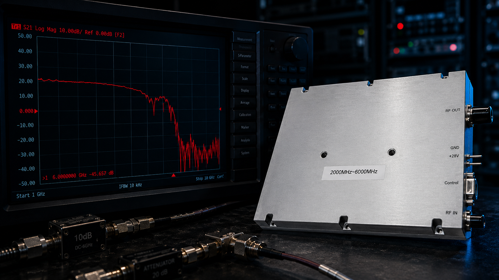
Antenna Over-The-Air (OTA) chambers present severe measurement challenges when uncalibrated series attenuators distort baseline reference planes. Here’s the deal: Engineers often cascade generic pads blindly within test setups. This practice introduces massive ripple across wideband frequency sweeps. Vector Network Analyzers (VNAs) will show severe S21 degradation near 6 GHz. Test operators incorrectly blame amplifier hardware for these erratic trace anomalies. The real issue stems from cascaded VSWR interactions between mismatched passive components. Reflected energy bounces backward. This creates standing waves that masquerade as poor module performance. I see this exact failure pattern weekly inside anechoic chambers. Hardware validation requires rigorous attention regarding calibration protocols across every RF path. You must de-embed all passive accessories before running high-power saturation sweeps. CorelixRF engineers always demand raw trace logs for proper root cause analysis. We analyze these logs looking for telltale ripple signatures. Inexperienced technicians frequently discard perfectly good radiating elements mistakenly. They assume antenna feed points have failed structurally. True engineering reality dictates questioning your test fixtures first. Mismatched passive components alter characteristic impedances dynamically during sweeps. This alteration ruins your entire measurement reference plane instantly.
Frequency and Power Specifications
| Parameter | Details |
| Frequency Range | 2,000-6,000 MHz |
| Output Power | 50 W |
| Gain | 46-48 dB |
2. What causes network analyzer trace collapse at high frequencies?
What’s the real story? High-frequency signal delivery demands pristine matching networks from your bench source directly towards any radiating element. An uncalibrated attenuator acts like an uncontrolled impedance bump near 6000 MHz. Test engineers observe immediate VNA curve collapses during upper band frequency sweeps. This happens because low-grade pads exhibit parasitic capacitance across internal resistive traces. That parasitic reactance dominates circuit behavior above 4 GHz. Your expected linear attenuation profile suddenly becomes a wildly reactive low-pass filter. This reactive shift ruins system link budgets entirely. You cannot trust automated power sweep data when passive components drift unrecognizably. A mischaracterized 10 dB pad might actually present 14 dB of insertion loss at upper frequencies. Such hidden losses force technicians into pushing drive levels dangerously high. This cascaded error chain eventually triggers thermal overload alarms on expensive transmission gear. Laboratory managers then face weeks investigating phantom hardware failures. We constantly remind integration teams about parasitic capacitance limits. High-frequency RF energy naturally seeks ground through any available dielectric medium. Cheap attenuators utilize poor dielectric substrates exhibiting massive loss tangents. This material choice guarantees signal degradation above S-band frequencies. Your instrumentation will display artificially high reflection coefficients constantly. You cannot compensate for this using simple mathematical offsets. The physical reality of your test setup has fundamentally changed.
3. Why do cascaded pads fail under continuous wave saturation?
Continuous Wave (CW) testing mercilessly exposes thermal weaknesses hiding inside cheap attenuator networks. Ready for the good part? Standard commercial pads lack adequate heat dissipation structures for prolonged 50 Watt exposure. The resistive film inside these components heats up rapidly under sustained RF drive. This localized heating changes bulk resistance values dynamically during active transmission cycles. A perfectly flat S21 calibration curve taken at milliwatt levels becomes completely invalid. As internal temperatures rise uncontrollably your attenuation factor drifts several decibels. We track these thermal shifts using fast infrared logging equipment on active test benches. The data consistently shows severe performance degradation within minutes of CW application. You must utilize specialized high-power terminations featuring massive heatsinks. Relying on generic lab accessories guarantees skewed validation results across wide bandwidths. Your final system performance reports will contain massive inaccuracies. We often see prototype radar modules fail field trials because of this exact testing flaw. The initial laboratory data looked perfectly acceptable under low drive conditions. Field deployment instantly exposed the hidden thermal drift issues. You must specify power ratings far exceeding your continuous wave output levels. Derating passive components guarantees absolute thermal stability during multi-hour test regimens. Professional RF engineers never compromise regarding test bench hardware quality.
Protection and Cooling Specifications
| Protection Feature | Specification |
| Input VSWR | $\le1.8$:1 |
| Output VSWR | $\le2.0$:1 |
| Cooling Method | Air Cooling |
4. How does thermal drift in passive components affect S21?
S21 measurements represent forward transmission characteristics which rely heavily on stable load conditions. This is where it gets interesting… An overheating series attenuator changes its characteristic impedance rapidly. This fluctuating impedance creates a moving target for any driving power amplifier. The resulting impedance mismatch sends significant reflected power backward through your transmission lines. We see this manifested as rapid S11 degradation on real-time spectrum analyzers. Reflected energy forces driver stages into non-linear operational zones unexpectedly. Test data recorded under these conditions reflects system instability rather than true Device Under Test (DUT) performance. You will log artificially compressed saturation points during these compromised automated sweeps. Engineering teams often waste weeks redesigning matching networks based on flawed data. Accurate measurement requires components that maintain strict thermal equilibrium under maximum rated loads. You cannot extrapolate high-power behavior from small-signal S-parameter files. The physics governing semiconductor junctions changes drastically under thermal stress. Reflected power standing waves create intense localized heating along transmission lines. These hotspots degrade dielectric materials inside your coaxial cables over time. We frequently replace melted connectors caused by these exact invisible standing waves. This physical damage halts testing schedules and drains project budgets rapidly. Always verify your load match before activating continuous wave power stages.
5. What makes the CRF-PA-2G6G-50W a reliable solution here?
The CorelixRF CRF-PA-2G6G-50W provides unparalleled stability for demanding wideband testing scenarios. You might be wondering… This module delivers a continuous 50 W output power across 2,000-6,000 MHz. We engineered it specifically for radar and electronic warfare system integration. It features an exceptional typical gain of 47 dB. This hardware maintains a strict gain flatness of 1.8 dB across its entire operating band. Such tight tolerances prevent baseline drift even when external passive accessories begin acting erratically. The unit draws a maximum current consumption of 12 A. It accepts a wide supply voltage range from 40 VDC up through 58 VDC. Our robust internal architecture handles input VSWR up to 1.8:1 without triggering false alarms. This physical resilience makes it perfect for field troubleshooting inside unpredictable OTA environments. We utilized advanced high-frequency laminate materials during PCB layout. These materials minimize insertion loss within our internal matching networks. You get maximum power transfer efficiency directly towards your radiating load. Our factory calibration process verifies every single unit under harsh saturation conditions. We never ship hardware displaying abnormal gain variations. System integrators receive fully characterized modules ready for immediate deployment. This strict quality control eliminates guesswork during your critical project phases.
Electrical Parameters
| Electrical Parameter | Value |
| Supply Voltage | 40-58 VDC |
| Current Consumption | $\le12$ A |
| Harmonics | $\le-10$ dBc |
6. How does factory VSWR protection secure your test bench?
Mismatched loads pose severe existential threats for any active microwave transmission hardware. But wait, there is more. The CRF-PA-2G6G-50W features integrated VSWR monitoring circuits that react instantly. Our output architecture tolerates an output VSWR of 2.0 :1 safely. If an uncalibrated attenuator suddenly fails open this amplifier actively protects its final stages. A generic module would likely suffer immediate catastrophic transistor failure under similar conditions. Our engineering team designed these protection loops using high-speed directional couplers. These internal sensors detect reflected power spikes within nanoseconds. We prioritize hardware survival because field replacements cost valuable testing time. You can rely on this ruggedness when connecting unknown antennas or experimental radiating structures. The 1.4 kg chassis acts as a massive thermal reservoir during these stress events. This robust design philosophy reflects our deep commitment regarding true engineering reality. We implement redundant thermal monitoring alongside fast VSWR protection. High-power amplifiers generate significant heat requiring massive aluminum enclosures. You must guarantee adequate airflow across external cooling fins continuously. Our internal telemetry allows remote monitoring during enclosed chamber operations. Operators can track module health without entering active radiation zones. This capability enhances personnel safety during high-power electronic warfare simulations. We build gear designed specifically for surviving brutal field conditions daily.
7. Why does wideband gain flatness matter for radar integration?
Modern radar systems utilize complex frequency hopping algorithms requiring absolute amplitude consistency. Let me explain. A non-linear gain profile distorts transmitted pulse shapes severely. When gain flatness exceeds specified limits your system cannot accurately resolve target signatures. The CRF-PA-2G6G-50W guarantees 1.8 dB flatness which keeps pulse envelopes pristine. We verified this performance using rigorous swept measurements showing typical S21 logs. Uncalibrated attenuators artificially inject ripple that simulates a failing output stage. Radar receivers interpret this amplitude modulation as false target velocities. Integrators must remove every parasitic variable from their transmission paths entirely. Using our tightly controlled amplifier establishes a reliable baseline for complex system calibration. You isolate external hardware faults faster when your core power block behaves predictably. True wideband performance demands component synergy from DC bias through RF output. Our engineers spend months optimizing inter-stage matching networks precisely. We eliminate parasitic resonances that typically plague multi-octave amplifier designs. You will not find sudden gain drop-outs hidden within our specified frequency range. Radar technicians appreciate this predictability when writing custom control software. Stable hardware allows software teams to focus solely on algorithm optimization. The entire system development cycle accelerates significantly. Reliable RF power blocks form the foundation of any successful microwave project.
Mechanical Specifications
| Mechanical Parameter | Details |
| Dimensions | $200\times158\times25~mm$ |
| Weight | $\le1.4$ kg |
| RF Input Connector | SMA-Female |
8. How can engineers verify true output power delivery?
Validating exact power levels requires bypassing suspect passive components altogether. Want to know a secret? We recommend coupling the CRF-PA-2G6G-50W directly towards a certified high-power calorimeter. This method eliminates frequency-dependent errors inherent in standard diode detector setups. You must supply a clean input drive level between -1 dBm and 6 dBm. This input range drives our internal stages into ideal saturated output states. Operators should monitor DC current consumption actively during these verification sweeps. A healthy module will draw predictable current up towards its 12 A limit. Any sudden current spikes indicate impedance discontinuities somewhere within your coaxial cabling. We always verify mechanical connections at the SMA-Female input and N-Female output ports. Proper torque application on these specific interfaces prevents intermittent contact issues during vibration testing. We supply precision torque wrenches specifically calibrated for RF connectors. Loose connections introduce massive phase noise into sensitive measurement equipment. You will see erratic power readings fluctuating wildly on digital displays. These fluctuations make peak power envelope calculations completely impossible. Direct calorimetric measurement removes these connection variables entirely from your dataset. You calculate absolute power based purely on thermal mass heating rates. This method represents absolute engineering truth regarding microwave power delivery.
9. What are effective steps for mapping link budgets accurately?
Systematic link budget analysis prevents cascading measurement errors from ruining project timelines. Here is the bottom line: You must characterize every single adapter using precision VNA calibration kits. We record exact insertion loss values for each component across all specific frequencies. The CRF-PA-2G6G-50W generates exceptional low spurious emissions measured at -60 dBc. It also maintains tight harmonic control at -10 dBc. These clean spectral characteristics make baseline system noise floor calculations much easier. You do not have excess out-of-band energy masking true device responses. Test engineers subtract verified passive losses from raw measured data confidently. This mathematical de-embedding reveals true antenna gain performance without hardware-induced artifacts. Proper mapping techniques transform unpredictable OTA chambers into reliable scientific instruments. Our technical support team reviews these specific integration details for customers within 48 hours. We help clients identify faulty passive components hiding inside complex schematics. You can request detailed S-parameter files characterizing our modules completely. These files allow precise simulation modeling before physical hardware procurement begins. System architects use this data predicting overall cascade noise figures accurately. We encourage open dialogue regarding your toughest field challenges. CorelixRF engineers thrive on solving seemingly impossible RF anomalies daily. Real-world physics dictates our straightforward approach toward every engineering problem.
Compliance and Quality Standards
| Compliance & Quality | Status |
| RoHS Compliant | Yes |
| CE / FCC | Yes |
| ISO 9001 / GJB 9001C | Certified |
10. How do you integrate CorelixRF modules into existing setups?
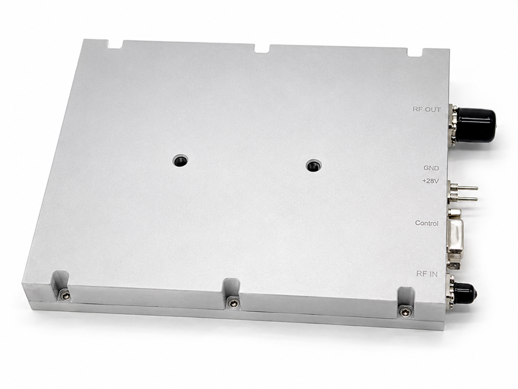
Mechanical and electrical compatibility determines how quickly replacement hardware restores operational status. It boils down to this: The CRF-PA-2G6G-50W features an accessible DB9 control interface. Its compact package size measures exactly 200\times158\times25~mm . This specific footprint allows seamless drop-in replacement inside crowded equipment racks. We design these units for extreme operating temperatures spanning -40 °C through +85 °C. Air cooling methods guarantee stable thermal performance during continuous duty cycles. You can secure the chassis easily using pre-drilled mounting holes shown on our mechanical outline. These mounting points keep mechanical stress away from fragile RF connectors. Our rigorous quality framework includes ISO 9001 and GJB 9001C compliance. This documented reliability makes integration approval straightforward for defense contractors. We maintain extensive component traceability records covering every production batch. You receive detailed test data reports accompanying each shipped amplifier. Our engineering team stands ready addressing any mechanical fitment concerns quickly. We regularly modify chassis dimensions accommodating unique client enclosure requirements. This flexibility guarantees your critical project deadlines remain intact always. You simply cannot afford delays caused by incompatible hardware form factors. CorelixRF delivers uncompromising performance wrapped inside highly adaptable physical packages.
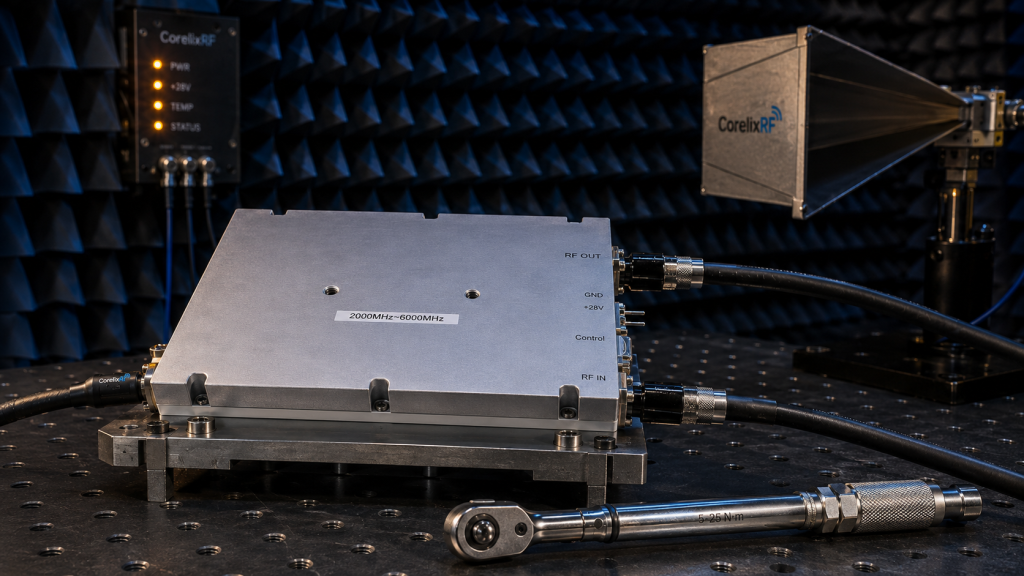
Uncalibrated attenuators routinely destroy measurement integrity inside complex testing environments. The CorelixRF CRF-PA-2G6G-50W eliminates these hardware-induced variables directly through robust internal architectures. You gain absolute confidence regarding your wideband data collection processes without second-guessing passive anomalies. Contact our engineering team immediately for rigorous technical support regarding this specific amplifier model.
FAQ Section
Q1: What is the frequency range for the CRF-PA-2G6G-50W? This module operates continuously across 2,000-6,000 MHz.
Q2: How does the CRF-PA-2G6G-50W handle mismatched loads? It tolerates an output VSWR of $\le2.0$:1 safely without catastrophic failure.
Q3: What is the maximum current consumption of this module? The unit draws a maximum current of $\le12$ A at full drive.
Q4: Does this amplifier support custom frequency bands? Yes, custom frequency bands and connectors are available upon request.
Q5: What cooling method does this power amplifier require? This system utilizes air cooling for continuous saturated output operation.
Turn this RF requirement into a quotable specification
Use this article as a starting point for a buildable RF specification. Before quoting, CorelixRF normally checks frequency range, output power, gain flatness, duty cycle, load mismatch, thermal path, control interface, enclosure limits and acceptance data.
- RF power amplifier platforms – match the article topic to available RF power amplifier families
- solid state power amplifier page – review SSPA architecture when reliability and repeatable test data matter
- custom amplifier support – request mechanical, control, cooling or frequency changes on a standard amplifier base
- RFQ checklist – send the data buyers usually forget, including band, power, duty cycle, interface and test standard
- delivery documentation – check what documents can support incoming inspection, FAT review and long-term maintenance
- case studies – review similar engineering paths before sending an RFQ
- engineering contact – send the application notes, block diagram or target specification to engineering sales
For a faster review, send operating band, power target, modulation or waveform, antenna/load condition, cooling limit, mechanical envelope and target test standard through the RFQ or contact path.