
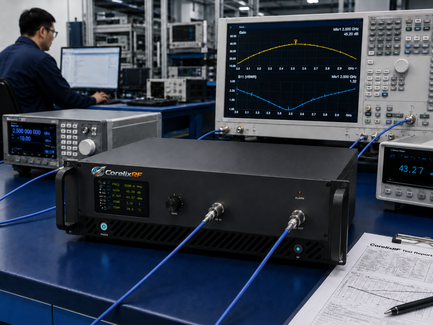
Testing millimeter-wave arrays inside anechoic chambers routinely exposes hardware vulnerabilities where engineers face inexplicable performance drops. You connect your device under test, expecting pristine measurements, only finding your vector network analyzer screen showing massive high-frequency roll-offs. But here’s the kicker those collapsing curves rarely stem from bad antenna elements themselves. Instead, fault frequently lies within upstream measurement chains where test engineers haphazardly stack components aiming at signal level control. Stacking uncalibrated attenuator pads creates compounded mismatch uncertainty directly destroying measurement integrity. We routinely observe these scenarios paralyzing radar development schedules. Resolving this demands rigorous architectural evaluation rather than applying temporary software offsets. Relying upon purpose-built amplification hardware, specifically the CorelixRF Wideband RF Power Amplifier CRF-PA-18000M40000M-20W, provides a scientifically sound methodology for eliminating cascaded loss variables.
1、 What Constitutes Catastrophic Failures in High-Frequency Antenna OTA Testing?
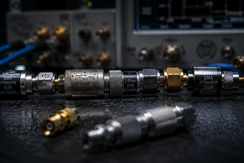
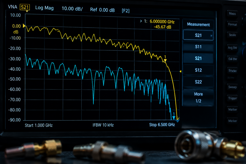
Catastrophic failure within Over-The-Air testing environments does not always manifest as smoke or localized melting. Far more insidious failure modes occur when measurement data looks plausible but contains severe, hidden inaccuracies caused by passive component drift. When evaluating phased arrays operating beyond Ku-band, engineers frequently insert passive attenuators between signal generators and amplification stages attempting precise input drive leveling. What’s the real story? These passive pads introduce massive error vectors because their individual VSWR profiles interact destructively. An uncalibrated 10 dB pad cascading into another 20 dB pad generates inter-component standing waves, completely destroying phase linearity. During swept-frequency tests, these standing waves create artificial ripples on your network analyzer screen. Test operators misinterpret these ripples as antenna gain variations, leading them down costly debugging paths modifying physical antenna geometries unnecessarily. Identifying physical mechanisms driving these artificial ripples requires analyzing reflection coefficients at every coaxial boundary layer.
| Parameter Issue | Physical Cause | Measurement Impact | System Result |
| Artificial Ripples | Inter-component standing waves | Distorted S21 curves | False antenna modifications |
| High-Frequency Roll-off | Uncalibrated pad insertion loss | Phantom gain compression | Failed compliance metrics |
| Phase Non-Linearity | Coaxial boundary reflections | Disrupted beamforming data | Inaccurate array calibration |
| Thermal Drift | Attenuator power dissipation | Unrepeatable sweeps | Wasted chamber testing time |
| Noise Floor Elevation | Pad thermal noise contribution | Decreased dynamic range | Hidden low-level sidelobes |
2、 How Do Cascaded Uncalibrated Attenuators Distort VNA Measurements in Millimeter-Wave Bands?
Understanding S-parameter distortion requires confronting raw microwave engineering physics head-on. When you cascade two discrete microwave components, you multiply their respective reflection coefficients.This is where it gets interesting passive attenuators inherently possess imperfect voltage standing wave ratios, which degrade significantly approaching 40 GHz. If an engineer cascades three uncalibrated pads, they effectively create a complex resonant cavity between those SMA or 2.92mm connectors. Energy bounces back and forth between mismatched interfaces, causing narrow-band nulls appearing randomly across your swept bandwidth. Because these pads lack rigorous recent calibration data, operators cannot mathematically de-embed these errors using standard VNA error correction models. The resulting test data becomes fundamentally compromised, masking actual device performance behind a wall of systemic architectural noise. Solving this requires removing discrete padding entirely.
3、 Why Is Component Selection a Trap in 18-40GHz RF Link Budgets?
Engineers drafting link budgets for electronic warfare testing rigs frequently underestimate connector transition losses. Selecting components spanning massive fractional bandwidths creates unique impedance matching nightmares. You might be wondering why simple coaxial adapters ruin months of array design. At frequencies approaching 40,000 MHz, microscopic variations inside connector dielectrics cause macroscopic impedance shifts. The CorelixRF CRF-PA-18000M40000M-20W mandates specific high-grade interfaces, utilizing a 2.92mm-F connector for input stages alongside a WRD180 waveguide for output delivery. Using cheap, off-the-shelf adapters immediately violates these precision boundaries. When engineers ignore these mechanical realities, they inadvertently build highly reflective bottlenecks. These bottlenecks force amplifiers into non-linear operating regions prematurely, degrading harmonic performance significantly. Furthermore, relying on theoretical datasheet values for cheap cables rather than measured insertion loss guarantees link budget failure before turning on main power supplies.
| Interface Component | Frequency Rating | Application Focus | Typical Failure Mode |
| SMA Connector | Sub 18 GHz | Legacy systems | Moding above 18 GHz |
| 2.92mm-F | Up to 40 GHz | Precision inputs | Pin damage from misalignment |
| WRD180 Waveguide | 18-40 GHz | High power output | Flange gap radiation leakage |
| Cheap Coaxial Cable | Variable | Budget test rigs | Phase shift with flexure |
| Uncalibrated Pad | Unknown | Quick fixes | Mismatch uncertainty compounding |
4 、How Does CorelixRF CRF-PA-18000M40000M-20W Resolve Upstream Architecture Bottlenecks?
Rather than relying upon external uncalibrated attenuators, modern test architectures demand amplifiers featuring deep internal gain control mechanisms. The CorelixRF module directly addresses this requirement by integrating an adjustable gain span reaching 15 dB. Ready for the good part? This internal adjustment capability allows engineers manipulating drive levels without breaking calibrated coaxial connections or inserting unreliable passive pads. Operating across a massive frequency range covering 18,000 – 40,000 MHz, this amplifier delivers a typical gain rating reaching 43 dB. By maintaining tight gain flatness bounded between -6 and 6 dB internally, it provides a highly predictable baseline for software normalization. This specific hardware architecture eliminates cascade mismatch uncertainty entirely. Test operators maintain unbroken, characterized transmission lines from signal generators directly into amplifier inputs, ensuring vector network analyzers measure actual device physics rather than test bench artifacts.
5、 What Are Thermal Dissipation and Frontend Matching Realities for 20W Ku-Ka Band PAs?
Generating twenty continuous watts at forty gigahertz demands extreme thermal management engineering. Gallium Nitride devices operating at these frequencies concentrate massive heat loads within microscopic semiconductor junctions. The CorelixRF amplifier consumes approximately 450 W of electrical power while generating its rated RF output. Here’s the deal: dissipating hundreds of watts of thermal energy dictates aggressive mechanical design parameters. The module utilizes specialized air cooling methods specifically engineered for sustaining zero-degree to fifty-degree Celsius operating temperatures. Housed within a standard 19-inch 3U package weighing 14.5 kg, the chassis acts as a highly optimized thermal sink. Upstream front-end matching networks must maintain strict input VSWR limits tightly controlled at 2:1, ensuring minimal power reflects back toward delicate signal generators. Without these rigorous thermal and matching frameworks, GaN lattices degrade rapidly under saturated continuous wave drive conditions.
| Parameter | Specification | Engineering Impact |
| Power Consumption | 450 W | Dictates facility power sizing |
| Cooling Method | Air cooling | Requires unobstructed rack airflow |
| Operating Temp | 0 to 50 °C | Enables field deployment flexibility |
| Dimensions | 19”, 3U | Fits standard integration racks |
| Weight | 14.5 kg | Necessitates robust rail mounts |
6 、How Does Active VSWR Protection Prevent Chamber Catastrophes?
High-power testing inside anechoic chambers inherently involves severe risk factors regarding accidental transmission line disconnections. If a technician accidentally severs a waveguide connection while transmitting twenty watts at thirty gigahertz, infinite VSWR reflects instantly back into final amplification stages. Let that sink in for a moment. Without sub-microsecond protection circuitry, that reflected energy permanently destroys expensive Gallium Nitride output transistors. The CRF-PA-18000M40000M-20W integrates comprehensive built-in protection mechanisms actively monitoring over-voltage, over-temperature, and over-current conditions. Furthermore, it offers optional over-drive protection, safeguarding internal stages against accidental signal generator programming errors. These active interlocks operate much faster than human reaction times or software polling loops. By measuring reverse power continuously, the architecture immediately shuts down bias voltages before reflected standing waves cause catastrophic lattice melting, thereby saving integrators from catastrophic equipment replacement costs.
7、 What Role Do Advanced Control Interfaces Play in Automated OTA Rigs?
Modern radar and electronic warfare verification requires thousands of automated test points executed sequentially without human intervention. Manual knob-turning simply cannot scale when characterizing complex phased array beam steering algorithms. This is where it gets interesting hardware must interface seamlessly with proprietary test executive software frameworks. The CorelixRF amplifier supports both RS485 and LAN control interfaces natively, providing robust digital pathways for remote telemetric monitoring. Integrators can further customize their modules selecting optional forward/reverse power monitoring, input power detection, and legacy GPIB control interfaces. These digital backbones allow scripting languages like Python or specialized environments like LabVIEW polling amplifier health status milliseconds before executing high-power sweeps. Such integration prevents executing test vectors while amplifiers remain outside thermal equilibrium, guaranteeing measurement repeatability across days of continuous chamber operation.
| Control Feature | Standard/Optional | System Level Benefit |
| RS485 Interface | Standard | Robust industrial serial networking |
| LAN Interface | Standard | Easy modern TCP/IP integration |
| GPIB Interface | Optional | Compatibility with legacy test racks |
| FWD/REV Power | Optional | Real-time VSWR monitoring capability |
| Input Detection | Optional | Prevents overdrive scenarios dynamically |
8 、How Can We Verify Output Power vs Frequency Under Saturated Conditions?
Analyzing final stage amplifier behavior requires looking beyond single-number specification sheet claims. Engineers must scrutinize performance curves defining saturated power across entire operating bandwidths. According to provided test condition parameters, measurements occur within strict 50 Omega systems unless otherwise specified. What’s the real story? The rated output power guarantees 20 W continuously. Typical saturated output power (Psat) characteristics demonstrate incredibly flat response curves from 18 to 40 GHz, hovering tightly around the 45 dBm threshold. Concurrently, P3dB curves track predictably below Psat, while P1dB linear limits remain clearly defined above 36 dBm across the entire band. Furthermore, harmonic content remains strictly suppressed below -10 dBc, and spurious emissions sit quietly below -60 dBc. This empirical data proves the GaN design holds linear integrity even when pushed near absolute maximum drive ratings.
9 、Why Is the System Integrator’s Perspective Vital for Final Quality Frameworks?
Purchasing raw hardware without evaluating its underlying quality framework introduces massive programmatic risk for defense contractors and tier-one telecommunication vendors. Amplifiers serving as cornerstone equipment inside aviation control testing must possess traceable manufacturing pedigrees. You might be wondering how factories prove their internal rigor. CorelixRF maintains a comprehensive compliance framework, ensuring their products meet stringent RoHS, CE, and FCC mandates. Beyond basic commercial certifications, they operate under strict ISO 9001 and military-grade GJB 9001C quality management systems. For rigorous project reviews, the factory supplies specific test data alongside precise pattern files where applicable, proving individual unit performance prior to shipment. This transparent data sharing allows system integrators mathematically budgeting exact performance margins before the physical hardware ever arrives at their loading docks.
| Certification | Industry Focus | Hardware Implication |
| RoHS Compliant | Environmental | Lead-free solder processes utilized |
| CE / FCC | Regulatory | Verified electromagnetic compatibility |
| ISO 9001 | Commercial Quality | Repeatable manufacturing procedures |
| GJB 9001C | Military Standard | High-reliability component traceability |
| Test Data Supply | Engineering Verification | Unit-specific performance mapping |
10 、What Are the Final Takeaways for Radar and EW System Integrators?
Eliminating cascaded uncalibrated attenuators from your OTA measurement chains constitutes an absolute requirement for securing accurate high-frequency data. Implementing architectures featuring internal adjustable gain, like the CorelixRF solution, removes compounded mismatch uncertainty mathematically and physically. Here’s the deal: continuing old habits using cheap passive pads above Ku-band guarantees flawed radar calibration tables. You must leverage specialized GaN hardware providing guaranteed flatness, robust VSWR protection, and verified saturated power curves across wideband spectrums. This specific hardware approach transforms unpredictable chamber environments into highly deterministic measurement laboratories. We strongly advise all test engineers currently battling phantom gain ripples reviewing their upstream amplification architecture immediately. Contact CorelixRF engineering support directly requesting unit-specific S-parameter files for conducting your own rigorous system-level mathematical evaluations.
FAQ
Q1: What is the specific frequency range and rated output power for the discussed amplifier? The CorelixRF CRF-PA-18000M40000M-20W operates across a frequency range spanning 18,000 – 40,000 MHz and delivers a rated output power reaching 20 W.
Q2: How does the amplifier connect to existing RF infrastructure mechanically? It utilizes a precision 2.92mm-F connector for input stages alongside a robust WRD180 waveguide for handling high-power output delivery.
Q3: What internal mechanism replaces the need for cascaded external attenuators? The amplifier features an internal adjustable gain mechanism providing up to 15 dB of control, allowing engineers to modify drive levels without breaking calibrated coaxial lines.
Q4: What built-in protection features secure the amplifier against common chamber accidents? The unit includes standard built-in protection against over-voltage, over-temperature, and over-current, alongside optional over-drive protection circuitry.
Q5: What remote control interfaces exist for automated test bench integration? The hardware natively supports both RS485 and LAN control interfaces, enabling seamless integration into automated test executive software environments.
Turn OTA RF-chain planning into an RFQ package
For 18-40 GHz OTA or antenna test chains, define the antenna type, amplifier power margin, cable loss, gain flatness, control interface, calibration method and required test curves before selecting hardware.
Recommended next step: send the operating band, output power target, duty cycle, load condition, control interface, grounding or thermal limits and required FAT documents. CorelixRF can review this 18-40 GHz antenna OTA RF chain requirement against standard RF amplifier platforms, RF front-end options and controlled customization paths.