
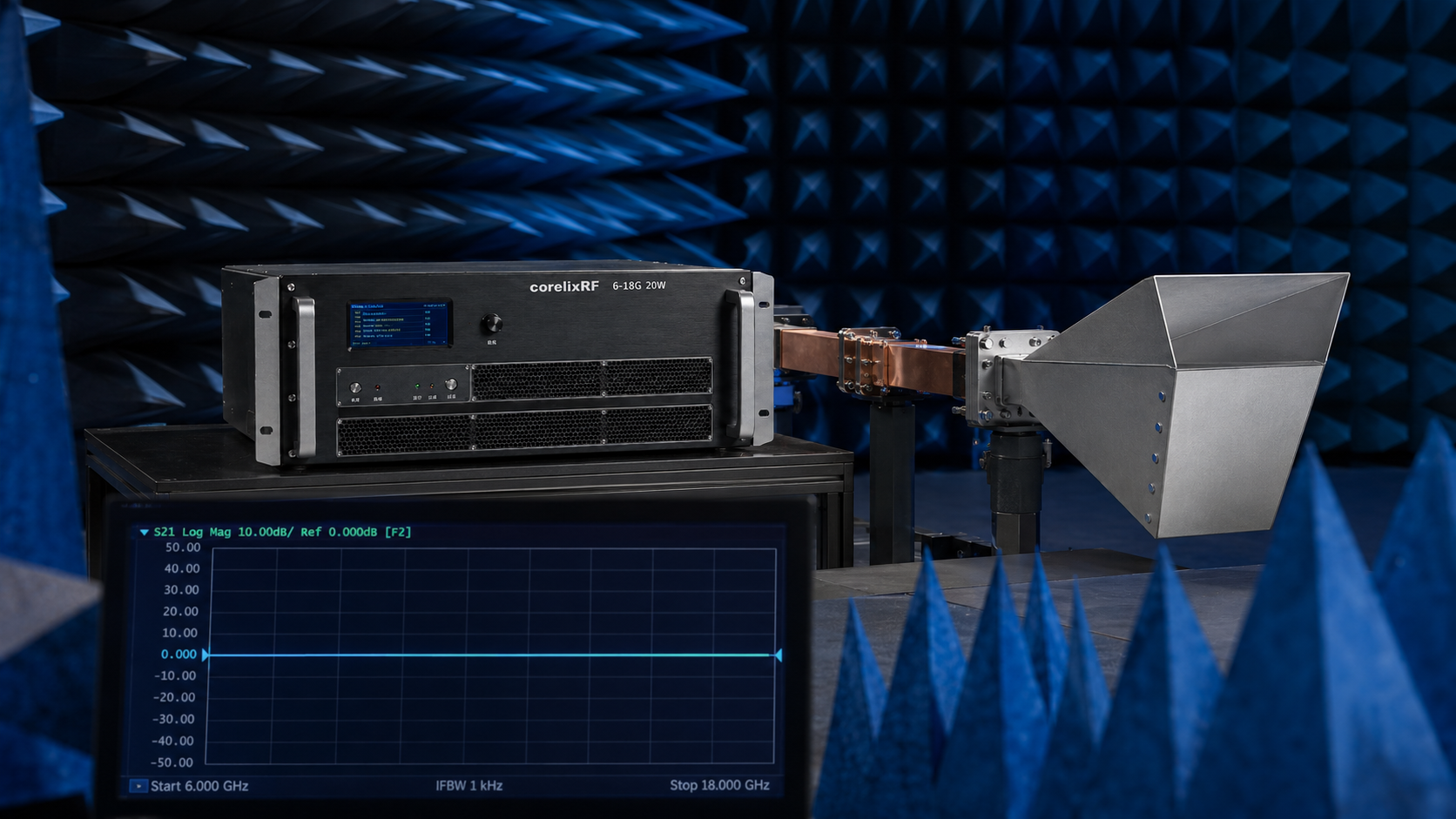
Engineers often face frustrating baseline shifts during anechoic chamber measurements. Applying rigorous network analyzer de-embedding solves most phase mismatch errors entirely. Our decades repairing broken microwave links guarantee factual engineering truth. We tackle physical hardware limitations head-on. Proper technique separates amateur setups from world-class laboratories completely. Expect hard data here.
1. What causes immediate gain flatness test data distortion inside anechoic chambers?
Chamber Environment Realities
Antenna over-the-air evaluations present unique microwave challenges constantly. Operators frequently string multiple pads together randomly. Here is the deal those cascaded components create severe impedance mismatches instantly. A single uncalibrated junction reflects energy back continuously. Standing waves form rapidly inside your shielded room. Operators watch high-frequency sweep plots collapse abruptly. We see cables draped across turntables constantly. Flexing those phase-stable cables alters return loss significantly. You must secure every physical connection properly. Loose SMA joints introduce intermittent parasitic capacitance quickly. Millimeter-wave bands penalize sloppy mechanical handling brutally. An operator might blame a device under test incorrectly. Bad test fixtures ruin perfect hardware runs easily. You need tight torque control always. Let me show a practical breakdown. Consider an aerospace radar module undergoing thermal cycling. Technicians added three different attenuators dropping signal levels safely. They ignored vector network analyzer recalibration entirely. Their resulting plots showed massive five decibel ripples. Removing one unnecessary adapter smoothed out their curve beautifully. Another case involved an automotive radar manufacturer experiencing similar chaos. They utilized cheap generic cables connecting expensive horn antennas. Simply swapping towards precision test port extensions fixed everything. Physical movement inside chambers guarantees dynamic baseline shifts constantly. Engineers must lock down every single variable aggressively preventing corrupted gain flatness test data.
Common OTA Failure Modes
| Symptom | Probable Source | Verification Method |
| Ripple above 30GHz | Mismatched attenuator pads | TDR step response |
| Sudden power drop | Damaged cable shielding | Flex testing |
| Baseline drift | Thermal variations | Calibrate immediately |
2. How do cascaded uncalibrated attenuators compromise millimeter-wave signal integrity?
Mismatch Penalties
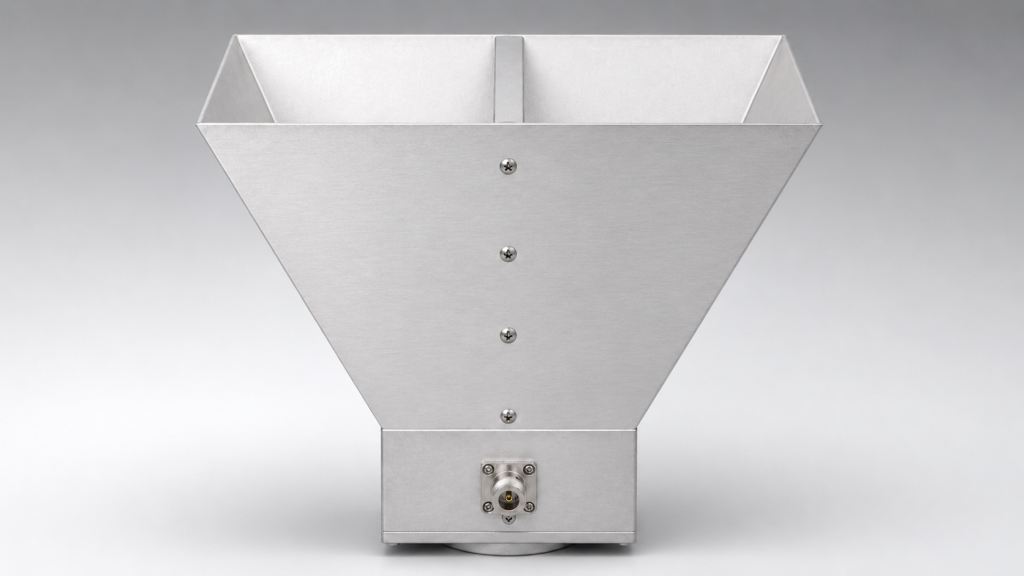
Engineers love stacking cheap pads for quick power reduction. You might be wondering why does chaining components destroy measurement accuracy? Each adapter introduces a distinct voltage standing wave ratio. Reflections bounce between imperfect transitions endlessly. These trapped waves add constructively or destructively at different frequencies. We call this phenomenon ripple. A user expecting flat response sees wild amplitude swings instead. Twenty gigahertz signals demand pristine transmission line continuity. Stacking a 3dB pad onto a 10dB pad multiplies your error margin exponentially. Precise calibration requires characterizing every single inline component beforehand. Neglecting this step invalidates any subsequent gain flatness test data. Your recorded measurements become utter garbage instantly. Professional labs rely upon single custom attenuators. They avoid random cascaded configurations completely. I recall auditing an electronic warfare integration facility recently. They chained four adapters mating a synthesizer into an amplifier. Their output spectrum looked like an angry sawtooth wave. We removed those unnecessary blocks entirely. We installed a single high-power directional coupler instead. Their signal flattened out remarkably fast. Uncalibrated blocks act like random microwave filters unpredictably. You lose absolute amplitude confidence immediately. Avoid cascaded setups whenever humanly possible. Physics dictates strict adherence regarding impedance matching networks. Small errors compound into massive system failures rapidly skewing your gain flatness test data.
3. Why does standard VNA calibration fail during complex OTA integration?
Calibration Plane Shifts
Vector network analyzers require exact reference planes. Consider this reality moving cables post-calibration destroys phase accuracy immediately. An engineer usually calibrates at a specific coaxial port. Then they connect a long feedline into a chamber. That extra electrical length remains completely mathematically unaccounted for. Temperature shifts alter phase velocity within dielectric materials. A warm laboratory behaves differently than an air-conditioned anechoic room. You must move your calibration plane directly towards a transmit horn. Electronic calibration modules help simplify this tedious process greatly. Always verify your setup using a known standard check. A flush short provides excellent verification confidence. Ignoring phase shifts guarantees faulty gain flatness test data entirely. We constantly find technicians neglecting basic reference plane extension commands. Proper metrology demands obsessive attention toward physical distances. One defense contractor wasted weeks debugging a phased array antenna. They calibrated their system outside their thermal vacuum chamber. Cooling that chamber shifted cable phase lengths dramatically. Their beamforming algorithms failed completely during cold soak testing. We implemented in-situ calibration routines solving their nightmare quickly. Dynamic environments require dynamic calibration strategies constantly. Never assume room temperature baselines hold true under stress. A secondary example involves satellite payload testing protocols. They relied upon factory calibration files blindly. Real-world cable bending shifted their null points completely. Re-calibrating onsite restored their measurement integrity perfectly securing their gain flatness test data.
Calibration Best Practices
| Action | Benefit | Frequency Impact |
| E-Cal near horn | Removes cable loss | High impact above 18GHz |
| Temperature soaking | Stabilizes dielectric | Affects phase angle |
| Torque wrench usage | Consistent mating | Eliminates random spikes |
4. What physical mechanisms drive high-frequency VSWR degradation anomalies?
Connector Tolerances
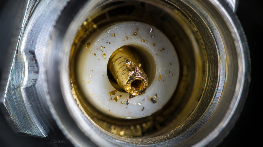
Mechanical dimensions dictate microwave performance absolutely. This is where things get interesting microscopic air gaps cause macroscopic reflection problems. A 2.92mm connector relies on precise pin depth. Overtightening damages a delicate center conductor permanently. Dirt particles disrupt uniform electromagnetic field propagation across junctions. We use microscopes inspecting failing test leads daily. A scratched dielectric interface creates unwanted parasitic inductance immediately. High frequencies compress wavelengths down millimeter scales. Any physical defect becomes a significant fraction of that wavelength. An uncalibrated attenuator might possess poor machining quality. Combining poor machining with cascaded setups spells absolute disaster. Electrons bounce off microscopic brass burrs chaotically. You cannot fix bad hardware through software smoothing tricks. A clean interface guarantees reliable signal flow. Let us examine a failed radar cross section facility. They experienced sudden dropouts around thirty-five gigahertz specifically. Microscope analysis revealed a smashed center pin inside one cable. An overly aggressive technician applied excessive mating torque blindly. Replacing that damaged lead restored their system instantly. Another incident involved tiny metal shavings trapped inside an adapter. Those shavings caused a massive resonant spike unpredictably ruining their gain flatness test data. Cleanliness ranks alongside electrical design regarding overall value. Your entire measurement chain acts like an intricate optical lens. Any smudge ruins your final picture entirely. Protect your connectors obsessively.
5. How can technicians identify hidden RF cable anomalies quickly?
Time Domain Analysis
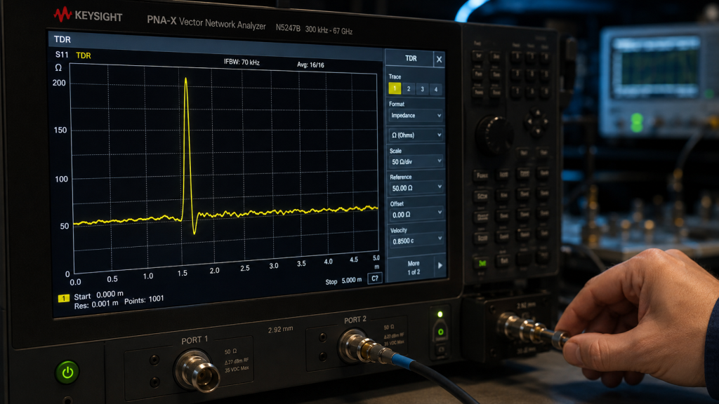
Locating faults requires switching into time domain mode. Ready for the good part? Modern network analyzers compute impulse responses beautifully. A frequency sweep tells you an error exists. Time domain reflectometry shows exactly where that error lives. You look for sharp impedance spikes along a graphical distance axis. A damaged connector appears as a massive inductive bump. Pinched cables show distinct capacitive dips clearly. We use this feature diagnosing complex OTA setups constantly. You simply measure physical distance along your feed network. Match that distance against your VNA screen display. This technique isolates uncalibrated attenuators instantly. Stop guessing which component failed during testing. Hard data removes human emotion from troubleshooting workflows. Measuring accurately saves hours of wasted diagnostic labor preserving gain flatness test data. I watched a junior engineer replace three expensive amplifiers unnecessarily. He assumed active components were failing under high thermal loads. I ran a quick step-response TDR measurement instead. We found a crushed coaxial segment buried under floor panels. We replaced that fifty-dollar cable fixing his multimillion-dollar setup. You must trust instruments over blind intuition always. Visualizing impedance over distance grants engineers incredible diagnostic superpowers. Never blindly swap expensive hardware without concrete evidence. Time domain plots provide that necessary forensic proof. Master this function thoroughly.
TDR Fault Signatures
| Display Anomaly | Physical Cause | Resolution |
| Sharp positive peak | Inductive gap | Re-seat connector |
| Broad negative dip | Squeezed cable | Replace test lead |
| Multiple reflections | Cascaded attenuators | Use single pad |
6. What specific role does our CRF-PA-18000M40000M-20W play here?
Amplifier Integration
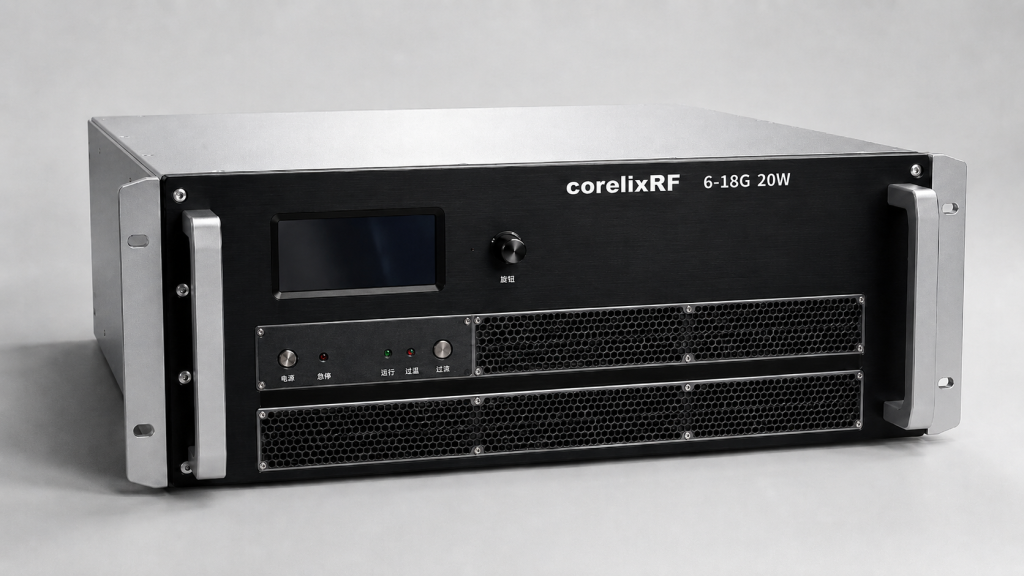
Overcoming chamber path loss requires substantial radio frequency muscle. What is the real story? The CorelixRF wideband power amplifier provides twenty watts continuously. We cover eighteen through forty gigahertz seamlessly. This unit guarantees a maximum gain flatness margin around plus minus six decibels. An input VSWR specified near two strictly minimizes mismatch interactions. You drive it using standard 2.92mm female connectors. Its output utilizes a rugged WRD180 waveguide flange. Built-in protection circuits monitor over-voltage conditions automatically. We prevent catastrophic failures during heavy mismatch scenarios. A nineteen inch rackmount chassis fits standard test racks perfectly. Users monitor parameters through RS485 or LAN interfaces easily. Excellent base flatness means your calibration routines work better generating precise gain flatness test data. Consider a drone detection system validation project currently underway. They struggled pushing enough power through long chamber feedlines. Our amplifier solved their link budget deficit immediately. We delivered clean wideband power across their entire swept spectrum. Another client needed reliable interference generation testing capabilities. They integrated our chassis driving a high-gain horn antenna. Our built-in protection survived multiple accidental open-circuit conditions safely. Good engineering anticipates human error gracefully. You need equipment surviving brutal laboratory realities daily. We design products specifically targeting these harsh environments.
7. How does advanced GaN technology prevent extreme power slumps?
Solid State Physics
Gallium Nitride transistors handle extreme thermal densities incredibly well. Think about that legacy technologies drop output significantly during prolonged operation. Our design relies entirely on advanced GaN technology architectures. High electron mobility yields superior high-frequency switching characteristics. Air cooling mechanisms dissipate four hundred fifty watts efficiently. You get stable continuous wave performance without liquid chilling requirements. An amplifier operating hot usually exhibits shifting S-parameters over time. GaN maintains stable transistor junctions across wide temperature ranges. Your gain flatness test data remains consistent throughout day-long evaluations. Our engineers matched internal stages specifically targeting broadband uniformity. You avoid replacing multiple narrow-band amplifiers during swept measurements entirely. This approach streamlines complex radar verification workflows beautifully. A telecom equipment manufacturer struggled with older traveling wave tubes. Their tubes drifted badly during extensive automated test sequences. They switched towards our solid-state GaN solution recently. Their data consistency improved dramatically overnight. Solid state reliability drastically reduces overall maintenance overhead costs. Another research laboratory replaced bulky klystrons using our compact rack. They reclaimed valuable floor space while gaining superior linearity. Modern semiconductors redefine what is physically possible today. Thermal management remains a necessary pillar supporting microwave power. We optimized airflow channels ensuring maximum heat extraction reliably.
CorelixRF Amplifier Parameters
| Parameter | Specification | Engineering Benefit |
| Frequency | 18,000 – 40,000 MHz | Covers Ku/K/Ka bands |
| Rated Output | 20 W | Overcomes chamber loss |
| Power Supply | AC 220V±10% | Direct grid connection |
8. What practical measurement steps verify accurate system flatness?
De-embedding Procedures
Obtaining true device performance demands stripping away fixture effects. Here is a secret you must measure your entire path separately first. Drive a known signal level from your network analyzer port. Record power received directly off a calibration antenna. Compare those numbers against theoretical free space path loss calculations. Any deviation represents your internal system baseline error perfectly. You apply this error correction file during final measurements. We highly recommend using independent thermal power sensors frequently. They offer better absolute amplitude accuracy than uncalibrated VNA receivers. Reconnect your cascaded attenuators only if absolutely necessary. Characterize their exact insertion loss across every test frequency beforehand. Quality engineering relies upon rigorous systematic verification protocols always. Your final gain flatness test data depends upon this discipline entirely. I helped an antenna manufacturer optimize their calibration routine once. They skipped measuring their intermediate test cables individually. I forced them into profiling every single RF segment separately. We uncovered a hidden resonance hiding inside a rotary joint. You cannot fix what you cannot see accurately. Systematic verification uncovers hidden demons lurking inside your racks. Build robust metrology habits early protecting your gain flatness test data. Trusting unverified test setups leads towards disastrous product launches. Secure your baselines using traceable power references.
9. How do WRD180 waveguide transitions impact total link budgets?
Waveguide Advantages
Pushing twenty watts through coaxial lines creates massive thermal challenges. Let that sink in standard cables melt under sustained millimeter-wave power. We utilize a WRD180 output interface mitigating this exact risk. Waveguides exhibit drastically lower insertion loss compared against coax. They handle extreme electromagnetic fields without suffering dielectric breakdown. An engineer gains precious decibels routing energy towards transmission antennas. You eliminate fragile pin connections completely at high power junctions. Flanges bolt together forming virtually seamless conductive channels securely. This rigid structure eliminates phase variations caused by cable flexing. Your cascaded networks become far more stable mechanically. Accurate gain flatness test data requires absolute mechanical stability always. Transitioning into waveguide solves multiple reliability headaches simultaneously. A military contractor melted several expensive coaxial cables previously. They tried pushing continuous power during a burn-in test. We upgraded their output routing utilizing standard rigid waveguides. Their thermal issues vanished completely. A university lab struggled maintaining phase stability across flexible leads. Upgrading their primary feed towards WRD180 stabilized their holography measurements. Metal pipes simply outperform flexible cables regarding high-power transmission. We engineer solutions matching actual physical constraints realistically. Respect high-frequency power dynamics actively. Appropriate transmission media guarantees operator safety alongside data integrity.
Transmission Line Comparison
| Media Type | Power Handling | Typical Loss |
| 2.92mm Coax | Low | High above 30GHz |
| WRD180 Waveguide | Extremely High | Very Low |
| Semi-rigid Coax | Medium | Moderate |
10. What maintenance protocols keep OTA test setups functioning flawlessly?
Preventative Care
Microwave laboratories require surgical cleanliness maintaining peak performance levels. Why does this matter? Dust ruins expensive test equipment rapidly. You must cap every unused connector immediately following tests. Clean interfaces using pure isopropyl alcohol and lint-free swabs regularly. Inspect mating surfaces via magnification spotting microscopic damage early. Never rotate a connector body during tightening sequences ever. Spin only a coupling nut preventing center pin scoring. Calibrate torque wrenches annually ensuring precise mechanical force application. Document all cascaded attenuator insertion losses in secure logbooks. Any sudden change indicates impending component failure clearly. We stress strict adherence towards metrology standards constantly. Proper maintenance guarantees your gain flatness test data remains unquestionable always. Consistent procedures separate amateur setups from world-class laboratories completely. We visited a struggling commercial compliance testing facility recently. Their engineers lacked basic connector care training completely. Their primary VNA ports showed severe mechanical degradation upon inspection. We instituted mandatory cleaning protocols saving their remaining equipment. Another group implemented automated verification checks before every shift. Their equipment uptime increased dramatically following that policy change. Discipline equals reliability regarding complex high-frequency testing environments. Treat your laboratory gear like delicate scientific instruments always. An ounce of prevention prevents weeks of painful troubleshooting later. Protect your hardware investments aggressively.
Uncalibrated cascaded components ruin microwave measurements quickly. Our robust 20W amplifier eliminates systemic power deficiency easily. Proper technique guarantees completely accurate OTA baseline characterizations always. Please contact CorelixRF securing a detailed product evaluation today. Superior hardware brings ultimate peace back into your laboratory. Review attached specifications planning your next chamber upgrade. Do not ignore basic physics.
Q1: What causes immediate gain flatness test data distortion?
Cascaded attenuators introduce severe impedance mismatches creating standing waves rapidly.
Q2: How do uncalibrated cascaded attenuators work against accuracy?
They multiply error margins through uncontrolled phase shifts and reflections.
Q3: Why does VNA calibration fail inside chambers?
Physical cable movement alters electrical lengths destroying reference plane accuracy completely.
Q4: What role does the CRF-PA-18000M40000M-20W play?
This amplifier provides stable twenty-watt output overcoming high frequency path losses effectively.
Q5: How does GaN technology prevent power slumps?
Gallium Nitride handles extreme thermal densities maintaining stable transistor junctions consistently.
Review antenna, amplifier and RF front-end as one chain
Antenna and OTA issues usually depend on antenna type, cable loss, amplifier margin, gain flatness, load condition, calibration method and required test curves. Put these details into the RFQ before selecting hardware.
Recommended next step: send the operating band, output power target, duty cycle, load condition, control interface, protection or thermal limits and required FAT documents. CorelixRF can review this How to Secure OTA Gain Flatness Test Data at 40GHz? requirement against standard RF amplifier platforms, RF front-end options and controlled customization paths.