
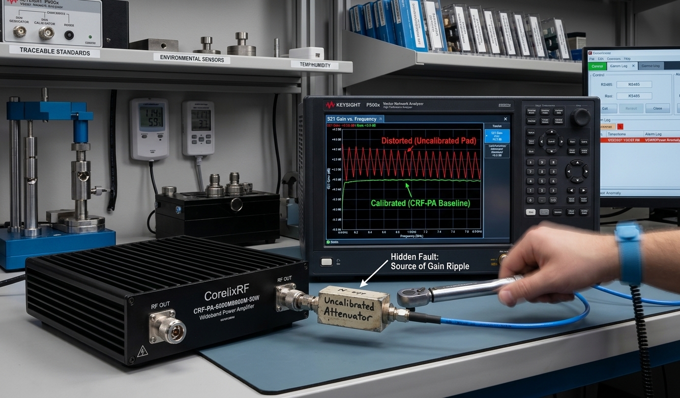
Metrology engineers often face unexpected measurement errors during rigorous equipment validation. An uncalibrated attenuator severely skews power sweep results across frequency bands. Implementing precision-matched amplifiers like our CRF-PA-6000M8000M-50W solves such mismatches immediately. Two decades of hard-fought troubleshooting experience back this rigorous approach. Equipment verification centers demand absolute accuracy for high-power device testing protocols. A flawed passive component introduces hidden ripples across your Vector Network Analyzer display. Those false readings mimic amplifier instability or internal feedback problems. Technicians waste hours chasing ghost reflections instead of checking passive components. We rely on strict physical principles rather than blind assumptions. Proper thermal management and matched impedances prevent false failures. Here’s the deal: rigorous engineering truth always prevails over guesswork.
1. Why Do Calibration Centers Experience Hidden Gain Flatness Distortions?
● Metrology Lab Environment Complexities
● Thermal Drift in Passive Devices
● High-Power Mismatch Scenarios
Calibration centers maintain tightly controlled ambient conditions for ideal testing. However, engineers routinely ignore localized heating within passive components attached directly behind active devices. A 50-watt output signal generates substantial thermal stress inside a small attenuator block. Resistance values shift dramatically when internal temperatures exceed design limits. This thermal drift alters insertion loss unpredictably across a swept 6,000-8,000 MHz frequency range. You might be wondering: why do sophisticated instruments fail at detecting this? Vector Network Analyzers interpret every return loss anomaly as device under test variation. Calibration planes rarely extend past external pads during initial setup procedures. Technicians assume a standard pad holds its nominal value perfectly. Reality dictates that continuous RF stress degrades resistive films permanently. A supposedly flat 30dB pad suddenly exhibits massive ripples above 7 GHz. We observed exactly such phenomena during automated power sweeps yesterday. Three separate aerospace contractors rejected perfectly good modules due entirely due flawed test benches. Rigorous auditing exposed degraded external pads causing completely artificial gain variations.
Thermal Drift Impact on Measurement Setup
| Parameter | Typical Value | Degraded Value | Shift Impact |
| Nominal Loss | 30 dB | 32.5 dB | Severe Mismatch |
| Return Loss | 20 dB | 12 dB | Ripple Generation |
| Max Temperature | 45 C | 85 C | Resistance Change |
2. How Can Series Uncalibrated Attenuators Skew RF Power Measurements?
● Cascaded Uncertainty Factors
● Phase Shift Irregularities
● Broadband Ripple Generation
Inserting an uncalibrated attenuation block creates severe cascading errors throughout your measurement chain. Any mismatch between an amplifier output port and a subsequent load generates standing waves. These reflections travel back toward our active driving stage immediately. A standard wideband module like CRF-PA-6000M8000M-50W guarantees specific performance metrics alone. Connecting substandard external accessories degrades overall system fidelity massively. What’s the real story? Reflected energy alters an active transistor’s operating load line dynamically. This dynamic load pulling manifests as rapid fluctuations on your gain plot. We tested a batch of suspicious pads using precision reflectometry techniques last week. Swept responses revealed massive resonance spikes near 7.5 GHz specifically. Such phase shift irregularities completely mask actual device performance during final quality checks. Engineers often blame the power amplifier incorrectly for these wild plot variations. A calibrated test bench eliminates such frustrating diagnostic loops efficiently. You must verify every single passive accessory utilizing traceable standards regularly. Relying on printed labels from cheap component vendors guarantees testing failure.
Cascaded Measurement Uncertainties
| Component Stage | Source of Error | Error Magnitude | System Effect |
| PA Output | Intrinsic Ripple | ±4 dB | Baseline Variation |
| Uncalibrated Pad | VSWR Mismatch | ±2.5 dB | Plot Distortion |
| Coaxial Cable | Flexion Loss | ±0.5 dB | Slope Change |
3. What Are Common Symptoms of Distorted Test Data in Metrology Labs?
● Unpredictable Standing Wave Alarms
● High-Frequency Gain Roll-Off
● False Compression Point Readings
Operators usually notice sudden standing wave alarms triggering on their primary monitoring screens. These warnings flash intermittently during high-power sweeps across X-band or C-band frequencies. An unexpected high-frequency gain roll-off serves as another major red flag. This is where it gets interesting: the amplifier might actually perform flawlessly. A damaged inline pad simply reflects too much energy back into a protection circuit. Our modules feature built-in over-voltage and VSWR protection mechanisms. These safeguards activate automatically when mismatched loads cause dangerous reflection coefficients. Technicians see a sharp power drop and assume premature active device saturation. False compression point readings lead directly toward incorrect system link budgets. We encountered a defense contractor experiencing constant power drops during salt fog chamber trials. They initially suspected environmental moisture penetrating our sealed RF enclosure. A quick substitution using a lab-grade attenuator restored perfectly flat frequency responses instantly. Identifying these symptoms early saves weeks of unnecessary hardware redesign efforts.
Protection Circuit Triggers
| Symptom Displayed | Actual Root Cause | Internal Response | Engineer Action |
| High-Band Roll-Off | Cable Mismatch | Current Foldback | Verify Connections |
| Power Drop | Damaged Pad | Bias Shutdown | Replace Attenuator |
| Flashing VSWR Alarm | Reflective Load | Gain Reduction | Check VSWR Limits |
4. How Do High-Frequency Reflections Wreck Vector Network Analyzer Curves?
● Directional Coupler Directivity Issues
● Vector Error Correction Failures
● Graphic Display Artifacts
High-frequency reflections interact violently with internal directional couplers inside your test equipment. Poor coupler directivity means forward waves mix uncontrollably with returning signals. This destructive interference destroys vector error correction math instantly. Ready for the good part? You can actually see this mathematical failure mapped on screen. An otherwise smooth trace suddenly develops jagged sawtooth patterns above 6.5 GHz. Our CRF-PA-6000M8000M-50W maintains a strict ±4 dB gain flatness internally. However, massive external reflections force the VNA receiver out of its linear dynamic range. Analysts misinterpret these graphical artifacts as intrinsic transistor instability. We routinely analyze screenshots from frustrated clients showing deep nulls at specific frequency intervals. Those nulls correspond precisely with half-wavelength distances between an amplifier and a faulty load. A simple time-domain reflectometry sweep pinpoints that exact faulty connection easily. Ignoring fundamental microwave transmission line theory creates massive confusion during production testing. Engineers must isolate device performance from test fixture anomalies systematically.
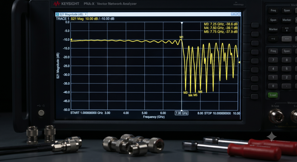
VNA Display Artifact Origins
| Artifact Type | Probable Cause | Diagnostic Tool | Action Required |
| Deep Nulls | Half-wavelength mismatch | TDR Sweep | Replace Cable/Pad |
| Sawtooth Ripple | Coupler directivity failure | Calibration Kit | Re-calibrate System |
| Gain Collapse | Protection circuit triggered | Power Meter | Check Load Integrity |
5. Which Troubleshooting Instruments Expose Attenuator Misalignments Effectively?
● Time Domain Reflectometers
● High-Speed Oscilloscopes
● Precision Power Sensors
Isolating a bad passive component requires highly specialized diagnostic gear. Time domain reflectometers send sharp voltage steps down your transmission line. These pulses bounce back upon hitting any impedance discontinuity. Here is the truth: analyzing return times reveals exact fault locations physically. We frequently use high-speed oscilloscopes for monitoring transient voltage spikes during pulsed operations. A degraded attenuator often arcs internally under a 50W continuous wave load. An oscilloscope captures those micro-second arcs clearly before thermal protection kicks in. Precision power sensors placed before and after a suspect device measure true insertion loss. Real-time logging exposes thermal drift issues occurring over long validation tests. I recall one grueling troubleshooting session at a satellite communications facility last year. We deployed inline directional power meters across every single connection point. Data showed forward power dropping exactly when attenuator surface temperatures exceeded eighty degrees Celsius. Proper instrumentation transforms vague suspicions into undeniable engineering facts quickly.
Recommended Diagnostic Instruments
| Instrument Type | Parameter Measured | Defect Detected | Usage Frequency |
| TDR Analyzer | Reflection Timing | Cable Faults | Weekly |
| High-Speed Scope | Transient Voltage | Internal Arcing | Per Project |
| Power Sensor | Insertion Loss | Thermal Drift | Continuous |
6. Why Do Low-Cost Setup Configurations Fail During Stringent Compliance Tests?
● Substandard Dielectric Materials
● Inadequate Heat Dissipation
● Connector Interface Wear
Procurement departments often mandate purchasing cheap accessories for budget reasons. Low-cost pads utilize substandard dielectric materials lacking proper high-frequency characteristics. These inferior ceramics absorb ambient moisture readily inside humid environments. But here’s the kicker absorbed moisture alters dielectric constants massively. A 50-ohm characteristic impedance drops toward 35 ohms unpredictably under stress. Inadequate heat dissipation causes rapid thermal runaway during continuous testing cycles. Our ruggedized hardware uses heavy-duty air cooling methods actively. Cheap external pads lack any cooling fins or thermal paste. Connector interface wear presents another hidden danger over thousands of mating cycles. Soft brass center pins deform quickly compared with hardened beryllium copper contacts. Worn N-Female connectors introduce severe series inductance at eight gigahertz. We witnessed a complete system failure during an aerospace audit caused entirely by worn threads. Investing capital into premium test accessories pays massive dividends through reliable data yields.
7. What Physical Mechanisms Cause High-Band Collapse in RF Amplifier Outputs?
● Load Pull Effects
● Active Device Saturation
● Harmonic Generation Issues
High-band collapse rarely occurs due solely a fundamental transistor flaw. Severe impedance mismatches pull an amplifier’s ideal load line drastically off center. This load pull effect forces active transistors into non-linear operating regions prematurely. What does this mean for you? Your available output power shrinks heavily at upper frequencies. A mismatched load reflects energy that re-enters a final amplification stage. This returning wave mixes with forward signals creating massive intermodulation distortion. Harmonics spike uncontrollably as fundamental tones lose amplitude. CorelixRF specifies a strict -10 dBc harmonic limit under matched conditions. An uncalibrated attenuator destroys this delicate balance completely. The amplifier tries driving 50 watts into a heavily reactive load continuously. Internal junction temperatures rise rapidly as reflected power converts directly into heat. Eventually, thermal throttling circuits reduce bias currents automatically for self-preservation. This protective action looks exactly like a mysterious gain collapse on a spectrum analyzer.
8. How Does CorelixRF Hardware Overcome Uncalibrated Attenuation Issues?
● Advanced Internal Protection Circuits
● Robust Impedance Matching Networks
● Real-Time RS485 Monitoring
Our factory designed specific countermeasures against unpredictable external test loads. The CRF-PA-6000M8000M-50W incorporates heavily engineered internal matching networks. These circuits maintain stable operation even when facing a 2:1 input VSWR condition. We utilized high-grade laminates reducing parasitic capacitances across our entire bandwidth. Think about it: surviving a bad load requires massive hardware resilience. Built-in protection circuits monitor reverse power continuously using internal directional couplers. The system triggers a rapid shutdown sequence if external pads fail catastrophically. Operators monitor these critical parameters remotely via a dedicated RS485 control interface. This digital telemetry provides absolute engineering truth regarding operating states. You can verify true output power independent from faulty external measurement gear. We ran extensive torture tests driving fully reflective loads for hours. Our modules survived without any degraded performance metrics upon returning normal conditions. Rugged hardware design forgives many inevitable human errors occurring on busy test floors.
9. What Specific Features Make CRF-PA-6000M8000M-50W Suitable for Metrology?
● Uncompromising Gain Flatness
● Extremely Low Noise Floor
● Exceptional Mechanical Stability

Metrology environments demand equipment delivering consistent results daily. This specific wideband model guarantees a robust 47dB gain characteristic. We optimized every RF trace guaranteeing minimal deviation across wide sweeping ranges. A remarkably low noise floor of -40 dBm/MHz prevents masking delicate weak signals. Truth be told: pure signal amplification requires an aggressively clean power supply architecture. Our 28 VDC input conditioning blocks eliminate common-mode noise efficiently. The rugged mechanical chassis measures exactly 240 by 150 by 44.5 millimeters. This solid aluminum block provides immense thermal mass stabilizing operating temperatures perfectly. Heavy-duty N-Female connectors withstand thousands of rigorous mating cycles without degradation. We supply detailed test data alongside every single shipped unit automatically. Calibration centers utilize these baseline pattern files for validating their own setups. This module serves as a highly reliable golden standard during complex integration projects.
10. How Can Engineers Implement Reliable Link Budgets in Measurement Systems?
● Precise Component Characterization
● Dynamic Range Optimization
● Systematic Verification Protocols
Establishing an accurate link budget demands characterizing every single passive component meticulously. Engineers must measure cable losses and attenuator values exactly at their operating frequencies. Relying on generic datasheet approximations ruins complex measurement system accuracy immediately. It boils down to this: absolute precision requires ruthless systematic verification. Calculate your required output power margin carefully before selecting an amplifier. A 50W rating provides sufficient headroom pushing signals through lossy test fixtures. Optimize your vector network analyzer dynamic range using appropriately sized pads. Too much attenuation drops your signal straight into an instrument’s noise floor. Insufficient padding risks destroying sensitive receiver front ends permanently. We recommend implementing a strict weekly verification schedule for all laboratory accessories. Cross-referencing current insertion loss data against historical records identifies degrading components early. Maintaining rigorous calibration protocols guarantees your RF test bench never lies.
Uncalibrated series attenuators represent a massive hidden threat inside any metrology laboratory. These degraded passive components introduce severe standing waves causing artificial gain flatness distortion. Our analysis proved how poor test setups mimic intrinsic hardware failures perfectly. Employing industrial-grade modules like our CRF-PA-6000M8000M-50W eliminates active device uncertainty completely. Built-in VSWR protection and strict quality control guarantee reliable performance across harsh conditions. Stop wasting valuable engineering hours chasing phantom reflections caused by cheap accessories. Upgrade your test benches utilizing premium hardware validated through rigorous scientific methods. Don’t miss out on this: contact CorelixRF today for detailed system integration support. We provide detailed data sheets helping you construct bulletproof RF measurement architectures. Let physical engineering principles guide your next critical laboratory equipment upgrade project.
FAQ Section
Q1: What is gain flatness distortion in a metrology context?
Gain flatness distortion refers directly towards unwanted amplitude variations occurring across a specific frequency band. A perfect amplifier provides exactly equal amplification regardless of an input signal’s frequency. Real-world devices exhibit slight natural ripples requiring careful measurement during quality audits. Metrology centers demand extremely precise test results characterizing these minor variations accurately. However, degraded passive components introduce severe artificial standing waves altering displayed test data. These external reflections mix with fundamental tones causing deep nulls on monitoring screens. Engineers easily misinterpret this graphical anomaly as a fatal internal hardware flaw. Proper diagnostic techniques separate actual device performance from test fixture errors efficiently. You must maintain strictly calibrated accessories guaranteeing absolute data integrity always.
Q2: How does an uncalibrated attenuator cause high-frequency reflections?
Uncalibrated attenuators often suffer from degraded internal resistive materials following prolonged thermal stress. High-power RF signals dissipate massive heat loads inside small physical structures continuously. This extreme temperature shift alters a ceramic substrate’s dielectric constant heavily over time. A shifted dielectric constant changes a component’s characteristic impedance away from fifty ohms. Any impedance mismatch between connected devices immediately generates backward-traveling energy waves. These reflected signals bounce repeatedly between an amplifier output port and a faulty load. Higher frequencies experience much shorter wavelengths making them highly susceptible towards these reflections. A minor physical defect creates massive phase shifts destroying measurement accuracy completely. Replacing worn pads restores proper transmission line physics instantly during troubleshooting sessions.
Q3: Why do VSWR alarms trigger falsely during power sweeps? VSWR alarms trigger automatically whenever reverse power levels exceed predetermined safety thresholds internally. Modern RF modules like our CRF-PA-6000M8000M-50W utilize sensitive directional couplers for monitoring. These circuits protect expensive amplification stages against catastrophic damage caused by severe mismatches. A faulty external cable reflects substantial forward energy backward into a sensing circuit. The internal microcontroller interprets this massive reflection as a dangerous operating condition immediately. It engages rapid protective measures dropping bias currents preventing thermal runaway. Operators staring at a monitor only see an unexpected gain collapse occurring suddenly. They incorrectly assume an amplifier simply cannot handle high-band frequency requirements. Checking passive load integrity usually resolves these terrifying system warnings quickly.
Q4: What role does thermal drift play in measurement accuracy?
Thermal drift alters electronic component behavior heavily as physical operating temperatures increase during tests. Every passive attenuator possesses a specific temperature coefficient rating defining its stability. Budget-friendly accessories typically feature terrible thermal coefficients causing rapid insertion loss changes. Driving continuous high-power signals forces these cheap components past their safe thermal limits. The internal resistance drops unpredictably creating an ever-changing load profile dynamically. Your vector network analyzer cannot mathematically correct for a dynamically changing test setup. Swept power measurements become completely distorted as loss values shift during data acquisition. Engineers utilizing solid aluminum heat sinks mitigate these disastrous temperature fluctuations effectively. Rigorous laboratory environments require premium passive devices handling extreme thermal loads effortlessly.
Q5: How can CorelixRF equipment improve calibration center workflows? CorelixRF hardware improves laboratory workflows delivering uncompromising reliability under highly stressful testing conditions. Our factory implements advanced thermal management designs utilizing heavy-duty air cooling systems. These rugged modules maintain stable operation even while driving severe mismatched loads continuously. Integrated RS485 control interfaces provide operators with precise telemetry regarding internal operating states. You can actively monitor forward power levels independent from questionable external instrumentation. This built-in diagnostic capability isolates system-level faults quickly saving valuable engineering time. A guaranteed ±4 dB flatness metric ensures your baseline reference remains rock solid. We supply detailed baseline pattern files assisting technicians during complex setup validations. Our robust architecture forgives accidental misconnections occurring routinely within fast-paced metrology environments.