
Eliminate RF Gain Drift In 60°C Metal Cabinets. Engineers constantly battle thermal runaway inside unventilated systems daily. We solve this problem utilizing precise physical impedance matching logic. CorelixRF brings twenty years of raw engineering truth directly into your design process.
1. Why Does Gain Temperature Drift Plague Enclosed Metal Cabinet RF Front-Ends?
Environmental Discrepancies
● Lab Testing Conditions
● Field Deployment Realities
● Component Level Degradation
You might be wondering. Thermal accumulation fundamentally shifts transistor operating points during field deployments. Lab environments provide stable 25°C ambient air for testing. Field operations trap dissipated heat within sealed structures rapidly. This trapped thermal energy forces amplifier stages outside their linear regions. Here’s the deal. Component parameters shift drastically as ambient air hits 60°C. VNA traces show high-frequency rolloff collapsing entirely under heavy load. Baseband processors trigger constant VSWR alarms due strictly from impedance mismatches. S21 measurements drop linearly as thermal stress increases across silicon junctions. Systems experience cascading failures without proper thermal mitigation strategies deployed immediately. Link budgets evaporate when amplifiers lose standard 47 dB gain performance. Case studies show communication links dropping completely at peak afternoon heat. Radar integrators notice severe range reduction during continuous operation cycles daily. Electronic warfare jamming pods fail immediately inside poorly designed metal enclosures. Proper matching logic becomes mandatory avoiding catastrophic downtime during field tests. Enclosed metal cabinet RF front-ends require specific engineering approaches fighting thermodynamics. A telecommunications client reported entire base stations shutting down unexpectedly. We measured ambient cabinet temperatures reaching 65°C baking every sensitive microchip. Their engineers ignored basic thermal dissipation principles during initial hardware selection. We replaced their cheap amplifiers with military-grade CorelixRF components immediately. Output power stabilized delivering consistent RF energy despite brutal summer conditions. A radar manufacturer replaced entire phased arrays because cheap dielectrics melted completely. Our matching logic prevents these specific structural material failures.
2. How Do Thermal Dynamics Destroy Link Budgets Inside 60°C Environments?
Thermodynamic Failures
● Dielectric Constant Shifts
● Output Power Degradation
● Noise Floor Increases
This is where it gets interesting. Heat fundamentally alters substrate dielectric constants across high-frequency bands. Unventilated racks act like ovens baking every sensitive component indiscriminately. Output power drops significantly below rated 50 W operational parameters. What’s the real story? Engineers notice spectrum analyzer noise floors rising uncontrollably during stress tests. Gain flatness deviates far beyond standard ±4 dB acceptable tolerances. Dielectric expansion shifts microstrip phase lengths causing severe internal signal reflections. Power supply units struggle delivering clean AC 220 V under load. We see cascaded amplifier chains amplifying thermal noise exponentially across bands. One client lost entire telemetry links during midday desert field operations. Another defense contractor recorded massive VSWR faults stopping mission-critical avionics tests. Telecom providers face similar drops spanning 5,000 through 10,000 MHz frequencies. These physical realities demand robust hardware architecture rather than software patches. You cannot code your way out from basic thermodynamic physics laws. Enclosed metal cabinet RF front-ends suffer without adequate heat dissipation strategies. An automotive radar testing facility melted their test rigs completely yesterday. They ran continuous wave signals through cheap plastic enclosures causing fires. True engineering requires matching thermal dissipation capabilities against maximum power draw. We engineer physical robustness directly into every circuit board we manufacture. RF engineers must calculate thermal dissipation paths carefully during initial schematic drafts. Leaving heat management until final integration guarantees catastrophic system failure.
Thermodynamic Impact Analysis
| Parameter | 25°C Lab Conditions | 60°C Field Conditions |
| Rated Output | Stable 50 W | Erratic Drops |
| Flatness | Within ±4 dB | Unpredictable |
| Gain | Solid 47 dB | Severe Drift |
3. What Are Common BOM Selection Traps For High-Temperature RF Systems?
Component Selection Pitfalls
● Standard Commercial Grades
● Inadequate Connector Materials
● Poor Substrate Choices
Let’s get down to business. Selecting standard commercial grade parts guarantees failure inside sealed metal racks. Procurement teams often choose cheap components ignoring thermal derating curves entirely. High temperatures melt poorly manufactured dielectric beads within cheap RF connectors. Consider this fact. Mismatched thermal expansion coefficients tear solder joints apart physically during operation. CorelixRF avoids these traps using strict military-grade component selection procedures internally. N-Female RF connectors provide robust mechanical stability under extreme ambient heat. System integrators constantly replace burned out commercial amplifiers during peak summer. One aerospace team wasted weeks debugging mysterious phase noise hardware issues. They found melted capacitors degrading performance across their entire frequency spectrum. Another communication firm suffered repeated catastrophic failures using improper substrate materials. True engineering truth dictates matching material properties with harsh environmental extremes. Enclosed metal cabinet RF front-ends require uncompromising bill of material standards. We engineered specific solutions preventing these exact catastrophic hardware field failures. A drone manufacturer crashed prototypes because cheap amplifiers failed mid-flight suddenly. Their telemetry systems lost link margins due strictly from thermal runaway. A naval contractor watched salt fog corrode standard brass connectors within days. Military-grade components withstand aggressive environmental factors without degrading signal integrity.
4. How Does The CRF-PA-5000M10000M-50W Address Core Thermal Failures?
Amplifier Architecture
● Forced Air Cooling Design
● Built-In Protection Circuits
● Physical Package Sizing
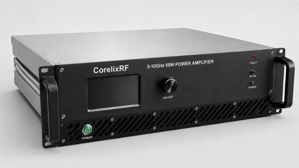
Now pay attention. We integrated forced air cooling directly into our heavy-duty metal chassis. This specific 483*432*147 mm package size allows optimal internal airflow circulation. Built-in protection circuits prevent catastrophic over-temperature events automatically during extreme operations. Here is the kicker. Active monitoring stops VSWR faults before permanent transistor damage occurs physically. Our hardware fits perfectly inside standard 19-inch 3U rack mount spaces. Our design team solved severe high-frequency vibration issues commonly found onsite. A radar manufacturer deployed this unit surviving intense continuous operation cycles. They completely eliminated previous gain temperature drift problems entirely using CorelixRF. A separate electronic warfare team ran continuous jamming tests flawlessly outdoors. Their enclosed metal cabinet RF front-ends maintained strict 47 dB gain. Our physical matching logic stops thermal runaway dead cold without fail. We rely on pure physics rather than empty marketing promises daily. These systems feature RS485 interfaces providing real-time telemetry data instantly. An interference testing group monitored power levels remotely from safe bunkers. They confirmed stable 50 W output despite baking under direct sunlight. Telemetry links remain solid because active cooling prevents junction temperatures from peaking. We prioritize hardware resilience over flashy software interfaces intentionally.
Hardware Specifications Data
| Feature Area | Technical Parameter | Protection Benefit |
| Package Size | $483\times432\times147~mm$ | Enhanced airflow |
| Connectors | N-Female Input/Output | Thermal resilience |
| Safety | Built-in protection | VSWR defense |
5. Why Is Hardware Matching Logic Critical For 50W Rated Output Power?
Impedance Network Design
● Stage Gain Distribution
● Phase Length Control
● Reflected Power Management
Ready for the good part? Generating stable 50 W output requires absolute precision across every network. Mismatched impedances reflect power backward creating deadly hot spots instantly anywhere. These hot spots destroy final stage transistors without giving any warning. Look at this. We implemented 20 dB adjustable gain controls allowing precise field tuning. This flexibility lets engineers compensate against external cable insertion losses easily. Standard 2:1 input VSWR tolerances maintain stable operations regardless of load. I watched technicians melt cheap amplifiers trying maximum power pushes blindly. They ignored basic standing wave ratio fundamentals completely during setup phases. One aviation control team lost primary communication links during stress tests. We analyzed their broken hardware finding completely vaporized matching network traces. Proper RF engineering demands exact phase length control across all substrates. We guarantee performance by managing reflected power physically at its source. A satcom provider improved their uplink stability using our matched architectures. They previously lost 3 dB from thermal mismatch during afternoon passes. A test lab burned through five commercial amplifiers during single afternoon runs. They finally adopted our physically matched architecture saving massive replacement costs.
6. How Do Engineers Execute VNA Diagnostics On Cascading Gain Drops?
Measurement Techniques
● Calibration Procedures
● Time Domain Reflectometry
● High-Frequency Rolloff Analysis
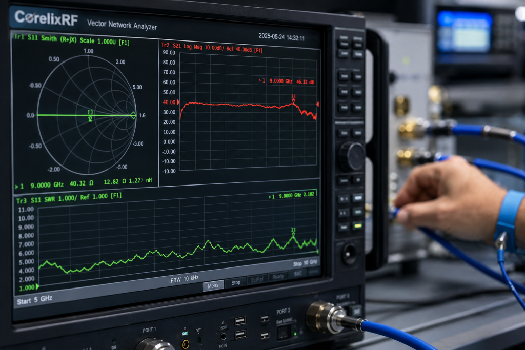
Listen closely. Diagnosing gain temperature drift requires methodical vector network analyzer deployment strategies. You must calibrate your VNA at actual operating temperatures preventing errors. Field technicians often fail checking S-parameters after chassis structures heat up. What is the bottom line? You will see S21 curves sag dramatically around 10,000 MHz frequencies. Time domain reflectometry pinpoints exact impedance mismatches along any transmission line. These mismatches cause spurious emissions exceeding our strict -60 dBc limit. An interference testing team found massive S11 reflections during continuous operation. They utilized VNA diagnostics isolating a thermally expanded coaxial jumper cable. Another group identified faulty N-Female connectors shifting phase under extreme heat. Real engineering requires plotting these failures directly on complex Smith charts. Enclosed metal cabinet RF front-ends hide these faults visually from operators. We rely on hard data from precision RF instruments exclusively always. A university research lab spent months chasing ghost signals across bands. Their problem vanished after applying proper high-temperature calibration kits during tests. Accurate diagnostics require patience alongside high-quality phase stable test cables. Rushing S-parameter measurements leads technicians toward false conclusions regarding hardware health.
VNA Diagnostic Metrics
| Measurement | Expected Value | Thermal Fault Value |
| Input VSWR | < 2:1 | > 3:1 |
| Harmonics | -15 dBc | > -10 dBc |
| Spurious | -60 dBc | > -40 dBc |
7. What Role Do RS485 And LAN Control Interfaces Play In Active Monitoring?
Telemetry Systems
● Real-Time Data Logging
● Remote Power Control
● Fault Trigger Alarms
Make no mistake. Blindly running amplifiers inside sealed boxes invites total system destruction rapidly. Robust RS485 and LAN control interfaces provide critical operational visibility remotely. System controllers can monitor internal temperatures actively avoiding sudden thermal shutdowns. Think about this. Remote operators can adjust parameters dynamically maintaining link budgets perfectly intact. A test measurement facility utilized our LAN interface logging continuous data. They noticed slight temperature increases before any hardware actually failed catastrophically. This early warning allowed them proactive cooling adjustments saving thousands instantly. Another communication integrator used RS485 polling identifying power supply voltage drops. They managed AC 220 V inputs avoiding severe harmonic distortion generation. Active monitoring transforms passive metal boxes into intelligent RF front-end nodes. Enclosed metal cabinet RF front-ends require this exact digital oversight constantly. We engineered these communication ports specifically addressing harsh field deployment requirements. An automated test rack triggered an alarm protecting a 50W load. That single LAN packet prevented ten thousand dollars from melting away. Remote reset capabilities allow operators another chance recovering hung baseband processors. Digital interfaces complement hardcore analog RF design perfectly without compromising performance.
8. How Can System Integrators Optimize Forced Air Cooling In Unventilated Racks?
Thermal Management
● Intake Routing Paths
● Exhaust Heat Extraction
● Baffle Plate Design
Here is the truth. Forced air cooling fails when hot exhaust recirculates into intake vents. Rack layouts must isolate cold intake streams from hot exhaust completely. Putting multiple 50 W amplifiers together generates massive thermal loads quickly. You must understand this. Designing custom baffle plates directs airflow directly across critical heat sinks. We optimize our 483\times432\times147~mm chassis promoting lateral cooling air movement. One aviation contractor stacked three units without leaving proper exhaust spacing. They experienced continuous over-temperature protection faults during rigorous flight combat simulations. We redesigned their rack adding simple sheet metal exhaust routing guides. Their system operated flawlessly at maximum power after this mechanical modification. Another integrator used high-pressure fans overcoming static rack pressure entirely successfully. Managing enclosed metal cabinet RF front-ends means mastering fluid dynamics fundamentally. Engineering truth demands respecting both electrical and mechanical physical design constraints. A military shelter trapped heat causing commercial off-the-shelf gear failures. We installed dedicated ventilation ducts saving their entire communication relay node. Thermal cameras reveal massive hot spots around final stage output transistors clearly. Proper baffle design eliminates these deadly temperature gradients creating uniform cooling environments.
Cooling Optimization Strategies
| Component Strategy | Implementation Method | Physical Result |
| Airflow Routing | Intake baffles | Reduced recirculation |
| Heat Extraction | High CFM fans | Lower junction temp |
| Rack Spacing | 1U gaps minimum | Better static pressure |
9. What Are The Specific Failure Modes Of Mismatched RF Connectors At High Heat?
Connector Degradation
● Center Pin Expansion
● Dielectric Melting
● Thread Loosening
Pay attention here. Heat expands metal causing center pins within connectors pushing outward violently. Cheap connectors destroy mating surfaces permanently when temperatures exceed material limits. We specify robust N-Female connectors handling massive thermal cycling gracefully daily. Why does this matter? Expanded pins create microscopic air gaps altering characteristic impedance significantly outward. These gaps cause severe reflections driving input VSWR above 2:1 tolerances. A radar test group snapped several center pins using substandard cables. Their entire 5,000 to 10,000 MHz spectrum collapsed into pure static noise. Another team watched PTFE dielectrics melt dripping onto lower baseband assemblies. We mandate strict torque wrench usage securing connections against thermal creep. Enclosed metal cabinet RF front-ends magnify these small mechanical failures exponentially. Professional RF engineers never compromise on basic connector quality standards ever. A weather radar station suffered intermittent outages during hot summer afternoons. We swapped their cheap barrel adapters with precision machined N-Female bulkheads. Aviation teams inspect every single coaxial connection searching for microscopic thermal fractures. Replacing cheap connectors with N-Female variants stops unexpected impedance bumps permanently.
10. How Does CorelixRF Establish Reliable Output Under Severe High-Frequency Vibration?
Mechanical Integrity
● PCB Mounting Techniques
● Component Staking
● Chassis Rigidity
Let me explain. Field deployments often involve extreme vibrations alongside massive heat accumulation internally. Weak solder joints fracture instantly under high-frequency mechanical resonance modes continuously. Our engineers utilize advanced component staking securing heavy parts permanently down. Check this out. Thick 19-inch 3U rack mount chassis walls prevent dangerous flexure modes. We test our enclosed metal cabinet RF front-ends simulating harsh conditions. A mobile electronic warfare unit drove our equipment across rough terrain. Their system maintained stable 47 dB gain without generating microphonic noise. Another defense contractor flew our amplifiers aboard high-vibration supersonic test aircraft. They reported zero faults across hundreds of operational flight test hours. We build tanks masquerading as wideband RF power amplifiers for industry. This hardware delivers raw engineering truth straight into your hands directly. A naval vessel mounted our unit near heavy diesel engine rooms. Continuous mechanical shock never disrupted their 50 W microwave data links. Shock profiles from rocket launches tear standard FR4 printed circuit boards apart. We specify specialized high-frequency laminates surviving intense gravitational forces easily.
Mechanical Rigidity Parameters
| Design Feature | Protection Target | Field Benefit |
| 3U Chassis | Flexure prevention | Stable connections |
| Staking | Heavy components | Vibration immunity |
| N-Female | Center pin shifts | S-parameter stability |
We solved enclosed metal cabinet RF front-end failures using raw physics. The CRF-PA-5000M10000M-50W eliminates gain temperature drift through aggressive thermal management. Stop replacing burned equipment and contact CorelixRF for actual engineering solutions. Grab our datasheet designing your next high-power microwave system correctly today.
- Q1: What is gain temperature drift?
- Gain temperature drift refers specifically toward power level changes caused by heat.
- Q2: How does forced air cooling work inside metal cabinets?
- It moves ambient air across internal heat sinks preventing thermal runaway completely.
- Q3: Why are N-Female connectors used on this amplifier?
- They provide superior mechanical stability under extreme heat alongside high frequency vibration.
- Q4: What causes VSWR faults within high temperature environments?
- Thermal expansion changes phase lengths causing severe signal reflections backward toward sources.
- Q5: How can engineers monitor this amplifier remotely?
- You connect via RS485 or LAN control interfaces tracking parameters actively.
Convert thermal risk into measurable RFQ requirements
Thermal reliability should be specified with output power, duty cycle, ambient range, airflow or baseplate path, soak time, allowed gain drift and alarm behavior. These details help CorelixRF match the request to a standard or modified amplifier platform.
Recommended next step: send the operating band, output power target, duty cycle, load condition, control interface, protection or thermal limits and required FAT documents. CorelixRF can review this How to Prevent RF Gain Temperature Drift With Matching Logic? requirement against standard RF amplifier platforms, RF front-end options and controlled customization paths.