
Primary engineering guide: this near-duplicate reference has been consolidated under How to Troubleshoot RF Gain Drift in High-Temperature Outdoor Cabinets?. Use the primary guide for the latest RF engineering review, compliance-safe wording, RFQ inputs and factory documentation path.
- Open the primary guide for the current topic cluster.
- Prepare RFQ inputs before requesting engineering review.
- Use the RF configurator to summarize band, power, interface and duty-cycle needs.
- Review delivery documentation for FAT-style evidence and shipment records.
- Contact CorelixRF when the project has a documented scope.
Archived page topic: How to Troubleshoot RF Amplifier Gain Drift in Sealed Cabinets?. This page remains available for reference, but search engines are pointed to the primary guide through canonical consolidation.
This article addresses RF output failures within enclosed rack systems. We analyze thermal variations causing performance degradation. Field technicians face severe troubleshooting challenges during integration. Our guide dissects physical mechanisms behind high-temperature anomalies. We provide practical diagnostic methodologies.
1. How Does Gain Drift Manifest in Sealed Metal Cabinets?
Spectral Anomaly Observation
Here is the deal. Field environments rarely match controlled factory conditions. System integrators frequently encounter frustrating spectral anomalies during final site deployment. You install an amplifier inside an unventilated equipment enclosure. Ambient air stops circulating naturally. Internal thermistors register severe spikes. RF output power plummets unexpectedly across your primary operating band. You watch spectrum analyzer traces collapse before your eyes. Signal saturation limits dynamic range severely. Radar screens display false targets due solely upon fluctuating amplitude levels.
● Output amplitude drops
● Noise floor raises
● System alarms trigger
Your built-in test equipment triggers continuous over-temperature warnings. This specific failure mode plagues electronic warfare jammers crammed tightly into armored vehicle bays. Stagnant ambient air prevents adequate convective transfer. Amplifier modules bake themselves into soft shutdown routines. We regularly observe output drops exceeding 3 dB under these trapped thermal conditions. Engineers must understand physical constraints governing sealed enclosures. Ignoring ambient temperature differences guarantees catastrophic mission failure. Field engineers waste countless hours replacing perfectly good hardware mistakenly. Diagnostics remain impossible without acknowledging severe localized heating mechanics.
Environmental Condition Variance
| Environmental Parameter | Laboratory Setting | Sealed Cabinet |
| Cooling Method | Open air convection | Stagnant trapped air |
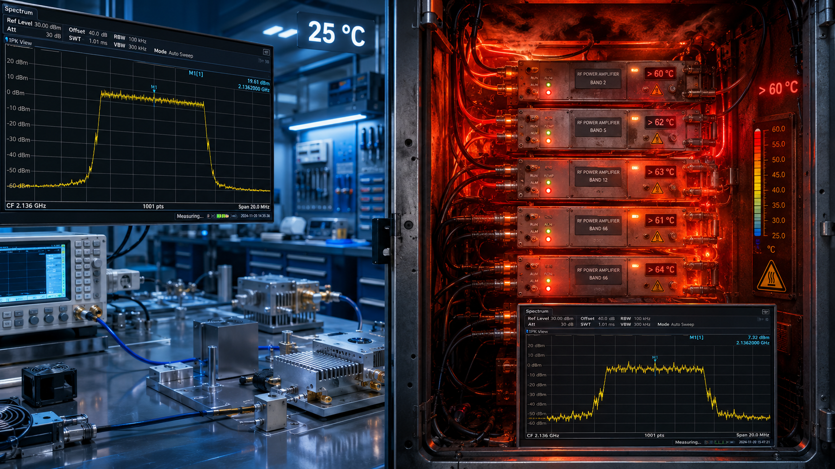
| Baseline Temperature | 25 degrees Celsius | 60 degrees Celsius |
| RF Output Stability | Perfectly flat | Drops beyond 3 dB |
2. Why Does a 25°C Lab Pass Result in a 60°C Field Failure?
Thermodynamic Realities
What is the real story? Factory technicians calibrate hardware using air-conditioned test benches. They record flawless S-parameter sweeps at room temperature. Everything behaves perfectly within controlled environments. Your acceptance tests show flat frequency responses. However field deployments introduce brutal realities. Enclosed cabinets trap dissipated heat aggressively. Active components generate massive thermal loads continuously. An internal ambient baseline quickly reaches sixty degrees Celsius. Semiconductor mobility degrades proportionally as junction temperatures climb.
● Electron mobility decreases
● Transconductance drops
● Gain compression increases
Electrons scatter more frequently inside semiconductor lattices. This scattering reduces overall transistor transconductance noticeably. Consequently amplifier gain drops off drastically compared against baseline measurements. Laboratory setups feature massive external fans blowing directly onto heatsinks. Field installations rely solely upon confined internal air volumes. You cannot replicate open-air cooling dynamics inside sealed metal boxes. These thermodynamic discrepancies explain why lab-verified units fail miserably outdoors. Component parameter shift becomes unavoidable without proper environmental replication during testing phases. Thermal resistance values multiply dramatically lacking forced convective cooling. Semiconductor lifespan decreases exponentially under such continuous thermal abuse.
3. What Role Does Thermal Stacking Play in Gain Compression?
Cumulative Heating Effects
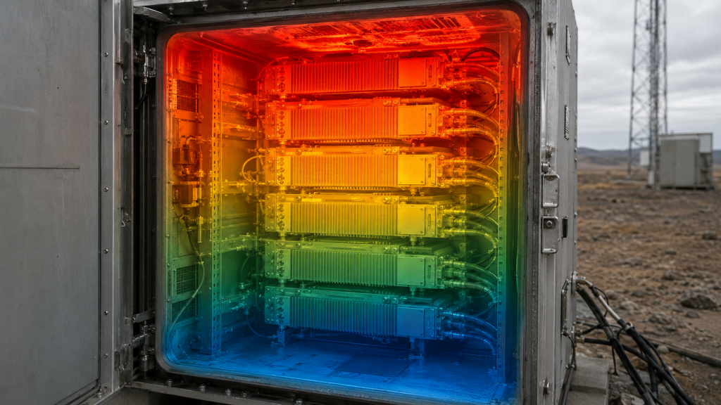
This is where it gets interesting. Multiple heat-generating modules share identical mounting rails. Power supplies sit directly below sensitive RF frontend blocks. Heat rises naturally through convection currents. Lower units bake whatever sits above them mercilessly. We call this phenomenon thermal stacking. Every watt dissipated below raises intake air temperatures for overhead equipment. An amplifier rated for fifty degrees Celsius ambient suddenly ingests sixty-degree exhaust air.
● Intake temperatures rise
● Linear regions shrink
● Harmonics worsen
Gain compression thresholds drop rapidly under elevated thermal stress. Your linear operating region shrinks considerably. Saturation occurs at much lower input drive levels. Harmonics worsen significantly because active devices operate closer toward non-linear extremes. We see third-order intermodulation products spike uncontrollably during these events. System linearity collapses entirely across broadband spectrums. Engineers must calculate total dissipated wattage per rack accurately. You must physically space high-power components apart deliberately. Thermal stacking ruins cascade link budgets if left unmanaged during initial mechanical layout phases. We measure ambient temperatures reaching seventy degrees near top racks routinely. Equipment installed highest suffers most from cumulative thermodynamic negligence.
Thermal Stacking Effects
| Rack Position | Inlet Temperature | Gain Compression Shift |
| Bottom Rack Unit | 30 degrees Celsius | Nominal |
| Middle Rack Unit | 45 degrees Celsius | 1 dB reduction |
| Top Rack Unit | 65 degrees Celsius | 3 dB reduction |
4. How Do We Use Spectrum Analyzers to Diagnose Gain Drift?
Live Diagnostic Techniques
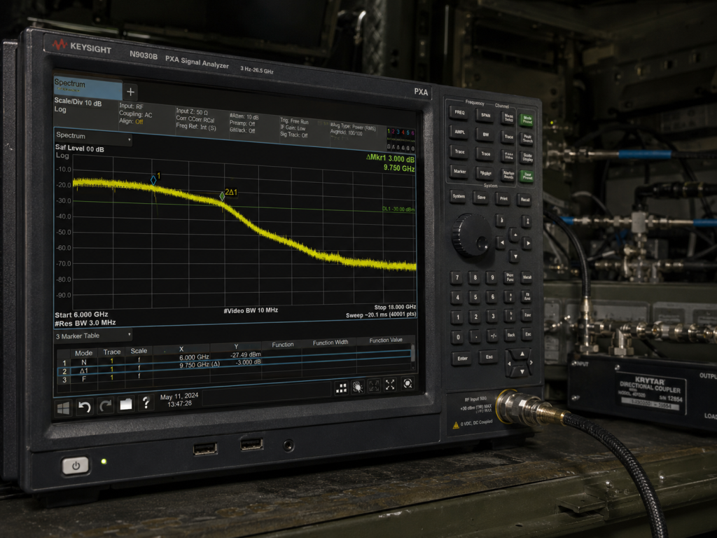
You might be wondering. How do technicians identify these exact failures onsite? We rely heavily upon spectrum analyzers configured for continuous max-hold sweeps. First connect directional couplers inline right before transmitting antennas. Monitor forward coupled ports continuously while running typical modulation schemes. Observe peak amplitude markers drifting downward slowly over thirty minutes. A cold start usually looks completely normal. As cabinet internals heat up you will witness noticeable trace sinking.
● Monitor forward power
● Track reverse power
● Set marker deltas
Set marker delta functions measuring initial versus hot state amplitudes. You often see three decibel differences confirming severe thermal degradation. Technicians should also monitor reverse coupled ports simultaneously. High VSWR readings might indicate heated antenna match shifting rather than amplifier issues. However if return loss remains stable while forward power drops we isolate our fault directly toward active amplification stages. Tracking generator sweeps overlaying live traces confirm wideband flatness degradation over time. These instrument techniques separate environmental faults from hard component failures definitively. Always calibrate test cables mitigating inherent coaxial loss variations first. Accurate baseline measurements empower technicians finding subtle performance drops quickly.
5. What Are the Cascading Effects on System Noise Figure?
Chain Reaction Failures
Ready for the good part? Decreasing gain at power amplifier stages impacts entire transmit-receive chains. Radar systems depend upon strict amplitude stability maintaining target cross-section accuracy. Thermal drift changes output phase relationships slightly alongside amplitude drops. Phased array antenna beamforming degrades when individual cabinet amplifiers drift at different rates. Furthermore electronic warfare systems lose jamming effectiveness if transmit power sags mid-mission. Every decibel lost means exponentially less power reaching distant adversaries.
● Target accuracy degrades
● Jamming power drops
● Noise figure rises
High temperatures also increase thermal noise floors inherently per basic physics equations. Higher internal device temperatures raise kTBF noise contributions measurably. You lose dynamic range from both ends simultaneously. Peak power drops while noise floors rise slightly. This dual penalty squeezes available signal noise ratios severely. System architects rarely account for hot-state dynamic range compression adequately. They rely too heavily upon cold-plate specifications printed on pristine factory datasheets. Real-world engineering requires calculating worst-case thermal cascade parameters rigorously. Receiver sensitivity drops drastically alongside transmitter power reduction simultaneously. Entire mission profiles collapse whenever thermal budgets fail.
RF Performance Parameter Shifts
| Electrical Parameter | Cold State | Hot State |
| Output Power | 500 Watts | 250 Watts |
| VSWR Tolerance | 1.5:1 | Triggers alarm |
| Harmonics | -15 dBc | -8 dBc |
6. How Does GaN Technology Mitigate Thermal Runaway?
Semiconductor Physics
Listen to this. Older LDMOS devices suffer greatly under extreme heat stress. They exhibit severe current droop phenomena inside sealed racks. Modern designs utilize Gallium Nitride technology explicitly fighting these environmental constraints. The CRF-PA-6000M18000M-500W relies completely upon advanced GaN architecture. Gallium Nitride offers superior thermal conductivity compared against traditional silicon counterparts. These semiconductor junctions withstand much higher absolute operating temperatures safely. Higher bandgap voltages allow engineers driving devices harder without triggering catastrophic breakdown mechanisms.
● High thermal conductivity
● Wide bandgap physics
● Superior transconductance
GaN transistors maintain transconductance better across wide temperature gradients. You experience far less parameter shift when internal cabinet air reaches fifty degrees Celsius. This material science advantage translates directly into stable RF performance. System integrators notice fewer calibration alarms triggering during extended field tests. Utilizing wide-bandgap materials represents our strongest defense against harsh thermal realities. Choosing inferior substrates guarantees premature field failures within confined spaces. Silicon fails rapidly trying passing identical RF currents. Investing heavily in wideband gap materials saves massive field replacement costs.
7. What Are the Mechanical Constraints of Air Cooling in RF Amplifiers?
Airflow Impedance Dynamics
Let me explain. The model CRF-PA-6000M18000M-500W uses active air cooling mechanisms. We package this beast inside a substantial chassis measuring roughly 800mm deep. High-power fans push massive CFM volumes across internal finned heatsinks. However these fans require unrestricted intake paths functioning correctly. Cramming this unit flush against cabinet doors chokes airflow instantly. Airflow impedance increases dramatically when exhaust ports face solid metal walls. Back-pressure forces hot air recirculating inside amplifier chassis.
● Fan stall events
● Back-pressure buildup
● Recirculation loops
Internal thermistors will trigger over-temperature protection circuits rapidly. Engineers must leave adequate clearance around equipment utilizing forced air dissipation. We recommend calculating cabinet total airflow exchanging rates mathematically. If internal rack fans move less air than installed equipment requires failure becomes imminent. Mechanical layout dictates electrical survival rates directly. We cannot cheat basic thermodynamic principles substituting wishful thinking instead. Static pressure builds quickly inside unvented metal enclosures. Fans stall out pushing air against solid physical boundaries.
CRF-PA-6000M18000M-500W Specifications
| Specification | Value | Data Source |
| Frequency Range | 6,000 – 18,000 MHz | |
| Rated Output | 500 W | |
| Dimension | 800mm deep | |
| Connector | WRD650 Output |
8. Why Does the CRF-PA-6000M18000M-500W Excel in High-Temperature Racks?
Purpose-Built Resilience
Now consider this. CorelixRF engineered this specific unit handling harsh realities head-on. It delivers five hundred watts rated output power reliably. Frequency coverage spans 6,000 reaching 18,000 MHz hitting critical X and Ku bands. We achieved 57 dB typical gain alongside twenty decibels adjustable range. This adjustability lets technicians compensate manually if external system losses change. Built-in protection circuits monitor over-voltage over-temperature and over-drive conditions constantly.
● High power output
● Broad frequency range
● Comprehensive protection loops
If cabinet heat becomes truly unsurvivable internal logic shuts down bias voltages protecting expensive GaN dies. It also monitors VSWR continuously preventing reflected energy damage. Operators interface via RS485 or LAN connections monitoring health status remotely. You never need opening sealed racks physically checking fault LEDs. This model thrives specifically because we designed every protection loop anticipating closed-box deployments. It expects terrible thermal management externally surviving despite severe conditions. Standard silicon models melt attempting similar feats. We prioritize physical survival above theoretical laboratory benchmarks.
9. How to Implement Effective Heat Dissipation for 500W Output?
Advanced Cooling Strategies
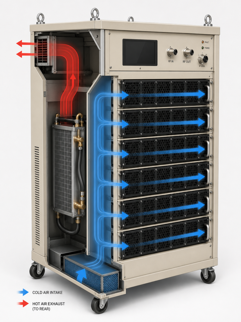
Here is a pro tip. Generating five hundred watts RF energy creates substantial waste heat. Assuming typical GaN efficiency you must dissipate roughly another five hundred watts thermally. Closed cabinets require specialized cooling strategies handling this load. Liquid-to-air heat exchangers mounted on rack doors offer excellent mitigation. They cool internal air before passing intakes. Alternatively ducted exhaust configurations push hot air completely outside equipment shelters. You must isolate intake streams from exhaust streams physically.
● Isolate intake streams
● Install blanking panels
● Deploy heat exchangers
Using blanking panels prevents hot exhaust recirculating back toward front intake vents. We mandate installing temperature sensors near amplifier air inlets verifying actual operating conditions. Never rely upon ambient room thermostats mounted miles away. If inlet air exceeds fifty degrees Celsius you must upgrade cabinet HVAC systems immediately. Proper thermal management requires treating air pathways identically like high-frequency transmission lines. Any mismatch causes disastrous reflections hindering performance. Treating heat dissipation carelessly destroys expensive RF assets rapidly. Solid thermodynamic engineering prevents catastrophic electrical failures entirely.
Integration Checklist
| Check Item | Pass Criteria | Failure Indicator |
| Power Supply | AC 380V±10% | Voltage droop |
| Control Link | RS485 / LAN | Timeout errors |
| Spurious Emission | Below -60 dBc | High noise floor |
10. What Are the Final System Integration Checks for Radar & EW?
Rigorous Field Verification
Let’s wrap this up. Final integration demands rigorous stress testing before field sign-off. Do not just test S-parameters briefly turning units off again. Run full CW power continuously across worst-case frequencies for several hours. Seal rack doors shut exactly mimicking operational field states. Monitor RS485 telemetry closely watching internal temperatures plateau. Verify output power remains within specified minus six decibels up toward plus six decibels flatness tolerances.
● Run CW power
● Seal rack doors
● Verify flatness tolerances
Check harmonic levels staying below minus eight dBc. Spurious emissions must never exceed minus sixty dBc even when running hot. Any degradation beyond these datasheet limits indicates inadequate rack-level thermal design. Engineers must log these parameters meticulously establishing healthy baseline signatures. We use these baselines later diagnosing future field degradation confidently. Systematic verification prevents embarrassing failures happening during critical mission operations. Engineering truth reveals itself only after extended thermal soaking exposes weak links. Never trust short lab tests predicting long term field reliability. Hard engineering data beats theoretical assumptions every single time.
Conclusion
Troubleshooting signal anomalies requires understanding thermal dynamics thoroughly. Sealed metal cabinets introduce severe heat constraints impacting component linearity. The CorelixRF CRF-PA-6000M18000M-500W overcomes these challenges utilizing advanced GaN architecture alongside robust protection loops. Systems engineers must prioritize rigorous mechanical layout preventing catastrophic field degradation effectively. Contact our team acquiring further implementation data.
FAQ
Q1: What is gain drift in sealed metal cabinets?
Gain drift represents RF power reduction caused by extreme internal heat buildup restricting semiconductor transconductance.
Q2: How does thermal stacking work?
Lower rack units dissipate waste heat rising upwards heating overhead components causing severe cascading thermal failures.
Q3: Why does GaN technology perform better in high temperatures?
Gallium Nitride utilizes wide bandgap architectures offering superior thermal conductivity withstanding higher junction temperatures safely.
Q4: How can engineers measure RF anomalies onsite?
Technicians utilize spectrum analyzers running continuous max-hold sweeps tracking forward coupled amplitude drops over time.
Q5: What protection mechanisms does the CRF-PA-6000M18000M-500W include? This model integrates over-voltage over-temperature over-drive and VSWR monitoring circuits actively preventing hardware destruction.
Turn this RF requirement into a quotable specification
Use this article as a starting point for a buildable RF specification. Before quoting, CorelixRF normally checks frequency range, output power, gain flatness, duty cycle, load mismatch, thermal path, control interface, enclosure limits and acceptance data.
- thermal reliability articles – continue with related thermal drift, cooling and sealed-enclosure reliability notes
- RF power amplifier platforms – match the article topic to available RF power amplifier families
- solid state power amplifier page – review SSPA architecture when reliability and repeatable test data matter
- RFQ checklist – send the data buyers usually forget, including band, power, duty cycle, interface and test standard
- delivery documentation – check what documents can support incoming inspection, FAT review and long-term maintenance
- case studies – review similar engineering paths before sending an RFQ
- engineering contact – send the application notes, block diagram or target specification to engineering sales
For a faster review, send operating band, power target, modulation or waveform, antenna/load condition, cooling limit, mechanical envelope and target test standard through the RFQ or contact path.