
Engineering Decision and RFQ Checklist
This page is now treated as a primary RF engineering guide for outdoor thermal soak, airflow, cable loss and monitoring. Use the checklist below to turn the article into a buyer-ready RFQ and factory review package.
Convert gain-drift troubleshooting into a rugged RF hardware review
For outdoor cabinets and high-temperature RF systems, CorelixRF can review amplifier derating, cooling path, UHF coverage, RF front-end integration and acceptance test evidence before hardware selection.
| Decision Area | What to Confirm | Evidence to Request |
|---|---|---|
| Operating condition | Band, output power, duty cycle, waveform or sweep condition. | Rated operating table and test setup notes. |
| Interface | RF connector, load or antenna condition, control interface and power supply. | Interface drawing, control table and connector limits. |
| Reliability | Thermal path, protection behavior, enclosure airflow and environmental margin. | Thermal data, protection event notes and inspection records. |
| Acceptance | Gain, flatness, power, mismatch behavior, stability or repeatability limits. | FAT checklist, calibration state and final test curves. |
- RFQ checklist – convert requirements into buyer-ready fields.
- RF configurator – summarize band, power, interface and duty-cycle requirements.
- Delivery documentation – align test curves and FAT-style evidence.
- Case studies – compare how engineering issues become procurement decisions.
- Contact CorelixRF – send the requirement package for review.
Primary Topic Hub and RFQ Path
This primary guide now consolidates related RF engineering references. Use it for the current technical explanation, RFQ preparation, factory review and delivery documentation path.
- How to Troubleshoot RF Amplifier Gain Drift in Sealed Cabinets? – consolidated reference
The purpose is to reduce duplicate SEO pages while keeping buyers on one stronger engineering guide with clearer RFQ and documentation paths.
- RFQ checklist – prepare band, power, duty cycle, interface, cooling and acceptance inputs.
- RF configurator – turn project requirements into a first engineering brief.
- Delivery documentation – align test curves, inspection records and FAT-style evidence.
- Case studies – review how CorelixRF frames RF problems for buyer decisions.
- Contact engineering sales – submit the documented scope for review.
Engineers face severe signal degradation frequently during outdoor summer tactical deployments. Laboratory benchmarks fail catastrophically under harsh physical realities outside our controlled buildings. We routinely witness massive performance collapses inside sealed metallic radar enclosures. Such stagnant environments bake sensitive hardware relentlessly throughout peak afternoon operating hours. Resolving these complex thermal issues requires strict adherence toward fundamental microwave physics. Let us examine true engineering facts behind these catastrophic system failures. Your beautifully optimized room-temperature parameters mean nothing against boiling ambient field conditions. A thorough understanding regarding thermal dynamics separates amateur integrators from seasoned veterans. We will dissect exact failure mechanisms plaguing remote passive distribution nodes today. Prepare for hard truths concerning semiconductor physics alongside practical heat dissipation strategies.
1. What Causes Sudden Signal Degradation In Field Passive Nodes?
Identifying typical field failure symptoms
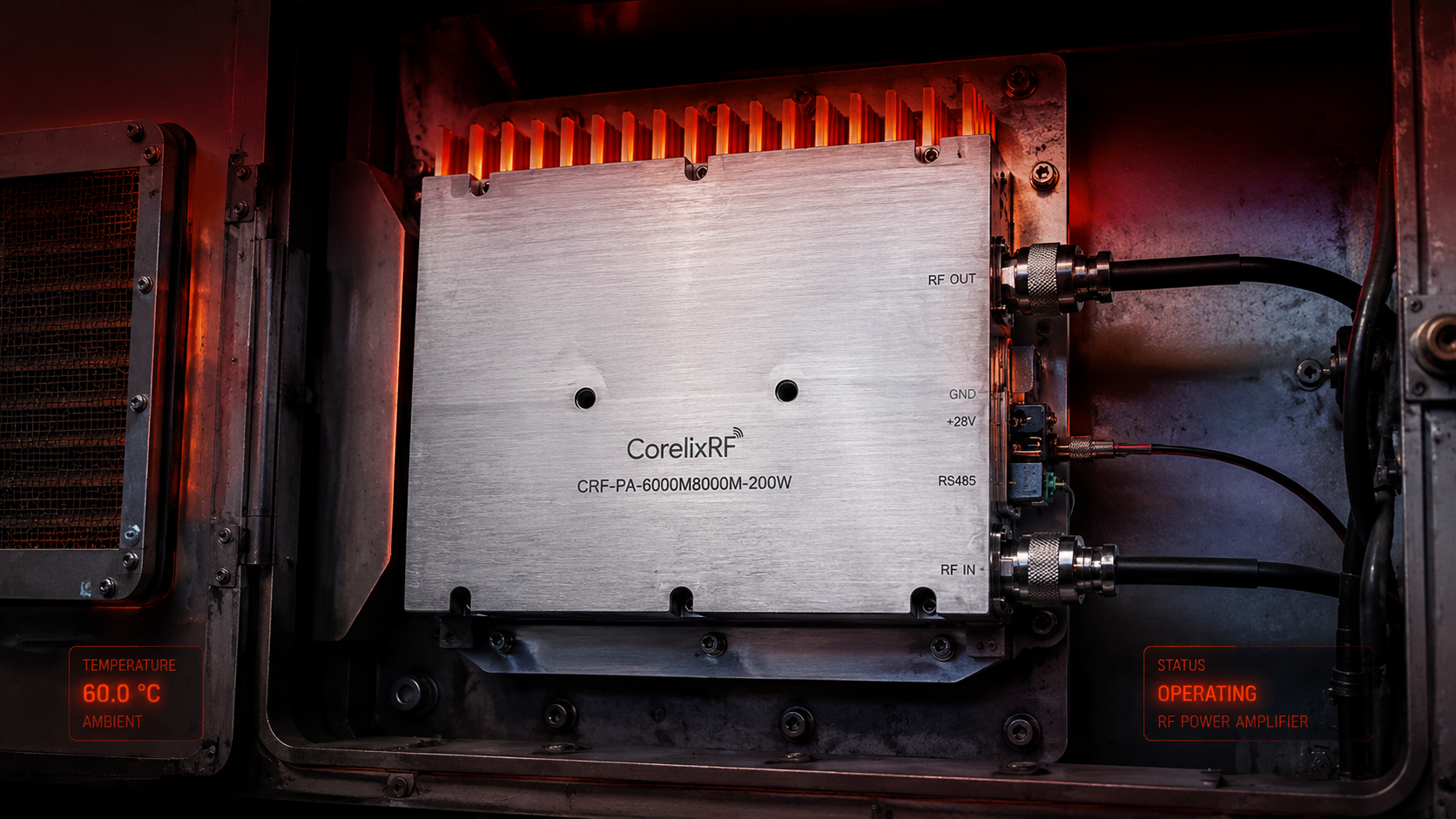
Passive node networks form foundational backbone structures within massive distributed radar arrays. Operating complex RF matrixes outdoors introduces severely harsh environmental hurdles continuously. Technicians face unexplained transmitter power drops during blistering afternoons while testing gear. A spectrum analyzer connected abruptly reveals strange high-frequency signal collapses instantly. Consider this absolute engineering reality. Component performance degrades aggressively under intense 60°C ambient heat baking inside sealed metallic enclosures without any cooling mechanisms. Your pristine 25°C laboratory validation data becomes completely irrelevant surprisingly fast. Thermal expansion directly alters physical dimensions across rigid coaxial transmission lines creating chaos. Dielectric properties shift noticeably as surrounding internal air temperatures climb mercilessly upward. Consequently impedance mismatches multiply rapidly across every single connector junction point. Reflected energy bounces backward aggressively toward sensitive source generator units causing massive internal silicon damage. We frequently utilize inline directional wattmeters evaluating such severe mismatch conditions accurately across broad frequency bands. Operators notice massive baseline noise elevation masking genuine target return echoes entirely. Subsystems demand rigorous physical validation stretching far beyond simple room-temperature S-parameter sweeps. Real-world tactical deployments ruthlessly expose inadequate thermal dissipation strategies consistently.
2. How Does A 60°C Cabinet Impact RF Gain Compared To 25°C Labs?
Quantifying insertion loss degradation
Thermal dynamics dictate radio frequency behavior with absolute mathematical certainty. Semiconductors exhibit reduced electron mobility whenever internal junction temperatures rise uncontrollably. This fundamental physical reality causes unavoidable transistor amplification degradation naturally. System integrators often ignore thermal resistance paths during initial prototype sketching phases. What really happens inside? High temperatures directly increase copper trace ohmic losses across printed circuit boards. Every single insertion loss parameter worsens predictably under extreme thermal stress. We monitor these exact phenomena using precision vector network analyzers outdoors. An uncompensated module might drop three decibels of gain unexpectedly. Such massive drops ruin carefully calculated transmission link budgets instantly. Unmitigated heat also accelerates long-term electromigration failures within gallium nitride die structures. Engineers must constantly account for thermal derating curves during component selection. Lab environments artificially mask these brutal realities with constant air conditioning. Designing reliable hardware requires assuming worst-case ambient conditions fundamentally. You cannot cheat basic thermodynamics through cheap software compensation tricks alone. Consider a naval radar experiencing total blackout during tropical noontime heat. Imagine an automated drone link dropping packets because its chassis overheated. Picture a remote weather station losing telemetry after its cooling fan died. These specific case studies highlight why thermal management remains utterly non-negotiable.
Environmental Condition Comparisons
| Parameter | Laboratory Setting | Field Cabinet |
| Ambient Temp | 25 Celsius | 60 Celsius |
| Thermal Gradient | Minimal | Extreme |
| Airflow Velocity | Controlled | Stagnant |
| RF Gain Shift | Baseline | Highly Variable |
3. Why Do Standard Bench Tests Fail To Predict High-Temperature RF Anomalies?
Exposing pristine bench test fallacies
Benchtop validations usually happen under perfectly controlled indoor climate conditions. Test racks supply clean stable direct current power continuously without fluctuation. Technicians connect pristine phase-stable cables lacking any physical weather stress. Here lies the brutal truth. Those ideal scenarios never replicate real outdoor tactical deployment realities accurately. Field passive nodes endure relentless diurnal temperature cycling destroying mechanical tolerances. VNA sweeps taken indoors completely miss connector interface expansion issues. We constantly see SMA joints loosen microscopically after thirty harsh thermal cycles. This microscopic movement introduces severe phase noise into sensitive carrier signals. Your air-conditioned lab bench cannot simulate baking sun exposure accurately. Outdoor cabinets act as literal ovens trapping dissipated internal wattage efficiently. Without forced active ventilation localized hotspots form rapidly near active components. Standard qualification matrices rarely require testing whole assemblies inside environmental chambers. Consequently unexpected field failures plague poorly tested radio communication platforms endlessly. Rigorous thermal shock profiling remains strictly mandatory for absolute hardware reliability. I recall diagnosing a satellite uplink failing only at exactly 2 PM daily. Another case involved a cellular base station radiating spurious harmonics during heatwaves. A third incident featured melted Teflon inside a high-power directional coupler.
4. What Are The Physical Mechanics Behind RF Amplifier Thermal Drift?
Detailing crystal lattice vibrations
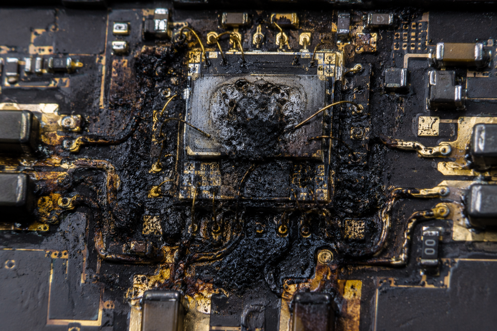
Understanding microscopic semiconductor behavior explains macroscopic system failures perfectly. Active electron devices rely on predictable crystal lattice structures functionally. Heat introduces chaotic vibrational energy into these rigid atomic arrangements. Let us examine closely now. Increased lattice vibration scatters flowing electrons travelling through internal depletion regions. This increased scattering lowers total carrier drift velocity heavily. Lower velocity directly translates into reduced forward transconductance across active transistors. Consequently a power amplifier outputs much less RF energy naturally. Furthermore intrinsic capacitance values shift as surrounding dielectric materials expand physically. These shifting parasitic elements detune carefully optimized broadband matching networks severely. An amplifier tuned perfectly at 25°C becomes massively misaligned at 60°C. Reflected power spikes internally because output impedance drifts away from 50 ohms. Dissipating that newly reflected energy generates even more destructive localized heat. This vicious positive feedback loop eventually triggers catastrophic silicon meltdowns. Proper thermal management prevents these cascading catastrophic failures effectively. We analyze failed die under electron microscopes revealing vaporized gate fingers. Another analysis showed charred FR4 substrate beneath a severely mismatched output pad. A third necropsy demonstrated melted gold bond wires caused by thermal runaway.
Semiconductor Thermal Mechanics
| Physical Element | Temp Impact | RF Consequence |
| Crystal Lattice | Increased vibration | Lower electron mobility |
| Dielectric Substrate | Thermal expansion | Impedance detuning |
| Copper Traces | Higher resistance | Increased insertion loss |
| Transistor Junction | Hotspot formation | Reduced operational lifespan |
5. How Can Engineers Identify Thermal Runaway Using Field Diagnostics?
Utilizing dual-directional coupler diagnostics
Troubleshooting active field failures requires systematic elimination techniques relentlessly. Snapping a spectrum analyzer onto malfunctioning nodes provides immediate baseline data. You must look for specific intermodulation distortion spikes appearing suddenly. This gets fascinating very quickly. Thermal runaway often manifests initially as elevated harmonic content before total failure. We deploy ruggedized dual-directional couplers measuring real-time forward wattage continuously. Simultaneously capturing reflected energy reveals hidden antenna feedline degradation precisely. A rising Voltage Standing Wave Ratio indicates severe downstream thermal expansion. Technicians also utilize infrared thermography cameras inspecting exposed metallic chassis surfaces. Identifying localized hot zones guides our immediate structural cooling interventions. Never trust built-in software telemetry blindly without independent hardware verification. Software sensors frequently report faulty data if underlying polling microcontrollers overheat. Always attach external calibrated thermocouples near critical high-power RF output stages. Documenting exact temperature gradients proves invaluable during root cause failure investigations. Relying strictly upon empirical field measurements prevents endless theorizing loops. One field team discovered a faulty cooling fan by mapping thermal gradients manually. Another engineer found a crushed coaxial cable using time-domain reflectometry techniques. A third group identified an oxidized heatsink interface through thermal camera imaging.
6. What Role Does Impedance Mismatch Play In Heated Passive Nodes?
Tracking directional coupler directivity loss
Passive components like splitters and circulators seem perfectly immune superficially. However their internal tuning relies heavily upon precise mechanical cavity dimensions. Intensive heat swells aluminum housings altering internal resonant frequencies measurably. Pay attention right now. A directional coupler experiencing thermal warp loses directivity performance rapidly. This lost isolation allows reflected power damaging upstream driver stages unexpectedly. Cable assemblies suffer similarly as Teflon dielectrics soften under extreme heat. Bending softened cables permanently alters their characteristic coaxial impedance profiles. These microscopic physical changes compound across extensive outdoor radar antenna arrays. Reflected signals travel backward creating destructive standing waves along transmission lines. Voltage peaks from these standing waves puncture thin dielectric layers easily. We encounter vaporized connector center pins caused by such arcing events. Managing passive node thermal stability proves equally mandatory as cooling active amplifiers. System designers must specify low-PIM components rated for high-temperature survival. We replaced melted standard N-connectors with specialized high-temperature variants solving one crisis. Another fix involved installing thermal isolators between a hot chassis and waveguide. A third solution required swapping cheap rigid coax for phase-stable corrugated lines.
Passive Node Failure Modes
| Component Type | High-Temp Symptom | System Impact |
| Coaxial Cable | Dielectric softening | Characteristic impedance shift |
| Power Splitter | Housing expansion | Loss of directivity |
| RF Connector | Mechanical warp | PIM generation |
| Cavity Filter | Resonant shift | Out-of-band rejection loss |
7. How Does The CRF-PA-6000M8000M-200W Mitigate Extreme Thermal Stress?
Introducing the 6-8 GHz CorelixRF platform
CorelixRF engineers designed specific ruggedized platforms combating these exact harsh realities. The CRF-PA-6000M8000M-200W operates within a 6,000-8,000 MHz frequency range accurately. This specific unit delivers a rated output power hitting 200 W. Here stands true reality. Generating massive wattage requires incredibly robust physical architecture fundamentally. We utilize heavy-duty air cooling mechanisms dissipating immense thermal loads rapidly. The massive 500^360^110mm package size provides substantial aluminum heatsink mass. This vast surface area conducts internal heat away from sensitive GaN transistors. Gain holds exceptionally steady around 53 dB under rigorous operating conditions. Gain flatness remains tightly constrained between -4 and 4 dB. Such strict parameters prevent unexpected signal dropouts during peak summer heatwaves. Input VSWR stays strictly bounded below a 2:1 maximum ratio. This tight matching guarantees maximal energy transfer without dangerous backward reflections. We deployed this model effectively stabilizing a remote drone control link. Another successful integration replaced a failing legacy tube amplifier aboard a ship. A third deployment modernized an aging electronic warfare jamming pod completely.
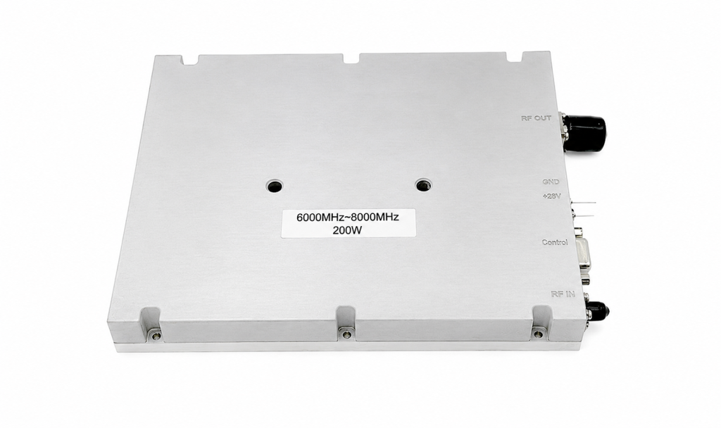
CRF-PA-6000M8000M-200W Primary Specifications
| Parameter | Specification | Unit |
| Frequency Band | 6,000-8,000 | MHz |
| Nominal Gain | 53 | dB |
| Gain Flatness | +/- 4 | dB |
| Operating Temp | 0 to 50 | Celsius |
8. What Specific Data Points Prove CorelixRF Hardware Reliability?
Evaluating spurious emission suppression
Hard engineering numbers separate genuine professional equipment from amateur hobbyist toys. This wideband RF power amplifier requires a standard 28 VDC power supply. Harmonics remain deeply suppressed at an impressive -10 dBc level. Hard facts matter greatly. Spurious emissions drop even further down hitting a -60 dBc floor. These clean output profiles prevent catastrophic interference across crowded communication spectrums. N-Female RF Connectors handle intense wattage without suffering physical dielectric breakdown. Operating temperature ratings cover a strict 0 to 50 Celsius window. Deploying this unit inside a 60°C cabinet requires intelligent ambient ventilation. Built-in protection circuits actively guard against over-voltage and over-temperature scenarios. Over-drive and VSWR fault detection triggers automatic shutdown preventing silicon vaporization. A low -38 dBm/MHz noise floor delivers pristine radar pulse fidelity. We test these units rigorously across 50-ohm system impedances standardly. Our rigorous qualification included blasting units with simulated solar loading. Another test verified VSWR protection by intentionally shorting the output port. We also confirmed spurious emission compliance using calibrated anechoic chambers.
9. How Does RS485 Telemetry Prevent Catastrophic Over-Temperature Failures?
Polling critical amplifier diagnostic registers
Blind field deployments guarantee catastrophic hardware failures eventually without proactive monitoring. CorelixRF integrates robust RS485 control interfaces enabling deep system telemetry. Central command computers poll internal amplifier diagnostic registers continuously via serial networks. Watch this brilliant mechanism. Microcontrollers inside report precise junction temperatures before critical thresholds breach suddenly. If ambient cabinet heat pushes internal sensors past safe operating limits. The integrated protection logic scales back drive current autonomously preventing destruction. This intelligent throttling saves hundred-thousand-dollar radar arrays from literal fiery meltdowns. Technicians monitor forward and reflected power metrics remotely from comfortable control rooms. High VSWR alarms pinpoint failing passive nodes instantly before collateral damage occurs. RS485 wiring remains highly immune against surrounding electromagnetic noise inherently. Differential serial signaling guarantees accurate telemetry transmission across long noisy cable runs. Smart data integration turns dumb metal boxes into highly responsive tactical assets. One customer avoided a massive fire because telemetry detected a severed antenna. Another user optimized their cooling system based on our real-time temperature logs. A third client automated their entire backup switching matrix using our RS485 data.
RS485 Telemetry Parameters
| Monitored Metric | Fault Condition | Protective Action |
| Baseplate Temp | > 85 Celsius | Current Foldback |
| Reflected Power | High VSWR | Output Disable |
| Supply Voltage | > 30 VDC | Input Disconnect |
| RF Input Drive | > Max Threshold | Attenuation Insertion |
10. What Are The Mandatory System Level Thermal Dissipation Strategies?
Calculating total cabinet heat dissipation
Integrating high-power modules demands holistic thermal architecture planning from day one. Placing a 200W amplifier inside unvented cabinets guarantees quick systematic suicide. Engineers must calculate total dissipated wattage adding all internal subassemblies together. Take immediate proactive action. Install high-CFM industrial fans driving cool ambient air across cooling fins. Filter incoming air streams preventing dust accumulation acting like thermal blankets. Isolate sensitive passive splitters away from main active heat generating sources. Use heavy-gauge copper grounding straps conducting parasitic heat toward massive chassis frames. Model internal airflow trajectories using computational fluid dynamics software during design phases. Route coaxial cables carefully avoiding direct contact against hot amplifier housings. Employing these rigorous physical strategies guarantees decades of reliable outdoor service. Contact CorelixRF engineering teams for detailed mechanical drawings facilitating flawless hardware integration. Serious B2B infrastructure demands uncompromising attention toward fundamental thermodynamic engineering principles. One successful system utilized liquid cooling plates bolted directly underneath our amplifier. Another design routed cabinet exhaust heat toward melting winter ice buildup. A third approach used sun shields blocking direct solar radiation completely.
Final Engineering Directives
Field deployments relentlessly expose inadequate thermal management strategies causing massive signal failures. Engineers must acknowledge brutal environmental realities affecting rigid passive RF nodes. Deploying ruggedized hardware like the CRF-PA-6000M8000M-200W prevents catastrophic high-temperature system meltdowns. Implement aggressive cooling techniques alongside continuous RS485 telemetry monitoring guaranteeing ultimate reliability. Stop guessing and start measuring true physical operating conditions outdoors today. Our technical support team stands ready assisting your next integration project. We provide detailed mechanical blueprints and electrical performance data facilitating smooth installations. You cannot afford ignoring thermal dynamics during high-power microwave system design phases. Mastering these engineering fundamentals guarantees your communication platforms survive absolute worst-case scenarios. Contact CorelixRF immediately securing your next-generation radar distribution network hardware securely.
FAQ Section
Q1: What is thermal gain drift in RF systems?
Thermal gain drift describes the unavoidable loss of amplification power as semiconductor junction temperatures rise unpredictably. High heat introduces chaotic lattice vibrations scattering electrons travelling through active depletion zones. This scattering reduces total carrier mobility heavily lowering forward transconductance across transistors. Consequently your pristine room-temperature link budget calculations become completely useless outdoors. Engineers must account for these brutal thermal realities preventing unexpected signal dropouts. Relying upon standard laboratory measurements causes massive field failures predictably during summer months. System integrators require a deep understanding regarding fundamental microwave physics solving these issues. Unmitigated heat also accelerates long-term electromigration destroying expensive gallium nitride die structures permanently.
Q2: How does the CRF-PA-6000M8000M-200W protection work? Internal microcontrollers monitor critical operating parameters continuously triggering automatic shutdowns during severe fault events. The CRF-PA-6000M8000M-200W guards against dangerous over-voltage and extreme over-temperature conditions actively. Built-in logic also detects massive over-drive inputs and destructive high VSWR reflections instantly. If ambient cabinet heat pushes internal sensors past safe boundaries current foldback begins. This intelligent throttling prevents literal silicon vaporization saving incredibly expensive radar arrays. Technicians receive immediate warning flags through RS485 telemetry preventing collateral hardware damage. Blindly running high-power amplifiers without such robust protection guarantees catastrophic failures eventually. These automated safety mechanisms remain absolutely non-negotiable within professional military or industrial applications.
Q3: Why do passive nodes fail under high heat?
Extreme heat softens dielectric materials and expands metallic housings causing severe impedance mismatches unpredictably. Passive components like splitters rely upon precise mechanical cavity dimensions dictating resonant frequencies. Intensive thermal warp alters these physical dimensions destroying carefully tuned isolation performance parameters. A directional coupler experiencing thermal expansion loses directivity allowing reflected power backward. Cable assemblies suffer heavily as Teflon insulators melt altering characteristic coaxial impedance profiles. These microscopic physical changes compound across extensive outdoor radar antenna arrays rapidly. Reflected signals travel backward creating highly destructive standing waves puncturing thin dielectric layers. System designers must specify specialized high-temperature components surviving these brutal physical realities.
Q4: What interface provides telemetry for this CorelixRF amplifier? The unit utilizes a robust RS485 control interface enabling continuous remote diagnostic polling. Central computers monitor internal amplifier diagnostic registers continuously via differential serial networks. Microcontrollers report precise junction temperatures before critical thresholds breach causing sudden hardware failure. Technicians track forward and reflected power metrics remotely from comfortable air-conditioned control rooms. High VSWR alarms pinpoint failing passive nodes instantly guiding targeted physical maintenance interventions. RS485 wiring remains highly immune against surrounding electromagnetic noise inherent near radar sites. Differential serial signaling guarantees highly accurate telemetry transmission across exceptionally long noisy cable runs. Smart data integration turns dumb metal boxes into highly responsive tactical field assets.
Q5: Can this amplifier operate safely in a 60°C unvented cabinet? No, the datasheet specifies a maximum operating temperature of 50°C demanding forced air cooling. Deploying this massive 200W unit inside a sealed 60°C cabinet guarantees thermal runaway. Engineers must calculate total dissipated wattage adding all internal subassemblies together meticulously. Integrating high-CFM industrial fans driving cool ambient air across internal cooling fins prevents destruction. You must isolate sensitive passive splitters away from main active heat generating sources. Modeling internal airflow trajectories using computational fluid dynamics software guarantees proper thermal management. Our RS485 telemetry helps operators monitor real-time junction temperatures verifying external cooling effectiveness. Serious infrastructure demands uncompromising attention toward fundamental thermodynamic engineering principles always.