

Key Design Points for High-Power Passive Nodes: Engineering Practice in Combating Gain Drift Caused by 25°C Lab vs. 60°C Field Chassis High Temperatures. System integrators face severe gain drift when moving passive nodes from laboratories into field chassis enclosures. We evaluate specific physical mechanisms driving these failures while introducing robust thermal architecture. My decades evaluating RF hardware failures provides an objective framework outlining exact component behaviors under severe thermal stress.
1. Why Do Passive Nodes Suffer Catastrophic Failures at 60°C System Environments?
● Thermal accumulation physics in restricted chassis
● Discrepancy between VNA calibration and field reality
● Link budget collapse mechanisms
Environmental Discrepancies in Field Testing
Here is the deal, laboratory conditions mask actual physical stress placed on high-frequency components. Engineers routinely characterize networks using vector network analyzers operating under controlled ambient conditions. Moving those same assemblies into restricted field enclosures fundamentally alters thermal dissipation pathways. Semiconductor junction temperatures rise uncontrollably without proper ventilation channels. Carrier mobility within active devices decreases exponentially as internal heat accumulates past specification limits. Passive nodes depend upon stable signal pass-through characteristics without active feedback loops. Any insertion loss variation directly degrades system dynamic range. Reflected energy bounces between mismatched interfaces, further exacerbating localized heating. We see this manifested as abrupt output power drops on field spectrum analyzers. Link budgets calculated at room temperature become entirely invalid once rackmount ambient exceeds fifty degrees Celsius. System architects must account for raw physics rather than relying upon idealized simulation models. My decades diagnosing failing microwave chains reveal a consistent pattern involving neglected environmental variables. Heat acts like a slow poison destroying delicate RF matches over time. You cannot ignore ambient air gradients when deploying sensitive receiving arrays outdoors.
High-Frequency Parameter Shifts
| Parameter | Room Temperature (25°C) | High Temperature (60°C) | Impact |
| Gain | Stable 47 dB | Droops severely | Link budget deficit |
| VSWR | Nominal 1.2:1 | Approaches 2.0:1 | Protection triggering |
| Output Power | 50 W Continuous | Thermal fold-back | System degradation |
2. How Does Temperature Shift Alter RF Amplifier Gain Profiles?
● Semiconductor mobility degradation specifics
● Matching network impedance variations
● Continuous wave output saturation limits
Material Science Behind Gain Droop
You might be wondering, why precise matching networks suddenly behave erratically inside hot metal boxes. High-frequency transistor transconductance drops predictably when junction temperatures climb much above standard room levels. Dielectric materials used across printed circuit boards exhibit temperature-dependent permittivity shifts. This physical reality detunes carefully designed input networks operating near 9000 MHz frequencies. An amplifier delivering forty-seven decibels of gain at standard ambient conditions will inevitably exhibit severe droop during continuous wave operation outdoors. Reflected power spikes trigger internal standing wave ratio alarms, forcing protective circuitry activation. Field technicians often mistake these automated power reductions for catastrophic hardware failures. We constantly measure degraded S21 parameters using calibrated benchtop equipment immediately after removing suspect modules from heated environments. Component selection processes must prioritize substrates featuring ultra-low thermal coefficients. Ignoring fundamental material properties guarantees unacceptable variance across your entire operational bandwidth. Hardware degrades rapidly without adequate cooling airflow passing across hot surfaces.
3. What Are The Hidden BOM Traps in Amplification Stages?
● Substrate dielectric constant shifts
● Inadequate thermal via placements
● False promises of commercial grade components
Heat Traps in Printed Circuit Boards
What is the real story behind sudden field breakdowns involving seemingly high-quality bill of materials selections? Many procurement teams specify commercial-grade capacitors exhibiting massive capacitance variations once internal temperatures surpass forty degrees. RF traces routed over standard FR4 substrates suffer massive insertion loss penalties at high frequencies. Designers frequently neglect proper thermal via distribution beneath high-power active devices. This oversight traps dissipated heat directly under sensitive semiconductor junctions, creating localized destructive hotspots. Passive node architectures require completely uncompromised components capable of handling extreme continuous thermal stress. You cannot cheat basic thermodynamics by applying software corrections across degraded analog front ends. Replacing marginal parts with military-grade equivalents prevents sudden dielectric breakdowns during harsh summer deployments. My field experience analyzing burned amplifier stages always points backwards toward compromised thermal dissipation decisions made during initial schematic drafting. Engineers blindly trusting vendor datasheets often face brutal reality checks during outdoor summer trials.
CorelixRF Amplifier Specifications
| Specification | Value | Unit | Condition |
| Frequency Range | 7000 – 9000 | MHz | Continuous |
| Rated Output Power | 50 | W | 50 Ohm system |
| Gain Flatness | -4 to +4 | dB | Full band |
4. Why Is The CRF-PA-7000M9000M-50W Selected For This Thermal Challenge?
● Forced air cooling integration
● 47dB gain stability constraints
● 50W output power sustainability
Engineering Continuous Output Power
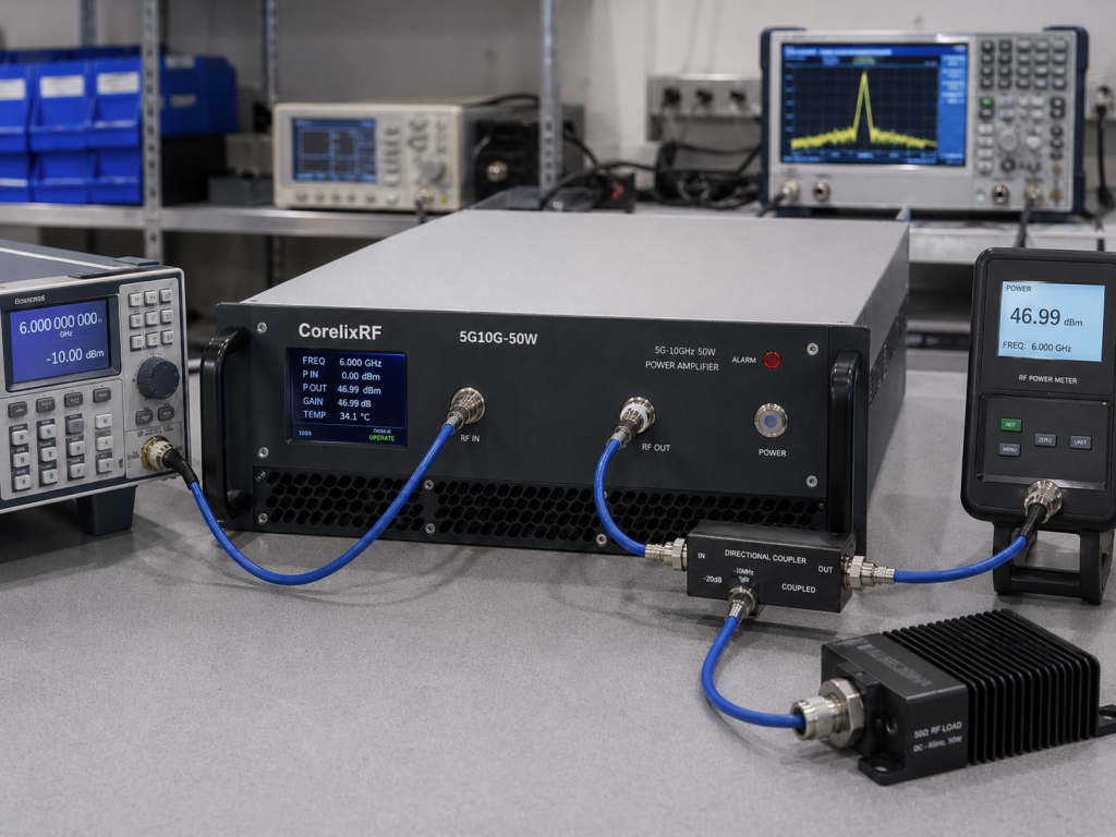
This is where it gets interesting, analyzing how specific hardware tackles aggressive heat accumulation head-on. Our engineering team designed this specific wideband unit primarily for testing and measurement within communication or aviation control sectors. Delivering fifty watts of continuous output power requires massive internal heatsink structures coupled with forced air cooling mechanisms. Standard modules fail under such extreme loads, but this design maintains a stable forty-seven decibel gain profile. Built-in protection systems immediately monitor over-voltage, over-temperature, and overdrive conditions automatically. A nineteen-inch 3U rackmount package provides adequate physical volume for separating sensitive control logic away from high-power RF transistors. System integrators require consistent performance across seven thousand through nine thousand megahertz without unexpected power drops. We verified operational limits repeatedly using rigorous automated test sequences prior toward release. Operating heavy machinery mandates strict adherence toward specified environmental operational boundaries.
5. How Does The 7000-9000 MHz Frequency Range Respond To Chassis Heat?
● Wavelength considerations inside metal enclosures
● Standing wave ratio (VSWR) protection activation
● Reflected power dissipation
Microwave Wavelength Sensitivities
Ready for the good part, investigating microwave behavior confined inside tightly packed metal enclosures. Short wavelengths corresponding with X-band frequencies become highly susceptible toward minor mechanical expansions caused by extreme heat. Connectors like N-Female interfaces experience slight physical deformations altering standard fifty-ohm impedance characteristics. These microscopic shifts generate massive reflected energy traveling backwards through your transmission lines. Specified input VSWR parameters representing a 2:1 ratio dictate hard physical limits before protective circuits engage. Excess reflected energy converts directly into additional waste heat, compounding an already dangerous thermal runaway scenario. Spurious emissions remain suppressed below minus sixty decibels relative only if baseplate temperatures stay stabilized. We consistently observe VNA curve collapses near upper band edges when internal cooling fans fail during field deployments. Harmonic containment requiring minus fifteen decibels demands linear operation devoid of saturation artifacts. Physical wavelength properties dictate severe penalties for mismatched loads. You cannot negotiate against fundamental electromagnetic wave propagation rules.
Protective Circuitry Mechanics
| Threat | Detection Method | System Response | Hardware Component |
| Over-voltage | Voltage comparator | Shuts down bias | DC control board |
| Over-temperature | Thermocouple | Engages alarms | Baseplate sensor |
| Over-drive | RF coupler | Limits input | Pre-amp stage |
6. What Architectural Changes Mitigate 60°C Induced Gain Drift?
● Adjustable gain implementation techniques
● Pre-distortion and compensation networks
● Baseplate temperature monitoring
Hardware Compensation Architecture
But here is the kicker, hardware architecture dictates ultimate survivability long before any software boots up. Engineers must implement closed-loop baseplate temperature monitoring feeding directly into variable attenuator control circuits. Providing twenty decibels of adjustable gain allows operators enough headroom for compensating predictable thermal droop. High-power stages utilize advanced bias networks tracking localized heat generation near active die areas. This physical compensation prevents device transconductance from dropping dramatically when ambient air reaches fifty degrees Celsius. RS485 and LAN interfaces enable remote polling of internal telemetry parameters during continuous outdoor operation. You cannot fix hardware failures using software alone once physical damage occurs at the semiconductor junction level. Designing heavy copper heat spreaders directly underneath power amplifiers eliminates concentrated thermal bottlenecks entirely. Robust design demands anticipating worst-case environmental extremes during initial prototyping phases. Heat destroys uncompensated microwave components without mercy.
7. How To Execute Proper Link Budgets For High-Temperature Deployments?
● Factoring -4 to +4 dB gain flatness into models
● Cascaded noise figure degradation
● Margin allocation strategies
Calculating Margin Degradation
Truth be told, spreadsheet calculations frequently fail because designers ignore maximum parameter deviations under severe physical stress. A stated gain flatness ranging from minus four through positive four decibels severely impacts cascaded dynamic range. Hot components generate much higher thermal noise floors, degrading receiver sensitivity profiles simultaneously. Engineers calculating nominal zero decibel-milliwatt input levels must assume worst-case scenarios regarding internal cable losses. We recommend allocating at least three extra decibels specifically addressing temperature-induced parameter shifts. Operating heavy hardware requires constant AC 220V power supplies delivering clean current without low-frequency ripple. Harmonic distortion remains restricted below minus fifteen decibels only when amplifier stages avoid deep saturation. Rigorous mathematical modeling prior toward hardware procurement saves countless hours troubleshooting random field anomalies later. Cascaded chain analysis mandates tracking absolute maximum operating limits across every single active component.
Mechanical Enclosure Data
| Physical Trait | Measurement | Unit | Application Purpose |
| Chassis Width | 483 | mm | Rack mount integration |
| Chassis Depth | 432 | mm | Heat sink volume |
| Chassis Height | 147 | mm | Airflow channeling |
8. What Role Does Thermal Dissipation Design Play In Stability?
● 19-inch 3U rackmount physics
● Airflow routing over hot components
● Heat sink fin geometry impacts
Fluid Dynamics in Rackmounts
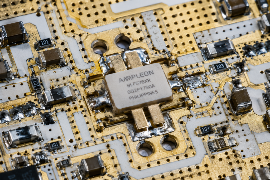
Look closely at the data, physical chassis dimensions directly dictate peak sustainable continuous wave operation capabilities. A package measuring 483 by 432 by 147 millimeters contains substantial aluminum mass designed specifically for absorbing transient thermal spikes. Forced air cooling dictates specific fin spacing formulated for peak turbulent airflow velocity across heated surfaces. If system integrators block intake vents inside crowded cabinets, internal temperatures will skyrocket past safe limits rapidly. Passive nodes positioned adjacent toward other heat-generating modules suffer from severely reduced convective cooling efficiency. We utilize computational fluid dynamics software analyzing exact temperature gradients across every internal circuit board surface. Mounting high-power components onto thick metal baseplates guarantees immediate heat transfer away from delicate active die structures. Mechanical engineering remains just as critical as electrical schematic drafting when developing high-power radio frequency amplifiers. Ignoring thermal dynamics guarantees premature hardware failure.
9. How Can Engineers Verify Drift Using Hardware Instruments?
● Setting up localized heat chambers
● Tracking S21 parameters via vector network analyzers
● Real-time power meter observations
Laboratory Validation Methodologies
Let us be clear, bench testing requires exact replication of expected environmental extremes using calibrated environmental chambers. Technicians inject continuous sweep signals using network analyzers while simultaneously monitoring baseplate temperatures via attached thermocouples. Real-time power meters connected across output ports reveal exactly when internal gain blocks begin experiencing thermal compression. You must record S-parameters continuously as chamber temperatures slowly ramp from twenty-five toward sixty degrees Celsius. This methodical approach highlights specific frequency sub-bands suffering maximum insertion loss degradation during thermal cycling. Relying solely upon factory calibration sheets without performing independent verification testing borders on professional negligence. We routinely discover hidden resonance modes triggering unexpected spurious outputs during high-temperature stress evaluations. Swept frequency measurements expose subtle matching network vulnerabilities invisible during single-tone continuous wave tests. Field reliability requires brutal laboratory validation destroying weak prototypes early.
Field Integration Checklist
| Requirement | Verification Phase | Instrument Needed | Goal |
| Thermal Mapping | Prototyping | Thermal Camera | Identify hotspots |
| S-Parameter Sweep | Lab Validation | VNA | Confirm matching |
| Power Stability | Field Trial | Power Meter | Verify CW output |
10. What Is The Final Verdict On Sustaining Reliability?
● Summarizing systematic compensation methods
● Long-term deployment strategies
● System integrator action paths
Executing Long-Term Stability
The bottom line stays simple, mitigating severe thermal drift requires uncompromising component selection combined with massive mechanical cooling architectures. High-power passive nodes simply cannot survive harsh field conditions utilizing cheap consumer-grade printed circuit boards. System integrators must prioritize equipment featuring robust internal protections against over-voltage, over-temperature, and extreme standing wave ratios. Incorporating remote telemetry via RS485 connections allows predictive maintenance before catastrophic hardware failures actually occur. We strongly suggest reviewing complete mechanical drawings alongside electrical datasheets prior toward finalizing any rackmount layout configurations. Understanding core thermodynamic principles separates successful continuous deployments from frustrating weekend troubleshooting sessions. Physical reality always wins against overly optimistic spreadsheet predictions involving high-frequency radio waves. Never underestimate the destructive potential of trapped heat inside sealed metal enclosures. Build your networks assuming components will operate continuously near maximum thermal limits.
[Architecture Analysis] Key Design Points for High-Power Passive Nodes: Engineering Practice in Combating Gain Drift Caused by 25°C Lab vs. 60°C Field Chassis High Temperatures. Harsh thermal environments systematically degrade high-frequency amplifier parameters unless engineers deploy heavy-duty mechanical cooling architectures. The documented fifty-watt unit mitigates severe drift utilizing forced air alongside rigorous protective circuitry. Evaluate physical integration constraints meticulously before finalizing your next passive node deployment. Contact our engineering team today for detailed system integration guidance.
FAQ Section
Q1: What is thermal gain drift?
Thermal gain drift occurs when semiconductor junction temperatures rise, causing internal transconductance to drop predictably. This physical phenomenon reduces overall signal amplification capabilities across wideband frequency ranges.
Q2: How does forced air cooling work inside 3U chassis?
High-velocity fans push ambient air directly across massive aluminum heat sink fins attached beneath active RF transistors. This continuous airflow prevents localized heat accumulation from destroying sensitive die structures.
Q3: Does VSWR protection activate during thermal events?
Yes, thermal expansion alters connector impedance characteristics, causing excessive reflected energy. Built-in protective circuits detect these standing wave ratio spikes and immediately reduce output power preventing catastrophic failure.
Q4: Where do engineers measure chassis baseplate temperatures?
Technicians attach calibrated thermocouples directly onto thick copper spreaders located immediately beneath high-power amplifier stages. This provides accurate real-time thermal telemetry during continuous swept frequency laboratory testing.
Q5: Can software compensate for severe hardware thermal degradation?
Software cannot fix physically damaged semiconductors or melted dielectric substrates. Closed-loop control systems can adjust variable attenuators temporarily, but robust mechanical cooling remains the only permanent solution.
Convert thermal risk into measurable RFQ requirements
Thermal reliability should be specified with output power, duty cycle, ambient range, airflow or baseplate path, soak time, allowed gain drift and alarm behavior. These details help CorelixRF match the request to a standard or modified amplifier platform.
Recommended next step: send the operating band, output power target, duty cycle, load condition, control interface, protection or thermal limits and required FAT documents. CorelixRF can review this How to Prevent Thermal Gain Drift in Field RF Passive Nodes? requirement against standard RF amplifier platforms, RF front-end options and controlled customization paths.