
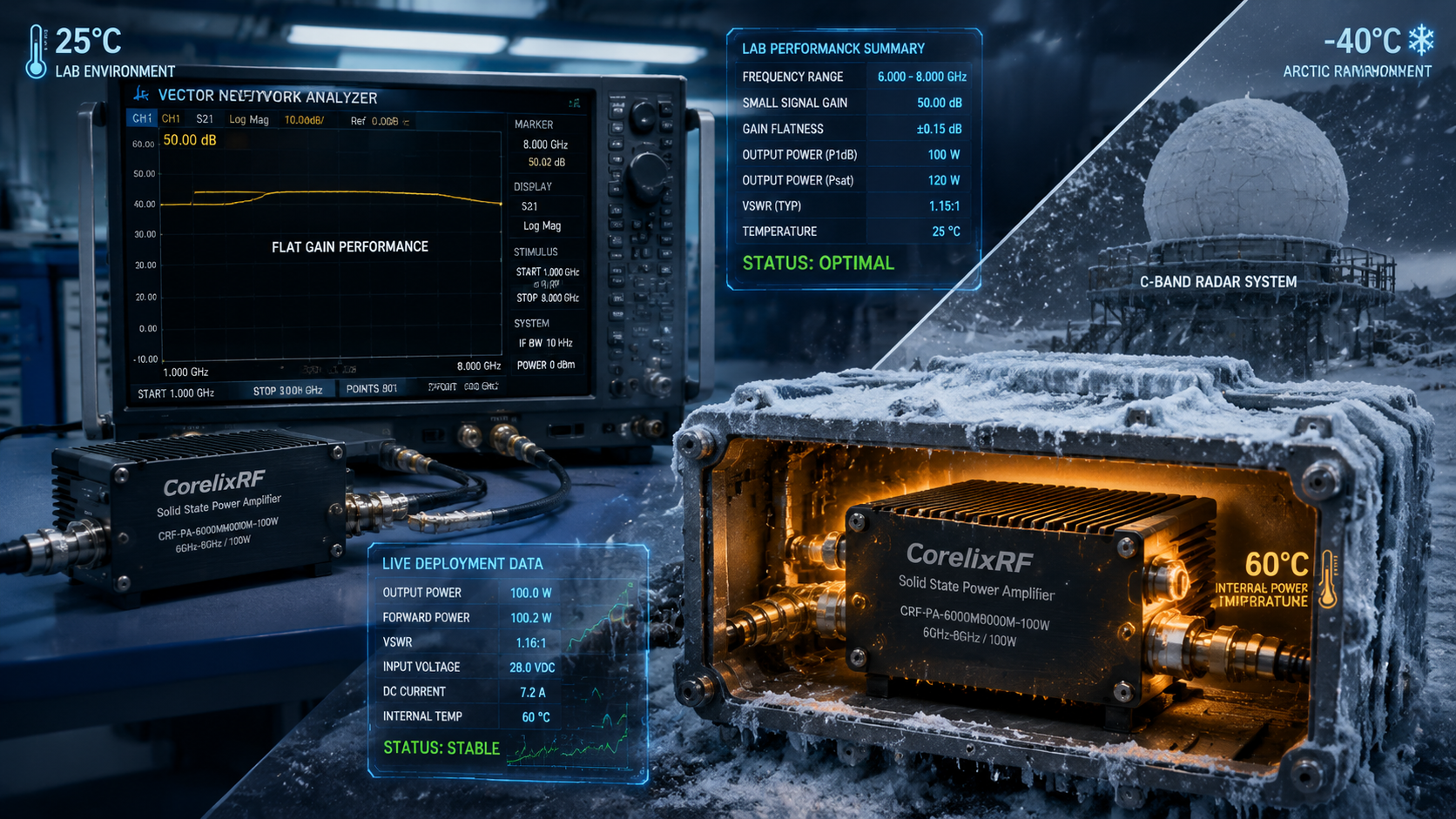
Engineers face severe thermal constraints when deploying wideband tracking systems near Arctic circles. You calibrate hardware inside a temperature-controlled facility. Everything works perfectly at room temperature. Then field deployment happens abruptly. Sub-zero ambient air forces integrators into sealing chassis units tightly against snow ingress. Internal component heat gets trapped instantly. This trapped thermal energy drives internal enclosure measurements above sixty degrees Celsius rapidly. Radar screen targets begin fading unexpectedly. You experience a massive drop in return signal amplitude. Here is the harsh reality. Uncontrolled internal heat shifts amplifier transconductance drastically. We offer engineering truth for solving this exact architecture failure. CorelixRF manufactures specific amplification modules for these harsh operational environments. System architects need reliable data for surviving high-latitude deployment.
1. What Triggers Internal Overheating During Sub-Zero Operations?
The Physics Behind Radome Icing and Thermal Trapping
Engineers often observe massive radar degradation across freezing environments. Arctic deployments expose outdoor radomes directly against severe blizzards. Ice accumulation creates thick insulating layers over protective composite materials. Your internal hardware continues generating massive amounts of heat. External freezing temperatures force designers into sealing electronic enclosures completely. Natural convective cooling stops functioning within such tight spatial boundaries. Trapped thermal energy pushes internal module temperatures toward sixty degrees Celsius. You might be wondering about real consequences. This drastic environmental shift destroys calculated performance metrics instantly. Sensitive front-end receivers start showing elevated noise floors on analyzers. Return signals become buried beneath random thermal noise spikes. We see continuous standing wave ratio alarms triggering constantly. Field operators lose tracking capabilities for incoming airborne targets. High-latitude installations demand rigorous thermal dissipation planning. Our factory understands these specific engineering failure mechanisms deeply.
Why Room Temperature Laboratory Baselines Fail On-Site
Designers establish initial performance baselines inside comfortable twenty-five degree laboratories. Technicians calibrate power output parameters using controlled bench environments. Every vector network analyzer shows perfectly flat gain curves initially. These ideal conditions mask severe systemic vulnerabilities completely. Real field installations lack climate control for compact remote cabinets. Amplifier transconductance changes drastically as internal silicon heats up rapidly. What makes this problem so severe? Component specifications vary widely outside standard thermal operating windows. Thermal runaway creates massive impedance mismatches along transmission lines. You will notice high-frequency response dropping off sharply on scopes. Output power drops from one hundred watts down unexpectedly. An entire system loses functional range margin due entirely. We must abandon ideal laboratory assumptions for real field data. Solid state designs require accurate boundary condition modeling.
Recognizing Gain Drift Symptoms on System Scopes
Radar operators stare at display screens showing diminishing target returns. Blinking error lights indicate severe reflection issues happening inside. Maintenance crews measure massive output power drops using directional couplers. Signal analyzers display sudden collapsing behavior across high frequency bands. Here lies a hidden trap. Gain variations distort phase linearity for frequency modulated continuous waves. Accurate ranging becomes physically impossible under these distorted signal conditions. Thermal sensors indicate internal module surfaces reaching fifty degrees Celsius. Your control interface reports active over-temperature protection states triggering repeatedly. System integrators struggle with identifying root causes during field testing. We trace these failures back directly toward poor amplifier selection. Standard commercial modules cannot survive sustained high heat exposure. Real engineering practice requires analyzing raw physical parameter shifts.
Thermal Impact on RF Parameters
| Parameter | 25°C Lab Measurement | 60°C Chassis Condition | Performance Shift |
| Rated Output Power | 100 W | < 70 W | Severe Degradation |
| Input VSWR | 1.5:1 | > 2.5:1 | Impedance Mismatch |
| Gain Flatness | +/- 1.0 dB | +/- 4.0 dB | Curve Collapse |
| Harmonics | -15 dBc | -8 dBc | Increased Distortion |
| System Range | 100 km | 75 km | Link Budget Loss |
2. How Does Thermal Stress Impact Broadband Amplification?
Transistor Level Transconductance Variations
Semiconductor materials exhibit changing electrical properties during thermal cycling. Gallium nitride structures handle heat better than older silicon technologies. High temperatures still alter carrier mobility across semiconductor junctions significantly. Decreased mobility translates directly into lower overall current gain. An amplifier designed for fifty decibel gain drops performance noticeably. This changes everything for radar designers. Operating at sixty degrees Celsius alters device biasing requirements heavily. Fixed bias circuits fail compensating for thermal drift adequately. Transistor output impedance shifts away from fifty ohms gradually. Reflected power increases due entirely towards this mismatch condition. Your cascade stages start pushing preceding driver circuits into saturation. Distortion products rise sharply across your entire operating frequency range. We measure harmonic content creeping above minus ten decibels carrier. Precise thermal compensation networks become mandatory for stable operation.
Matching Network Impedance Shifts Under Load
Passive components inside matching networks experience physical expansion during heating. Printed circuit board substrates change dielectric constants at elevated temperatures. Copper traces alter resistive losses marginally but impact overall performance. These combined physical alterations shift tuned center frequencies noticeably. A circuit matched for six gigahertz drifts downward unexpectedly. Let us examine real physics. Voltage standing wave ratios climb past acceptable two-to-one limits rapidly. Reflected energy returns straight back into sensitive active device junctions. Excess return power generates even more localized junction heating. This destructive cycle ends only with catastrophic device failure eventually. Thermal management must stabilize physical dimensions for specific RF traces. We utilize specialized substrate materials for mitigating dielectric constant drift. High power modules require absolute dimensional stability across environments.
Cascaded Gain Variance and Link Budget Degradation
Multistage amplifier architectures multiply single stage errors continuously. A minor drop in driver gain forces final stages harder. Final power transistors fail reaching full saturated output capability. Your overall link budget loses several decibels of necessary margin. Radar detection range shrinks proportionally according towards radar equations. Why does this matter fundamentally? Operators cannot track distant fast moving targets accurately anymore. Signal processors receive weakened returns buried under thermal noise. False alarm rates increase as thresholds drop lower automatically. System reliability metrics plummet during continuous high-duty cycle operations. Engineering truth dictates maintaining strict gain flatness across entire bands. Our specifications guarantee flatness within plus or minus two point five decibels. We maintain consistent performance metrics regardless of external chassis heating.
CRF-PA-6000M8000M-100W Specifications
| Parameter | Minimum | Typical | Maximum |
| Frequency Range | 6,000 MHz | – | 8,000 MHz |
| Gain | 50 dB | – | – |
| Gain Flatness | -2.5 dB | – | +2.5 dB |
| Rated Output Power | 100 W | – | – |
| Input VSWR | – | – | 2:1 |
3. How Do Engineers Calculate Accurate Link Budgets?
Defining Path Loss over Snow-Covered Terrain
Arctic radar deployments encounter unique electromagnetic propagation environments constantly. Snow accumulation alters ground reflection coefficients across wide operating areas. Surface scattering degrades incoming signal strength for low elevation targets. Path loss equations require modification for these specific icy conditions. Free space calculations ignore severe multi-path interference caused by ice. This creates an unseen barrier. You must allocate extra margin for unpredictable signal fading events. Reflected waves cancel out primary signals causing deep nulls randomly. High-latitude installations demand higher baseline transmitting power levels continuously. One hundred watts becomes a minimum threshold for reliable tracking. Designers specify modules capable of sustained high power delivery exclusively. We analyze these environmental factors during our initial component selection.
Setting Margin for Transmit Power Fluctuations
System integrators build tolerance limits into every radar architecture plan. A transmitter must maintain stable output despite thermal environmental changes. Dropping three decibels cuts radiated power exactly in half instantaneously. Such losses ruin carefully planned detection probability calculations completely. Here is the kicker. Engineers often trust overly optimistic component datasheets blindly during design. They leave inadequate headroom for inevitable high temperature power sagging. A robust system requires amplifiers exhibiting minimal thermal derating characteristics. You need devices operating solidly under high continuous wave loads. Constant power delivery guarantees signal processing algorithms function correctly always. We provide verified test data proving stability under heavy thermal stress. Reliable hardware forms a foundation for accurate link budget planning.
Real-World Component Selection Traps
Purchasing departments often prioritize low cost over proven environmental reliability. Commercial grade components appear attractive for reducing initial production budgets. These cheap alternatives fail spectacularly inside sealed high latitude cabinets. Plastic packaged transistors cannot dissipate heat fast enough externally. Internal die temperatures exceed absolute maximum ratings within minutes easily. What is the real story? Integrators spend thousands dispatching repair crews towards remote snowy sites. Replacing failed field units costs exponentially more than initial hardware. You must specify industrial grade or military compliant modules immediately. Flanged metallic packages offer superior thermal transfer capabilities inherently. We design hardware capable of surviving extreme mechanical and thermal shock. Source factories provide transparency regarding actual material limitations upfront.
Field Testing Instrumentation Guide
| Instrument | Primary Function | Measurement Target | Mandatory Precaution |
| Vector Network Analyzer | Small Signal Gain | S-Parameters / VSWR | Use high power attenuators |
| Spectrum Analyzer | Spectral Purity | Spurious (-60dBc) / Harmonics | Set correct resolution bandwidth |
| Oscilloscope | Time Domain Envelopes | Pulse Droop / Transients | Trigger on control signal |
| Directional Coupler | Power Monitoring | Forward / Reflected Power | Verify coupling factor |
| Thermal Camera | Heat Dissipation | Flange Temperature | Account for metal emissivity |
4. Why Does CRF-PA-6000M8000M-100W Succeed Under Pressure?
GaN Technology Implementation for Stable Output
Advanced gallium nitride substrate forms a core for this amplifier. This material features exceptionally high thermal conductivity compared against silicon. Electrons move faster through wide bandgap structures producing higher efficiency. GaN transistors operate safely at junction temperatures exceeding two hundred degrees. This is where things get interesting. High junction limits translate into massive tolerance for external heat. A sixty degree chassis environment barely challenges these rugged devices. The module delivers a solid one hundred watts continuously. We cover six thousand through eight thousand megahertz flawlessly. C-band radar architectures benefit directly from this wideband high power capability. Designers achieve massive bandwidth without sacrificing peak output amplitude. Gallium nitride provides superior power density for compact physical footprints.
Hardware Circuit Interventions and Built-In Protection
Raw transistor performance requires intelligent control circuitry for field survival. We integrated fast acting directional couplers right at output ports. These sensors monitor forward and reflected waves simultaneously without interruption. Microcontrollers analyze standing wave ratios continuously during active transmission cycles. Ready for the good part? High reflections trigger immediate bias reduction saving costly active devices. Built-in protection covers over-voltage and over-current situations instantaneously. Thermal sensors mounted near transistor flanges monitor physical heat levels. Excessive temperature readings shut down operation before permanent damage occurs. This proactive defense mechanism prevents catastrophic field failures completely. Radar operators receive warning flags through a standard control interface. Our 7W2 connection handles both power delivery and status monitoring.
Reviewing Saturated Power and Gain Flatness Data
Engineers require transparent performance metrics for accurate system level modeling. Our datasheet documents an impressive fifty decibel typical gain parameter. Flatness remains tightly controlled within plus or minus two point five decibels. We plot saturated output power curves across every frequency step. Notice the subtle details. High frequency roll-off gets compensated through precise matching network design. Input signals at zero dBm drive units straight into saturation. Spurious emissions remain suppressed below minus sixty decibels relative carrier. Harmonic distortion stays strictly below minus ten decibels worst case. We test every module thoroughly using fifty ohm system impedances. Reliable continuous operation depends upon these exact verified electrical characteristics. Your engineering team can model performance knowing these parameters remain stable.
Production Line Environmental Testing
| Test Phase | Condition | Duration | Pass Criteria |
| Room Temp Baseline | 25°C, Normal Voltage | 1 Hour | Meets Datasheet Specs |
| High Temp Soak | 60°C, Rated Load | 24 Hours | Power Drop < 0.5dB |
| Thermal Cycling | -40°C to +70°C | 10 Cycles | No Mechanical Failure |
| VSWR Stress | 60°C, Infinite VSWR | 5 Minutes | Protection Triggers Safely |
| Continuous Burn-In | 50°C, Full Output | 72 Hours | Zero Performance Drift |
5. How Do Heat Dissipation Dynamics Affect Reliability?
Analyzing 300x360x110 mm Mechanical Layout Features
Physical dimensions dictate overall thermal mass available for heat absorption. Our specific package size offers substantial aluminum housing material volume. A three hundred by three hundred sixty millimeter footprint spreads heat. Large baseplates interface perfectly with external system cooling structures directly. What does this mean for you? Wide surface areas lower thermal resistance between transistor and ambient. Internal components sit spaced apart preventing localized hot spot formation. The one hundred ten millimeter height accommodates internal airflow channels. Heavy duty mounting holes provide secure mechanical coupling during vibration. We machine every chassis using high grade aerospace aluminum blocks. Thick walls prevent flexing while maintaining precise cavity resonance characteristics. Proper mechanical layout forms a basis for long term survival.
Air Cooling Strategies Within Sealed Radar Enclosures
External environment sealing forces reliance upon internal forced air circulation. High speed fans move trapped air across finned amplifier surfaces. This internal air loop distributes concentrated thermal loads more evenly. Heat exchangers located on outer chassis walls transfer energy outside. Here is a key insight. Airflow routing determines whether an amplifier survives continuous duty cycles. We tune our module shape for minimum aerodynamic flow resistance. Smooth external surfaces prevent turbulent dead zones from trapping heat. Intake fans push cool air directly over active RF sections. Exhaust ports channel hot air away from sensitive driver stages. Proper thermal modeling software simulates these exact internal fluid dynamics. Radar integrators must prioritize internal airflow pathways during initial drafting.
Correlating DC Supply Drops with Thermal Runaway
High temperature environments impact power supply efficiency alongside RF modules. A twenty eight volt direct current source experiences voltage sagging. Copper supply cables increase resistance as ambient cabinet heat rises. Dropping supply voltages force amplifiers into drawing higher current levels. Why should engineers care? Increased current draw generates additional resistive heating along internal traces. This vicious cycle accelerates thermal runaway conditions inside sealed enclosures. We design our bias networks holding stable performance despite supply fluctuations. Current limiters prevent catastrophic failure during severe voltage drop events. System architects must specify heavy gauge wiring for power delivery. Proper decoupling capacitors maintain transient voltage stability under heavy loads. Engineering truth requires addressing complete system level power dynamics thoroughly.
Actionable Procurement Checklist
| Action Item | Responsible Party | Expected Outcome | Target Metric |
| Thermal Modeling | System Architect | Chassis Temp Profile | < 60°C internal |
| Link Budget Update | RF Engineer | Range Verification | 3dB Margin added |
| Component Selection | Procurement | Order CRF-PA-6000M8000M-100W | 100W at C-Band |
| Factory Consultation | Lead Designer | Customization Spec | VNA Data Confirmed |
| Quality Audit | QA Manager | Document Verification | ISO 9001 / GJB 9001C |
6. Which Instrument Configurations Verify Performance?
Vector Network Analyzer Setup for Baselines
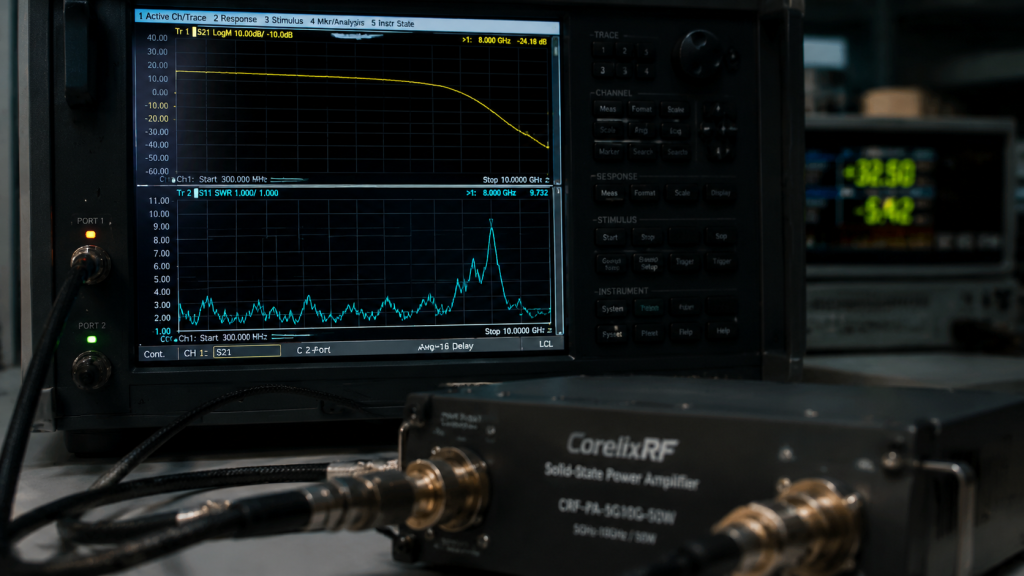
Field engineers deploy vector network analyzers for initial system checks. You must calibrate these expensive tools accurately before taking measurements. Temperature controlled test cables prevent phase errors during calibration sweeps. Connect an input SMA-Female port securely towards your analyzer source. Consider this practical advice. Route output N-Female connectors through high power attenuators before measuring. Direct connections will destroy sensitive network analyzer receiver ports instantly. Sweeping across six thousand through eight thousand megahertz reveals resonances. We observe gain flatness directly matching factory supplied data sheets. VNA displays show exact input return loss indicating matching quality. A stable two to one VSWR confirms proper antenna integration. These baseline sweeps provide a reference against future thermal degradation.
Tracking Spurious Emissions at -60 dBc
Radar systems require pristine spectral purity for avoiding interference issues. Unwanted spurious signals mask real targets or trigger false alarms. Spectrum analyzers sweep wide bands looking for these hidden tones. Our design guarantees spurious outputs remain below minus sixty decibels. What makes this challenging? High power nonlinear devices naturally generate intermodulation distortion products constantly. Poor circuit layout radiates energy causing feedback loops and oscillation. We utilize multiple shielding cavities isolating different amplification stages completely. Feedthrough capacitors filter noise leaving via direct current supply lines. Clean output spectrums guarantee compliance with strict aviation control regulations. Engineers must set analyzer resolution bandwidths properly for accurate detection. A low noise floor reveals true spectral performance accurately always.
Oscilloscope Methods for Transient Output Verification
Continuous wave performance tells only partial stories for pulsed radars. Oscilloscopes capture fast transient behaviors occurring during initial signal bursts. Fast switching power supplies cause voltage ringing impacting RF envelopes. You must monitor detected RF envelopes alongside bias control voltages. Let me point this out. Droop across a long pulse indicates inadequate local energy storage. We place massive capacitance near high power GaN transistor drains. This stored energy supports instantaneous current demands during pulse turn-on. Oscilloscope traces verify stable power levels throughout entire transmission periods. Amplitude variations during pulses ruin Doppler processing algorithms completely today. Field technicians rely upon sharp oscilloscope triggers for capturing anomalies. Precision measurements validate true engineering robustness regarding our hardware products.
7. How Does VSWR Protection Save RF Front-Ends?
Antenna Mismatch Events from Ice Buildup
High-latitude radar antennas suffer continuous exposure against freezing rain storms. Ice changes physical dimensions for finely tuned radiating metallic elements. This added dielectric layer alters free space impedance matching drastically. Energy refuses radiating outward returning instead along transmission feed lines. You cannot ignore this. Reflected power travels backward hitting your final amplifier stages hard. A one hundred watt signal returning causes massive voltage spikes. Unprotected amplifiers explode under these severe high voltage standing waves. We see cracked transistor packages scattered across poorly designed systems. Ice mitigation strategies include heated radomes consuming massive electrical power. Passive hardware protection remains absolutely necessary for surviving unexpected icing. Our robust amplifier modules handle these hostile environmental conditions seamlessly.
The Input VSWR Threshold Explanation
Our specification limits acceptable input standing wave ratios strictly. A maximum two to one ratio defines proper source matching. Driver stages preceding our module expect stable fifty ohm loads. Fluctuating input impedances alter preceding stage gain and linearity parameters. Here is a different angle. We incorporate internal isolators for stabilizing input port reflection coefficients. These ferromagnetic devices route reflected input energy into dummy loads. Your driver circuit sees perfect fifty ohm matches continuously always. We maintain system stability even when cascading multiple amplifier blocks. Field technicians measuring input return loss verify our matching claims. Solid input matching prevents low frequency oscillation issues from emerging. Engineers trust these predictable interface parameters during complex system drafting.
Over-Voltage and Over-Current Safety Triggers
Harsh environments cause unpredictable power grid fluctuations constantly during storms. Lightning strikes nearby induce massive voltage spikes along supply cables. Our internal circuitry monitors twenty eight volt rails for surges. Over-voltage protection disconnects sensitive semiconductor drains instantly during high transients. Why does this matter? Excessive voltage punctures thin semiconductor layers causing permanent short circuits. Simultaneously current monitors watch for abnormal consumption pointing towards faults. A sudden shorted antenna causes massive current spikes across transistors. Our current limiting limits damage keeping overall system architectures safe. Operators reset these fault conditions remotely after clearing external problems. We prioritize equipment survival above continuous operation during catastrophic events. This defensive engineering philosophy saves integrators massive replacement hardware costs.
8. What Are the True Production Line Testing Methodologies?
Replicating 60°C Operating Temperatures in Chamber
Factory acceptance testing requires validating performance under extreme simulated conditions. We place complete amplifier modules inside programmable environmental heating chambers. Technicians raise ambient temperatures slowly towards sixty degrees Celsius targets. Equipment runs at full saturated output power during thermal soaking. This changes the game. We monitor RF output parameters continuously looking for unexpected degradation. Thermal cameras identify localized hot spots requiring mechanical layout adjustments. Only units surviving extended high heat exposure leave our factory. Standard bench testing simply cannot guarantee reliability for Arctic deployments. We expose hidden soldering defects through repetitive thermal cycling stresses. Our rigorous validation process guarantees field longevity for every unit. Customers receive hardware fully vetted against harsh operational realities upfront.
Maintaining 50dB Gain Uniformity Across 400 Units
Large scale radar arrays require hundreds of identical amplifier modules. Phased array systems depend upon precise amplitude matching between channels. Manufacturing variations cause gain discrepancies across different production batch runs. We implement strict quality control procedures holding tight manufacturing tolerances. Let us dig deeper. Automated test benches measure S-parameters for every single production unit. Factory software logs exact gain values across specified frequency bands. We sort modules based upon measured performance matching them perfectly. A fifty decibel target remains consistent across massive production volumes. System integrators building complex arrays appreciate this strict uniformity deeply. We eliminate tedious field tuning procedures through superior manufacturing consistency. Our factory calibration drastically reduces your overall system integration time.
Reading Test Data and Pattern Files
We supply comprehensive documentation accompanying every shipped amplifier module batch. Engineers receive detailed factory test data verifying individual unit performance. These reports include specific frequency response curves plotted under load. Customers review actual measured harmonic levels confirming specification sheet claims. Take this into account. Pattern files provide digital representations matching physical hardware performance exactly. System designers import these files straight into simulation software packages. Accurate modeling prevents costly mistakes during early system architecture phases. You can verify link budgets using real data instead assumptions. Transparency builds trust between component manufacturers and defense contractors ultimately. We stand behind our published electrical characteristics with hard evidence. Our commitment towards engineering truth drives this open data policy.
9. How Do Integrators Plan Procurement for C-Band Radars?
Balancing Lead Times with Customization Options
Military and aerospace projects operate under strict deployment schedule deadlines. Standard off-the-shelf amplifiers rarely meet specific high latitude radar requirements. Customization involves modifying frequency ranges or adding specific control interfaces. Redesigning matching networks requires additional engineering cycles extending delivery times. Here is what matters. We balance rapid prototyping capabilities against massive production volume capacities. Our factory stocks standard GaN transistors anticipating large scale orders. Experienced engineers modify existing baseline architectures rapidly for custom applications. You achieve specific project goals without suffering unacceptable schedule delays. Clear communication regarding technical compromises prevents mismatched expectations during procurement. We guide system architects towards robust hardware configurations during design. Timely delivery regarding necessary components keeps your entire project alive.
Assessing Connector Ratings (SMA-Female to N-Female)
High frequency power transmission requires robust mechanical connection interface standards. Our modules utilize SMA-Female connectors handling low power input signals. These precise interfaces maintain excellent return loss across C-band frequencies. Output ports feature heavy duty N-Female connectors designed for power. This physical detail matters. N-type connectors handle one hundred watts continuously without dielectric melting. A large center pin provides low resistance paths for current. Threaded coupling mechanisms withstand severe mechanical vibration during mobile deployment. Technicians must torque these connections properly preventing passive intermodulation generation. Inferior connectors introduce massive insertion losses ruining overall amplifier efficiency. We select aerospace grade hardware matching our high performance circuitry. Every physical component contributes directly toward final system level reliability.
Aligning ISO 9001 Frameworks for Defense Contracts
Government radar contracts demand rigorous adherence toward international quality standards. ISO 9001 certification proves our manufacturing processes remain strictly controlled. We track every component from incoming inspection through final shipment. Traceability allows identifying specific transistor batches years after initial deployment. You should know this. GJB 9001C compliance demonstrates our capability handling military specification requirements. Defense integrators require this documentation for passing stringent supplier audits. Our quality framework mandates regular calibration for all test instruments. We document non-conformance issues thoroughly implementing corrective actions preventing recurrence. Purchasing from certified source factories minimizes risk for prime contractors. We deliver proven reliability backed by documented quality management systems. This structural integrity forms a reliable basis for long partnerships.
10. What Actionable Steps Secure Your Next Radar Deployment?
Reviewing System Level Tolerances Immediately
Project leaders must evaluate thermal constraints early during architecture planning. Calculate exact heat dissipation requirements based upon worst case scenarios. A sixty degree ambient chassis temperature requires massive cooling margins. Do not rely entirely upon twenty five degree laboratory baselines. Here is your next step. Analyze your link budget assuming a three decibel power loss. Verify whether your radar can still detect targets at maximum. Re-evaluate component datasheets searching for explicit high temperature performance curves. Ask manufacturers hard questions regarding thermal runaway and VSWR protection. A proactive approach prevents catastrophic failures during actual field deployment. Engineering truth requires facing physical limitations directly without optimistic assumptions. Start mapping your thermal boundaries today for a secure tomorrow.
Contacting Factory Application Support Direct
Skip intermediate distributors and connect straight with source factory engineers. We possess twenty years experience troubleshooting complex RF power issues. Our team analyzes your specific radome icing and thermal trapping. Send us your exact system block diagrams for detailed review. Why is this beneficial? We identify mismatched impedance interfaces and recommend proper isolation techniques. Factory support provides custom CAD files for mechanical thermal modeling. You gain access towards proprietary test data unavailable through catalogs. We help define custom options matching your unique project requirements. Direct communication eliminates misunderstandings saving massive amounts of engineering time. Let our experts handle heavy amplification challenges while you design. Collaboration breeds robust hardware architectures capable of surviving any environment.
Finalizing Architecture Based on Engineering Truth
Solid state amplifier selection defines ultimate radar system field performance. The CRF-PA-6000M8000M-100W module provides verified stability under extreme thermal stress. GaN technology combined with robust mechanical design solves overheating completely. We guarantee fifty decibel gain and comprehensive built-in protection features. Make the right choice. Base your final architecture upon proven physics and hard data. Ignore marketing fluff promising impossible performance without adequate thermal mass. Real engineers build systems capable of surviving sixty degree environments. Our source factory delivers exactly what high-latitude radar deployments demand. Choose reliability, choose verified performance, and secure your long range tracking. Let us build hardware powering your next remote tracking deployment. System success depends upon acknowledging and respecting these physical realities.
Reviewing engineering analysis proves that surviving sixty degree ambient chassis temperatures requires strict adherence toward fundamental physics. The CRF-PA-6000M8000M-100W tackles gain drift directly through GaN implementation and robust thermal layout. Secure your high-latitude radar performance by contacting CorelixRF for detailed component evaluation today. Review our comprehensive datasheet testing parameters and secure reliable hardware.
FAQ Section
- Q1: What is the CRF-PA-6000M8000M-100W?The CRF-PA-6000M8000M-100W represents a wideband RF power amplifier module. We manufacture this device specifically for C-band radar applications. It delivers one hundred watts continuously across six through eight gigahertz.
- Q2: How does internal thermal trapping work?Sealed radar enclosures prevent natural convective cooling from occurring. Heat generated by internal electronics becomes trapped inside tight spaces. This raises ambient chassis temperatures dramatically toward sixty degrees Celsius.
- Q3: Why do amplifiers lose power at high temperatures?Semiconductor materials experience decreased carrier mobility during extreme thermal heating. This physical change lowers overall transistor transconductance significantly. A resulting gain drop causes massive output power degradation.
- Q4: How does VSWR protection save the radar system?Ice accumulation on antennas creates severe impedance mismatches instantly. Our built-in protection monitors reflected power and reduces bias currents. This prevents high voltage standing waves from destroying active transistors.
- Q5: Why specify GaN technology for high-latitude deployments?Gallium nitride handles massive internal heat better than older technologies. It provides superior thermal conductivity and higher junction temperature limits. This guarantees stable power delivery despite severe external environmental shifts.