
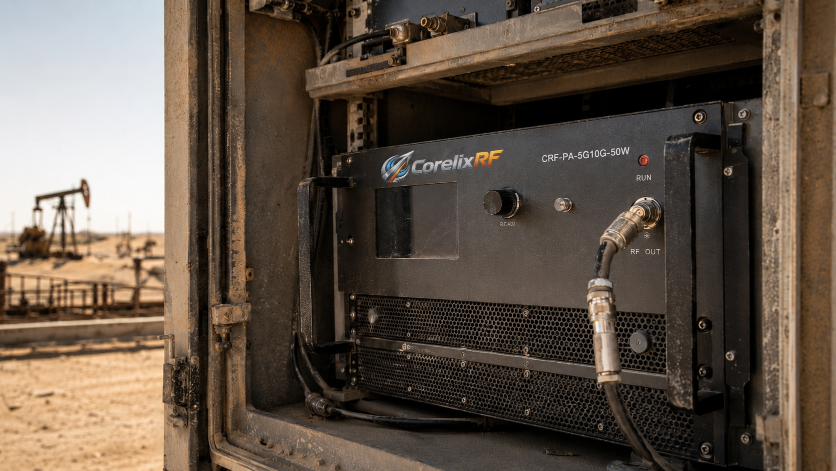
System integrators face massive challenges deploying telemetry equipment within harsh Middle East oilfields. Equipment reliability remains paramount for continuous data transmission across remote desert locations. We present robust architecture solutions combating severe gain thermal drift inside sealed outdoor cabinets. CorelixRF relies on twenty years of field troubleshooting experience crafting rugged hardware. Our factory designs specialized RF power amplifiers engineered explicitly for extreme industrial applications. What’s the real story? Laboratory tests simply cannot replicate brutal sixty-degree Celsius enclosure temperatures found onsite. Standard testing parameters hide catastrophic vulnerabilities within communication link budgets. Engineers require factual physical data rather than optimistic software simulations when designing critical infrastructure. We deliver engineering truth through precise microwave component selection and superior thermal dissipation strategies. Proper architectural planning prevents sudden network blackouts during peak afternoon heat waves.
Map thermal drift risk to rugged RF amplifier selection
For outdoor or high-temperature RF amplifier projects, CorelixRF can review thermal derating, gain flatness, cooling path, protection logic and factory acceptance evidence before selecting a platform.
1. What Causes System Failures In Middle East Oilfields?
● High ambient temperature effects
● Link budget collapse
● Telemetry blackout
Middle East oilfields present unforgiving environments for high-power radio frequency equipment. Sealed metal cabinets sit directly under intense solar radiation without natural shading. These enclosures protect sensitive electronics from pervasive sandstorms damaging delicate internal structures. However this isolation traps immense heat generated by active communication components. Internal ambient temperatures routinely exceed sixty degrees Celsius during daylight hours. Such extreme heat forces semiconductor devices far beyond their intended operating ranges. Thermal runaway becomes a constant threat for poorly designed amplifier stages. This is where it gets interesting Engineers often rely upon twenty-five degree Celsius baseline datasheets during initial system planning. This fundamental mismatch between lab conditions and actual desert deployment guarantees eventual hardware failure. Heat accumulation physically alters electrical properties across entire transmitter chains.
Field technicians frequently encounter sudden telemetry blackouts without prior warning signals. Control rooms lose connection with remote wellheads monitoring critical fluid pressures. Maintenance crews arrive onsite finding unresponsive base stations displaying hardware fault codes. Diagnostic instruments reveal collapsed transmission curves resembling total component destruction. The root cause traces directly back toward inadequate thermal architecture managing power dissipation. High temperatures alter substrate dielectric constants within printed circuit boards physically. This physical change shifts resonant frequencies away from perfectly tuned carrier bands. Gain thermal drift completely destroys carefully calculated link margins established during design phases. We have seen countless commercial off-the-shelf amplifiers fail within weeks under these conditions. Reliable operation demands purpose-built equipment featuring superior heat extraction methodologies.
Environmental Impact On Telemetry Equipment
| Parameter | Laboratory Testing Environment | Middle East Oilfield Environment |
| Ambient Air Temperature | Controlled twenty-five degrees Celsius | Unregulated sixty degrees Celsius |
| Contamination Risk | Clean room atmospheric conditions | Severe sandstorm particulate exposure |
| Enclosure Airflow | Active unrestricted cooling fans | Sealed cabinets with restricted ventilation |
| Component Thermal Stress | Minimal junction temperature elevation | Maximum sustained junction temperature loading |
| Expected Reliability | Continuous uninterrupted signal transmission | High probability of hardware failure |
2. How Does Enclosure Heat Impact RF Amplifiers?
● Semiconductor thermal dynamics
● Transistor junction temperature
● Output power degradation
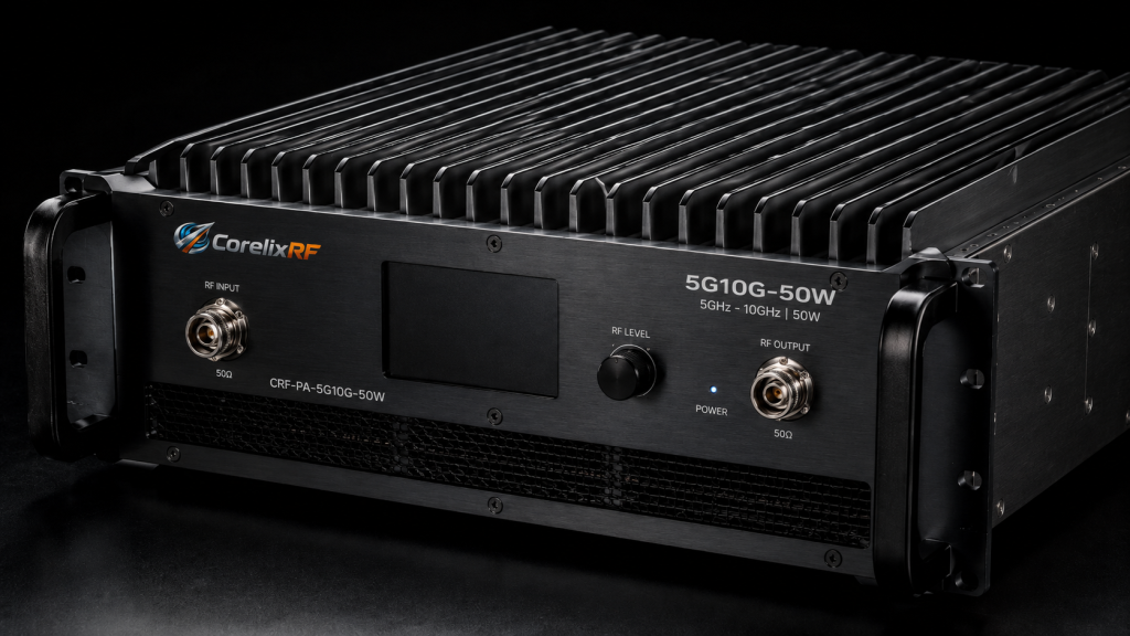
Radio frequency amplifiers generate massive waste heat during regular operation. Efficiency ratings dictate how much direct current converts into useful output power. Remaining energy transforms instantly into destructive thermal loads requiring immediate extraction. Fifty watts of pure microwave energy might require dissipating another hundred watts thermally. Transistor junction temperatures climb rapidly when heat sinks cannot reject energy fast enough. Silicon LDMOS or Gallium Nitride devices possess absolute maximum temperature thresholds. Exceeding these limits causes immediate irreversible physical damage at a microscopic level. You might be wondering: what happens right before catastrophic semiconductor failure occurs? Engineers observe severe output power degradation as internal device resistance increases massively.
Thermal dynamics dictate that charge carrier mobility decreases drastically as heat rises. This physical phenomenon reduces absolute amplification capability across active transistor stages. An amplifier pushing fifty watts at twenty-five degrees might only output thirty watts later. System link budgets collapse when transmission strength falls below critical reception thresholds. Elevated temperatures increase thermal noise floor levels across receiver front ends. This combination of reduced transmission strength and increased noise guarantees data packet loss. Real world troubleshooting often involves connecting spectrum analyzers directly onto faulty field nodes. Technicians watch carrier signals shrink steadily while ambient heat bakes their equipment racks. We engineer CorelixRF products specifically anticipating these brutal thermal degradation curves. Proper architecture must account for worst-case environmental conditions from day one.
3. Why Do Lab Tests Fail Predicting Field Performance?
● Controlled environments vs reality
● Misleading thermal dissipation models
● False confidence during validation
System integrators often evaluate new hardware inside climate-controlled engineering laboratories. These environments maintain perfectly regulated twenty-five degree Celsius ambient air streams. Fans push cool air aggressively across exposed component heat sinks without restriction. Such ideal conditions produce excellent performance metrics on standard test reports. Designers build complete link budgets assuming these optimistic baseline figures remain constant permanently. But here’s the kicker nature completely ignores controlled laboratory validation protocols during actual deployment. Real oilfield enclosures lack generous airflow paths found across open test benches. Dust filters clog quickly with fine sand particles reducing cooling fan efficiency dramatically. Stagnant hot air recirculates inside sealed metal boxes cooking internal circuit boards continuously.
Misleading thermal models create false confidence among project management teams during procurement. Software simulations frequently assume perfect thermal interfaces between transistors and metal chassis parts. Reality introduces microscopic air gaps and degraded thermal paste slowing heat transfer rates. These small discrepancies compound exponentially under sustained maximum power output conditions. We routinely analyze failed competitor modules returning from harsh desert environments. Their internal logs show rapid overheating cycles completely missing from initial factory documentation. Engineering truth demands validating hardware under actual stressful environmental profiles before installation. CorelixRF utilizes environmental test chambers pushing equipment beyond sixty degrees Celsius routinely. Our specifications reflect achievable performance metrics under severe operational duress consistently.
Testing Environment Discrepancies
| Validation Aspect | Laboratory Simulation Assumption | Actual Oilfield Reality |
| Air Circulation Volume | Unrestricted high velocity cooling air | Stagnant recirculated hot air pockets |
| Thermal Interface Quality | Perfect microscopic heat sink contact | Degraded paste with sand contamination |
| Power Supply Voltage | Stable regulated direct current source | Fluctuating generator power with spikes |
| Link Budget Calculation | Based on ideal ambient temperature | Severely degraded by thermal variance |
| Hardware Lifespan | Many years of reliable operation | Months before catastrophic component failure |
4. What Is Gain Thermal Drift In Power Amplifiers?
● Definition of gain fluctuations
● S-parameter shifts over temperature
● Matching network detuning
Gain thermal drift represents a critical parameter degradation mechanism within microwave systems. Amplification circuits rely on precise electrical characteristics across multiple cascaded gain stages. Transistor transconductance changes dynamically based upon physical junction temperature variations. A temperature increase typically reduces semiconductor gain capability in a measurable linear fashion. This means an amplifier providing forty-seven decibels might drop several decibels unexpectedly. Ready for the good part? Proper hardware design can compensate for these natural physical tendencies automatically. Engineers implement advanced bias tracking networks monitoring temperature and adjusting voltages accordingly. However cheaper commercial units skip these critical compensation circuits entirely saving manufacturing costs.
S-parameters define how microwave energy moves through complex matching networks. These parameters shift dramatically when extreme heat alters substrate dielectric properties physically. Copper traces expand slightly changing critical impedance values along transmission lines. Such variations cause severe detuning across narrow frequency bands during operation. Reflected energy increases drastically as matching networks drift away from fifty ohms. This reflected power converts into additional heat compounding existing thermal management problems. Technicians using vector network analyzers field-test these drifted modules regularly. They witness transmission curves completely sagging across upper frequency ranges under thermal load. Solving this requires utilizing specialized high-frequency laminates resisting temperature-induced dielectric shifts.
5. How Does Thermal Drift Disrupt Telemetry Systems?
● Signal-to-noise ratio reduction
● Demodulation errors
● Continuous wave distortion
Oilfield telemetry systems require stable transmission characteristics for accurate data demodulation. Phase modulation schemes pack dense information into extremely narrow frequency channels. These complex digital formats demand highly linear amplification without amplitude or phase distortion. Gain thermal drift introduces unpredictable amplitude variations corrupting transmitted symbols actively. Receivers struggle distinguishing intended data points from random thermal noise fluctuations. This signal-to-noise ratio reduction causes immediate increases in bit error rates. Control systems reject corrupted packets requiring constant retransmission routines slowing network traffic. Here’s the deal: continuous retransmissions force amplifiers into extended high-power duty cycles. These prolonged transmitting states prevent hardware from entering necessary thermal cooldown periods entirely.
These extended transmission periods generate even more waste heat worsening initial problems. Modems eventually drop connections entirely when error correction algorithms fail completely. Remote automated valves might remain stuck open because command signals become unreadable. Continuous wave signals suffer severe distortion when active components heat unevenly. AM-to-PM conversion effects become prominent causing severe phase noise degradation. Engineers diagnosing these failures often blame poor antenna alignment initially. True root causes usually point toward uncompensated thermal drift inside power amplifier modules. Robust system architecture prevents these cascading failure loops through intelligent thermal management. We build hardware capable of maintaining phase linearity despite massive ambient temperature swings.
Telemetry Degradation Sequence
| Degradation Stage | Physical Mechanism Occurring | System Level Symptom |
| Initial Heating | Transistor junction temperature rises | Minor reduction in peak output power |
| S-Parameter Shift | Substrate dielectric constant alters | Impedance mismatch and rising VSWR |
| Gain Compression | Amplifier linearity degrades drastically | Signal distortion and phase noise |
| SNR Collapse | Receiver cannot distinguish data symbols | Massive increase in bit error rates |
| Network Failure | Modem loses synchronization completely | Total loss of remote telemetry data |
6. What Architecture Flaws Lead To Dissipation Failure?
● Improper heat sink sizing
● Poor airflow paths
● Thermal bottlenecking
Poor architectural decisions during early design phases guarantee eventual thermal dissipation failures. Many system integrators prioritize compact form factors over adequate thermal management strategies. Squeezing high-power modules into tiny enclosures restricts critical airflow paths drastically. Improper heat sink sizing remains a very common engineering mistake across industries. Fins spaced too closely together trap dust and restrict natural convection currents. This creates localized hot spots directly beneath expensive semiconductor devices. What’s the real story? Thermal bottlenecking occurs when heat cannot move away from components fast enough. Thermal bottlenecks destroy expensive semiconductor lifespan metrics faster than any other environmental factor encountered onsite.
Engineers must analyze entire thermal resistance paths from transistor junctions toward ambient air. Thick layers of cheap thermal grease often act as unintended insulators. Using inferior aluminum alloys instead of high-grade copper baseplates slows heat spreading. Cooling fans placed improperly create dead zones where hot air stagnates permanently. Field deployment reveals these architectural flaws rapidly under intense Middle East solar loads. The CorelixRF factory avoids these traps through rigorous mechanical engineering standards. Our three rack unit chassis provides massive volume for proper internal air circulation. We utilize massive forced air cooling directed precisely across custom milled heat sink profiles continuously.
7. How Can Engineers Optimize Link Budgets For Heat?
● Calculating thermal margins
● Component derating strategies
● Active compensation techniques
Link budget optimization requires acknowledging harsh environmental realities during mathematical modeling. Smart engineers never assume laboratory performance data translates directly into field success. Calculating thermal margins involves subtracting expected temperature-induced losses from ideal transmission figures. If an amplifier loses three decibels at sixty degrees incorporate that deficit early. Component derating strategies force designers into selecting parts exceeding minimum system requirements. Operating a hundred-watt amplifier at fifty watts greatly improves long-term reliability. This practice reduces thermal stress and prevents running active devices near compression points. This is where it gets interesting active compensation techniques provide another layer of architectural defense.
Modern robust designs include internal microcontrollers monitoring chassis temperatures continuously. These controllers adjust gate bias voltages maintaining constant gain profiles automatically. We implement advanced leveling loops preventing output power fluctuations despite environmental changes. System integrators should always review maximum VSWR tolerance specifications carefully. Extreme heat causes antenna characteristics to drift creating severe impedance mismatches occasionally. Amplifiers lacking proper isolation will self-destruct when facing high reflected power levels. Designing conservative link budgets guarantees networks remain operational during worst-case summer afternoons. Our engineering team provides detailed thermal performance charts helping clients calculate accurate operating margins confidently. We insist upon physical hardware testing validating every theoretical mathematical calculation performed during design phases.
Link Budget Optimization Strategies
| Optimization Strategy | Implementation Method | Resulting System Benefit |
| Thermal Margin Buffer | Subtract 3dB from ideal transmission power | Prevents unexpected signal loss during heat waves |
| Component Derating | Run hardware at fifty percent maximum capacity | Drastically lowers transistor junction temperatures |
| Active Bias Tracking | Microcontroller adjusts voltage based on heat | Maintains flat gain response across temperature extremes |
| VSWR Protection | Install rugged isolators on RF output ports | Prevents amplifier destruction from reflected power |
| Advanced Materials | Use low thermal expansion high-frequency PCBs | Keeps matching networks tuned at sixty degrees Celsius |
8. What Makes CorelixRF CRF-PA-7000M9000M-50W Different?
● 7000-9000 MHz stability
● Forced air cooling design
● Built-in VSWR protection
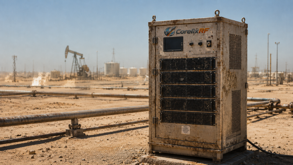
The CRF-PA-7000M9000M-50W represents thirty years of dedicated radio frequency manufacturing expertise. This specific wideband power amplifier operates flawlessly between seven thousand and nine thousand megahertz. We engineer this unit specifically for demanding test measurement and critical communication roles. Delivering fifty watts of rated output power requires exceptional thermal architecture fundamentally. The rugged nineteen-inch three-rack-unit package size provides substantial mass for continuous heat dissipation. You might be wondering: how does this model survive Middle East oilfield conditions? Our forced air cooling method pushes massive volumes of cool air through optimized metallic channels endlessly. This direct cooling approach prevents stagnant hot zones from forming around sensitive LDMOS transistor packages.
We integrate complete built-in protection mechanisms guarding against catastrophic field failures. Over-voltage and over-temperature circuits monitor hardware health hundreds of times per second. The system shuts down gracefully before physical semiconductor damage can ever occur. Extreme VSWR protection guarantees survival even if antenna cables become severed completely. Over-drive protection prevents accidental input signal spikes from destroying sensitive pre-amplifier stages. We utilize standard N-Female connectors providing robust mechanical connections resisting severe environmental vibrations. Engineers can monitor device status remotely utilizing standard RS485 or LAN networking interfaces. This level of architectural ruggedness defines true engineering truth for heavy industrial microwave applications.
9. How Does This Amplifier Maintain Gain At 50°C?
● Hardware circuit adjustments
● High-frequency material selection
● Mechanical structure benefits
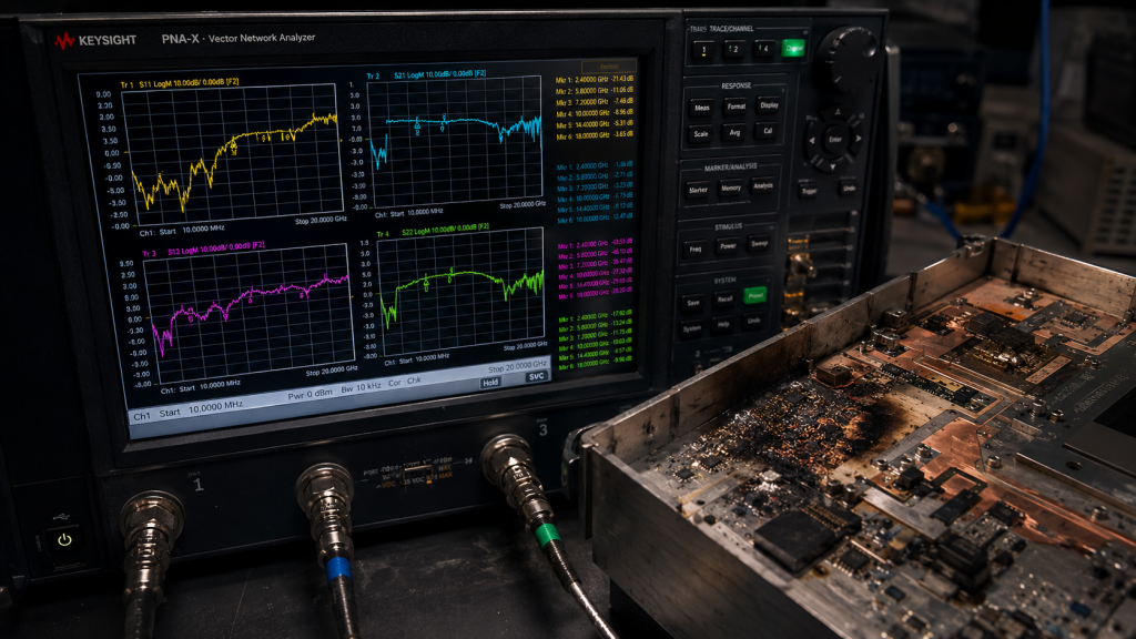
Maintaining forty-seven decibels of gain at elevated temperatures requires sophisticated internal engineering. Standard amplifiers exhibit massive gain droop when ambient heat approaches fifty degrees Celsius. Our CRF-PA-7000M9000M-50W maintains an impressive gain flatness within plus or minus four decibels. This stability originates from meticulous hardware circuit adjustments during the manufacturing process. We employ specialized temperature compensation networks countering natural semiconductor gain degradation automatically. Here’s the deal: material science plays a massive role in our structural success. High frequency signal fidelity demands utilizing advanced substrates rather than standard cheap fiberglass circuit boards. We source specific dielectric materials proven capable of surviving extreme thermal cycling without physical degradation.
We select premium high-frequency laminates featuring extremely stable dielectric constants across temperature ranges. This prevents critical matching networks from detuning when the internal chassis gets very hot. RF energy transfers efficiently toward the output connector rather than converting into waste heat. The mechanical structure features a massive precision-milled aluminum baseplate for maximum thermal transfer. Heat moves instantly away from active device junctions toward external cooling fins. We guarantee harmonics remain below minus fifteen decibels under continuous full power operation. Spurious emissions stay strictly below minus sixty decibels securing clean spectrum environments. Such rigorous specifications prove our commitment toward delivering uncompromised industrial microwave hardware performance.
CRF-PA-7000M9000M-50W Key Specifications
| Technical Parameter | Specification Value | Engineering Significance |
| Frequency Range | 7,000 to 9,000 MHz | Covers critical wideband communication and radar bands |
| Rated Output Power | 50 W | Provides massive signal strength for long distance telemetry |
| Gain / Flatness | 47 dB / ±4 dB | Ensures stable amplification across entire frequency spectrum |
| Built-in Protection | Over-voltage, temp, VSWR | Prevents catastrophic hardware failure in harsh environments |
| Cooling Method | Forced air cooling | Extracts massive thermal loads from continuous operation |
10. How Can Integrators Implement This Solution?
● Form factor integration
● Control interface setup
● Field deployment procedures
System integrators require straightforward deployment procedures when upgrading critical oilfield communication infrastructure. The CRF-PA-7000M9000M-50W utilizes a standard nineteen-inch form factor easing field cabinet installation. This three-rack-unit size slides perfectly into existing telecommunication enclosures without expensive mechanical modifications. We supply complete mechanical outline drawings guaranteeing perfectly planned physical integration ahead of time. The AC 220 V power supply requirement matches standard industrial generator outputs easily. Ready for the good part? Remote management integration drastically reduces expensive field maintenance visits. Network administrators can query internal sensor data continuously without dispatching technicians across remote deserts. This remote visibility provides early warning indicators regarding potential thermal issues before complete system failure happens.
Engineers connect directly into the amplifier brain using standard RS485 or LAN interfaces. Control rooms monitor forward power and device temperature metrics from thousands of miles away. Field deployment procedures mandate checking input VSWR remaining below a two-to-one ratio strictly. Technicians must ensure zero dBm maximum input power preventing sensitive front-end overdrive conditions. We provide detailed test data and pattern files facilitating rapid project review cycles. Our ISO 9001 and GJB 9001C quality frameworks guarantee consistent performance across large manufacturing batches. Adopting this rugged architecture eliminates crippling effects regarding severe gain thermal drift permanently. We stand behind our published data sheets guaranteeing every unit performs exactly as specified under extreme conditions.
Harsh Middle East oilfields destroy poorly designed radio frequency communication equipment rapidly. Extreme enclosure heat causes severe gain thermal drift collapsing critical telemetry link budgets completely. The CorelixRF CRF-PA-7000M9000M-50W solves this through superior thermal architecture and rugged hardware component selection. System integrators must prioritize factual engineering truth over optimistic software simulations during procurement phases. Ignoring extreme environmental factors during early design stages guarantees catastrophic field failures later. We provide transparent test data proving our amplifiers maintain stable performance despite severe thermal stress. Please contact our technical sales team immediately for detailed product datasheets and custom system integration support. Let us help you build unbreakable wireless networks capable of surviving the harshest deserts on earth.
Q1: What is gain thermal drift? Gain thermal drift refers to unpredictable amplification fluctuations caused by extreme temperature variations altering semiconductor physical properties. When ambient heat rises significantly inside sealed equipment enclosures, active radio frequency transistors lose their ability transferring energy efficiently. This natural physical degradation causes total output power levels dropping off steadily over time. Extreme heat physically alters printed circuit board dielectric constants causing impedance mismatches across tuned networks. These combined effects destroy carefully calculated link margins leaving system integrators facing unexpected network blackouts. Designing robust hardware requires implementing active bias compensation circuits countering these destructive temperature shifts automatically. We build our equipment specifically resisting these exact failure mechanisms ensuring reliable operation continuously.
Q2: How does 60°C enclosure heat impact RF amplifiers? Extreme heat decreases transistor efficiency while simultaneously detuning high-frequency matching networks causing severe output power degradation. Sixty degrees Celsius ambient air completely prevents standard heat sinks from extracting waste energy away from semiconductor junctions. These elevated temperatures push silicon and gallium nitride devices dangerously close toward their absolute maximum thermal limits. Prolonged exposure causes irreversible microscopic damage reducing overall component lifespan metrics dramatically. Signal-to-noise ratios collapse as thermal noise floors rise masking intended phase modulated telemetry data packets. Technicians often arrive onsite finding completely unresponsive base stations displaying critical hardware fault codes. CorelixRF architecture prevents this utilizing massive precision-milled aluminum baseplates transferring heat rapidly into forced air streams.
Q3: Why do lab tests fail predicting field performance? Laboratory environments provide perfect unrestricted airflow which completely fails simulating stagnant hot air inside sealed desert enclosures. Engineers often rely upon twenty-five degree Celsius baseline datasheets containing highly optimistic performance metrics during initial procurement phases. These controlled testing conditions never account for clogged dust filters restricting cooling fans after severe sandstorms hit. Software simulations frequently assume perfect thermal interfaces completely ignoring microscopic air gaps degrading heat transfer rates realistically. Real world deployment exposes these architectural flaws rapidly causing cascading hardware failures across remote monitoring networks. We validate all CorelixRF products inside extreme environmental chambers pushing hardware beyond realistic limits purposely. This provides factual engineering truth guaranteeing our amplifiers survive actual brutal oilfield deployments without fail.
Q4: What makes CorelixRF CRF-PA-7000M9000M-50W different? This specific model features rugged forced air cooling architecture combined with massive built-in protection against VSWR faults. We engineered this nineteen-inch three-rack-unit system explicitly targeting demanding test measurement and critical communication roles within harsh environments. It maintains forty-seven decibels of stable gain between seven thousand and nine thousand megahertz despite extreme ambient heat. Our factory implements specialized temperature compensation networks countering natural semiconductor gain degradation automatically during continuous operation. Built-in microcontrollers monitor over-voltage and over-temperature parameters shutting down active stages gracefully preventing permanent physical damage. We utilize premium high-frequency laminates resisting temperature-induced dielectric shifts keeping matching networks perfectly tuned always.
Q5: How can engineers optimize link budgets for extreme heat? Engineers must calculate generous thermal margins while deploying active compensation hardware capable of surviving severe operational duress. Smart system designers never assume ideal laboratory transmission figures translate directly into reliable field performance metrics. Subtracting expected temperature-induced signal losses from initial mathematical models prevents unexpected network blackouts during summer afternoons. Implementing component derating strategies forces integrators into selecting heavy duty parts operating well below maximum theoretical capacities. This conservative approach drastically lowers transistor junction temperatures improving long-term reliability across entire telemetry networks. Always review maximum VSWR tolerance specifications carefully because extreme heat causes antenna characteristics drifting unexpectedly. CorelixRF provides detailed thermal performance charts helping clients calculate accurate operating margins confidently.