
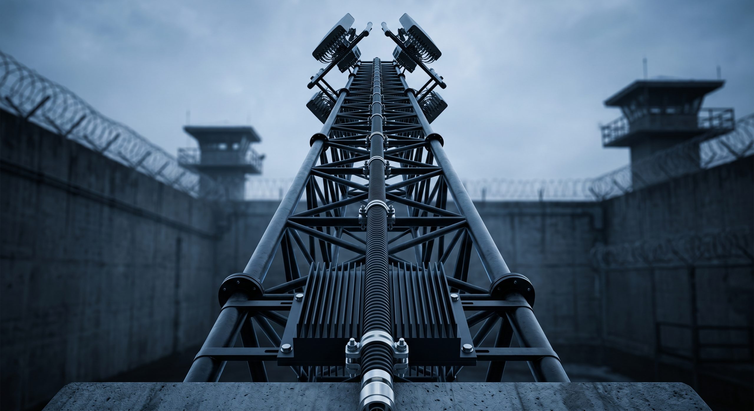
System integrators operating in the high-security physical defense sector constantly face a devastating engineering reality regarding radio frequency infrastructure. During the installation of prison jamming towers, technical crews routinely observe severe power degradation, noting that the amplifier’s output power rarely matches the radiated energy at the radome. This catastrophic discrepancy leads to compromised defensive perimeters, resulting in unmitigated drone flights and the continuous operation of illicit contraband communication devices within the facility. When high-power RF transmission lines suffer from long-distance insertion loss and mechanical failure caused by inferior connectors, the reflected energy returns down the line, permanently destroying output transistors through uncontrolled thermal runaway. To resolve this persistent hardware vulnerability, integrators must rely on the precise physical defense mechanisms engineered by CorelixRF. By understanding High-Power Jamming System Cabling Standards: How to Ensure 100W RF Energy Reaches the Antenna?, project managers can secure their defense perimeters with absolute certainty, utilizing laboratory-grade components to guarantee that maximum disruptive power successfully radiates from the tower apex.
Why Does RF Energy Vanish Before Reaching the Prison Tower Antenna?
The fundamental physics dictate… that coaxial transmission lines are not perfect lossless conductors, especially at higher spectrum allocations like the 5.7 to 5.9 GHz band. System integrators routinely mount the main power amplifier rack at the concrete base of a prison jamming tower and run 30 meters of vertical coaxial cable directly up to the sector antennas. They measure 100W of generated power at the amplifier output flange and falsely calculate that the antenna structure radiates this exact same magnitude. The physical reality involves massive dielectric dissipation and severe skin effect resistance, accumulating massive mathematical insertion loss over continuous long-distance vertical runs. For instance, attempting to utilize a standard commercial RG-214 braided cable at these microwave frequencies yields unacceptable attenuation parameters, physically transforming expensive RF power into waste heat trapped within the polymer jacket. When the radiated signal drops by a mathematical figure of 3dB, exactly half of the generated energy is physically lost, severely compromising the effective jamming radius. To maintain structural security and ensure the expected coverage footprint, engineers must abandon theoretical assumptions and analyze the raw transmission line parameters to calculate the true thermal losses occurring within the copper conduit.
| Cable Specification | 5.8 GHz Attenuation (dB/100m) | Power Delivered at 30m Run | Physical Core Structure |
| Standard RG-214 | > 85.0 dB | < 1W (Total Failure) | Stranded Copper / Braided |
| LMR-400 Flexible | 35.5 dB | 8.6W (Severe Loss) | Solid Copper Clad Aluminum |
| 1/2″ Corrugated | 12.4 dB | 42.4W (Moderate Loss) | Solid Corrugated Copper Tube |
| 7/8″ Corrugated | 7.2 dB | 60.8W (Standard B2B) | Solid Corrugated Copper Tube |
How Do Inferior Connectors Trigger Catastrophic Mechanical Failures?
Let’s examine the raw data… recovered from destructive field failure reports at maximum-security correctional facilities. Low-cost N-type or SMA connectors machined from inferior brass alloys introduce microscopic atmospheric air gaps and severe surface geometry irregularities into the signal path. When pushing continuous wave RF energy at maximum saturation, these microscopic mechanical imperfections cause massive impedance mismatches, physically sending high-voltage standing waves aggressively back down the transmission line. The resulting voltage standing wave ratio (VSWR) spike creates extreme voltage nodes localized precisely at the mating interface. This concentrated electrical stress ionizes the trapped atmospheric air, causing internal high-voltage arcing and immediate dielectric breakdown, physically melting the center pin and carbonizing the Teflon insulator. Once the mechanical integrity violently fails, the entire transmission chain suffers a permanent open circuit condition. The heavy reflected power then directly hits the final stage Gallium Nitride transistors. Without robust isolator protection, the solid-state transistors experience rapid thermal runaway and catastrophic structural fracturing, instantly turning a multi-thousand-dollar amplifier module into useless silicon slag within microseconds.
What Causes Thermal Expansion to Destroy Jamming System Interfaces?
Consider the physical reality… of outdoor high-altitude installations where ambient external temperatures fluctuate drastically between freezing midnight conditions and scorching afternoon solar loads. Dissimilar industrial metals utilized in the RF transmission path possess widely varying coefficients of thermal expansion. When 100W of continuous radio frequency power flows through the rigid system, the central copper inner conductor, the dielectric spacing material, and the outer metallic shielding heat up and expand at entirely different physical rates. Over a standard 24-hour operational duty cycle, this mechanical movement creates intense shear stress precisely at the internal crimp or solder joints. A poorly engineered interface will eventually suffer from cold-flow material creep, where the center conductor pin gradually pushes backward out of the female mating socket. This microscopic physical movement fundamentally alters the capacitive coupling of the joint, aggressively degrading the return loss metrics and increasing the forward insertion loss. Over several months of continuous thermal cycling, the internal connection becomes highly brittle, eventually fracturing the solder wick entirely or snapping the center pin, demanding heavy-duty materials engineered with closely matched thermal coefficients.
| Material Component | Thermal Expansion Coefficient (10−6/K) | Mechanical Stress Implication |
| PTFE (Teflon Dielectric) | 112.0 – 135.0 | Extremely high expansion, drives center pin out |
| Commercial Brass | 20.3 | High expansion, loosens mating threads over time |
| Beryllium Copper | 16.7 | Stable expansion, ideal for spring-loaded contacts |
| Invar (Alloy 36) | 1.2 | Minimal expansion, specialized high-stability filters |
How Can We Calculate the True Power Output at the Antenna Port?
Here is the engineering truth… regarding the precise mathematical link budget required for reliable structural perimeter defense. System architects must measure the exact attenuation laboratory figures provided by the physical cable manufacturer, carefully factoring in the specific microwave operating frequency and the maximum expected ambient temperature. Every single mechanical connector, inline lightning arrestor, and directional coupler inserted physically into the signal path introduces a calculable insertion loss penalty that cannot be ignored. If an installation team utilizes a heavy-duty 1/2-inch corrugated copper line with a specified loss of 12dB per 100 meters at 5.8 GHz, a standard 25-meter vertical run immediately subtracts exactly 3dB of power. Furthermore, flexible jumper cables physically interfacing the rigid main feedline to the final antenna port typically add an additional 0.5dB to 1.0dB of thermal loss. To successfully deliver a genuine 100W magnitude at the radiating radome, the internal amplifier output must be configured significantly higher, or the physical cable routing must be drastically shortened. Employing a calibrated Vector Network Analyzer to meticulously sweep the entire completed cable assembly remains the only mathematically acceptable procedure.
Why Do Passive Intermodulation Issues Degrade Signal Quality?
Let’s examine the raw data… surrounding the frequently ignored mechanical phenomenon of passive intermodulation (PIM) within high-power defense transmission systems. When multiple high-power RF carriers transmit simultaneously through a complex prison jamming tower, any non-linear metallic junction physically located in the cable path acts as a parasitic frequency mixer. Ferromagnetic plating materials, heavily oxidized metal contacts, and microscopic metal shavings carelessly left behind during improper cable termination generate severe spurious emission products. These unwanted generated frequencies fall right back into the sensitive receive bands or critical internal communication channels, causing massive self-interference. An incorrectly torqued RF connector can immediately introduce a PIM spike of -90 dBc, entirely nullifying the pristine spectral purity originally generated by the source amplifier transmitter. To guarantee the required -150 dBc or better PIM rating, installation technicians must mandate specialized preparation tools, aggressively reject any nickel-plated components within the RF path, and meticulously clean all metal mating surfaces with 99% isopropyl alcohol to ensure zero particulate contamination.
| Connector Condition | Expected PIM Value (dBc) | Operational Impact on Jamming System |
| Precision Silver-Plated, Torqued | -160 to -165 | Pristine spectral purity, zero interference |
| Standard Brass, Hand Tightened | -110 to -120 | Moderate noise floor elevation |
| Nickel-Plated Components Present | -80 to -90 | Severe self-interference, blocked channels |
| Oxidized Contacts / Metal Shavings | -60 to -70 | Complete communication blackout risk |
What Is the Impact of Moisture Ingress on Microwave Transmission Lines?
The fundamental physics dictate… that atmospheric water vapor acts as a highly effective physical absorber of concentrated microwave energy. In heavily exposed outdoor prison tower deployments, wind-driven torrential rain, extreme coastal humidity, and continuous diurnal temperature swings inevitably lead to severe internal condensation if the RF joints are not perfectly hermetically sealed. When liquid moisture physically penetrates the outer polyethylene jacket of a coaxial cable or successfully breaches the rubber O-ring of an improperly tightened connector, it drastically alters the dielectric constant of the internal insulator. This physical infiltration immediately shifts the characteristic impedance violently away from 50 ohms, causing massive forward signal reflection. More destructively, the water molecules violently vibrate and oscillate in the direct presence of 100W of RF energy, absorbing the generated power and physically converting it into localized expanding steam. This extreme localized heating dramatically accelerates the chemical oxidation of the internal copper shielding, permanently creating a non-reversible degradation of the transmission line that demands full replacement.
How Does the CRF-PA-5700M5900M-100W Defend Against Mismatched Loads?
Here is the engineering truth… regarding critical equipment survivability when external field cabling inevitably degrades under harsh environmental conditions. The CorelixRF engineering manufacturing facility specifically designed the CRF-PA-5700M5900M-100W module to easily withstand the most violent mechanical failures present in real-world B2B defense deployments. Operating strictly within the 5700 MHz to 5900 MHz physical spectrum, this heavy-duty module incorporates a massive, high-isolation drop-in ferrite circulator mounted directly at its final output stage. When a severely crushed connector or physically water-logged transmission cable causes 100% of the forward power to reflect backward, the magnetic circulator automatically routes this highly destructive energy directly into a bolted high-power beryllium oxide termination resistor. Instead of violently shattering the sensitive output matching network of the GaN transistors, the reflected power is safely and silently dissipated as thermal heat through our heavy oversized, CNC-machined aluminum metallic heatsink. This ruggedized physical architecture ensures that the hardware remains fully operational even when the external antenna system is entirely mechanically destroyed.
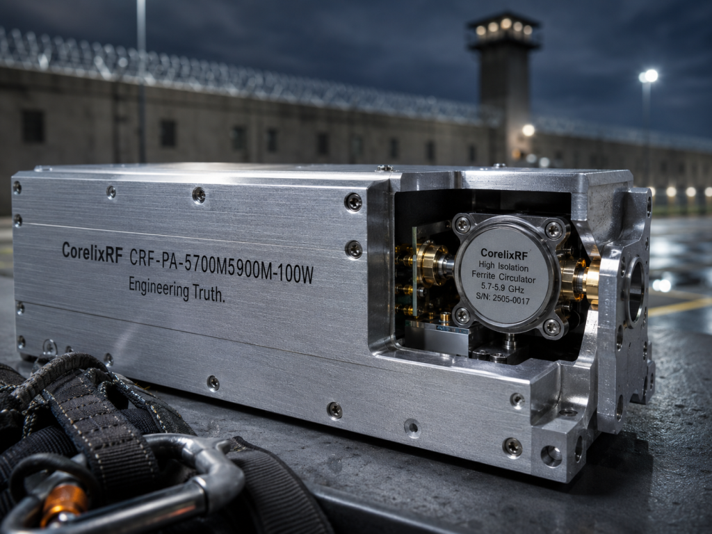
| Module Protection Feature | Technical Specification | Direct Defense Mechanism |
| Output Stage Circulator | 25dB Minimum Isolation | Redirects 100% reflected power away from GaN |
| Beryllium Oxide Resistor | 150W Continuous Rating | Absorbs returning VSWR energy as thermal heat |
| CNC Aluminum Heatsink | 0.4 °C/W Thermal Resistance | Rapidly dissipates heat from the termination resistor |
| Over-Current Logic Board | 10 Microsecond Response | Shuts down DC bias during severe transient arcs |
Which RF Cable Types Survive Continuous Duty Cycles in Prison Environments?
Consider the physical reality… of selecting the absolutely correct transmission medium for continuous, unrelenting 24/7 high-power jamming operations. Flexible, braided commercial cables similar to LMR-400 may offer significantly easier routing bends during tight installation procedures, but their internal dual foil and braided structure completely struggles to handle the immense thermal load of continuous 100W RF power at high microwave frequency bands. The constant thermal heating and cooling cycling causes the internal aluminum foil to micro-crack and the copper braid to mechanically loosen, generating massive internal PIM and destructive micro-arcing. For completely uncompromised continuous energy transfer, heavy rigid or semi-rigid corrugated solid copper cables, physically representing 1/2-inch or 7/8-inch outer diameters, represent the strictly mandated standard. The solid continuous tubular outer conductor provides incredibly superior RF shielding, absolutely zero-radiation physical leakage, and unmatched physical thermal conductivity to aggressively sink waste heat away from the dielectric core.
How Do We Verify Connection Integrity Without Dismantling the Tower?
Let’s examine the raw data… collection methodologies utilized daily by highly trained tier-one defense system integrators. Blindly trusting visual physical inspections or basic digital multimeter DC continuity checks is a guaranteed mathematical recipe for catastrophic operational system failure. Professional field engineers must heavily utilize Time Domain Reflectometry (TDR) and strict Distance-to-Fault (DTF) microwave measurements using a calibrated, portable Vector Network Analyzer (VNA). By physically injecting a continuously swept frequency signal directly into the base of the transmission line, the heavy-duty VNA precisely records the exact magnitude and phase shift of the reflected returning signals. Complex internal mathematical Fourier transforms instantly convert this raw frequency-domain data into a highly precise spatial physical map of the entire cable run. This powerful diagnostic capability allows mechanical technicians to accurately pinpoint the exact physical location of a crushed cable jacket, a water-infiltrated top connector, or a loosely torqued mating interface down to the exact millimeter.
| Diagnostic Tool | Measurement Capability | Operational Value for System Integrator |
| Digital Multimeter | DC Continuity / Short Circuit | Low. Cannot detect RF impedance mismatch. |
| Power Meter | Forward / Reflected Power | Medium. Identifies a problem exists, not location. |
| Vector Network Analyzer | VSWR / Return Loss Sweep | High. Verifies exact electrical match across band. |
| Distance-to-Fault (DTF) | TDR Spatial Mapping | Critical. Pinpoints precise physical millimeter of failure. |
What Are the Long-Term ROI Metrics of Strict Engineering Compliance?
Here is the engineering truth… deeply regarding the financial heavy economics of industrial radio frequency infrastructure. Corporate procurement managers frequently attempt to aggressively reduce immediate capital expenditure by carelessly selecting low-tier commercial-grade cables and unbranded mechanical connectors, falsely treating them as low-priority passive bulk components. This mathematically flawed calculus completely ignores the massive total cost of ownership facing the installation company. A single catastrophic mechanical failure of a cheap brass connector not only inevitably results in the fiery destruction of the high-power transmitter module but also strictly mandates the incredibly expensive emergency dispatch of specialized high-angle climbing rescue teams to physically scale the correctional facility tower. The immediate hazardous labor costs alone massively exceed the initial price difference of correctly specifying heavy aerospace-grade components from day one. By standardizing firmly on rigid CorelixRF technical specifications and adhering strictly to tight microwave cabling tolerances, defense system integrators logically guarantee decades of continuous, fault-free thermal operation.
In final analysis, the laws of physics heavily penalize systemic compromises in radio frequency infrastructure. Maintaining pristine 50-ohm characteristic impedance, aggressively combating physical thermal expansion, and effectively neutralizing heavy VSWR reflections are non-negotiable mandates for robust perimeter defense systems. Utilizing properly matched corrugated copper transmission lines and strictly torqued beryllium copper connectors prevents the catastrophic destruction of expensive internal amplifier modules. The CorelixRF engineering methodology strictly focuses on physical hardware resilience, proven by the ruggedized circulator protection built directly into our amplifier architecture. We urge all professional system integrators, R&D directors, and military contractors to base their infrastructure decisions strictly on physical laboratory realities rather than theoretical marketing claims. Contact the CorelixRF engineering manufacturing team today to request the highly detailed technical Data Sheet for the CRF-PA-5700M5900M-100W and secure your operational perimeters with unmatched physical reliability.
Frequently Asked Questions (FAQ)
Q1: Why does my power meter show a 30% drop in RF output after 10 minutes of continuous operation?
This specific mathematical drop is entirely caused by uncontrolled thermal expansion within a severely degraded coaxial connector or a heavily overheating final transistor stage. As the internal physical materials rapidly heat, the impedance mismatch expands, drastically increasing your VSWR and triggering the amplifier’s internal protection circuits to throttle forward current.
Q2: Can I use standard LMR-400 cable for the CRF-PA-5700M5900M-100W if the tower is under 15 meters?
While mechanically possible, it is strongly advised against for continuous B2B duty cycles. The internal braided shield of LMR-400 physically struggles to effectively dissipate the extreme thermal load generated by 100W continuous wave energy at 5.8 GHz, inevitably leading to premature dielectric melting.
Q3: How exactly does the built-in drop-in circulator protect the internal amplifier module?
The magnetic ferrite circulator acts as a strict physical one-way valve for microwave energy. If an external cable breaks, the massive returning reflected power is magnetically steered forcefully into an internal heavy-duty beryllium oxide dummy load, completely isolating the fragile GaN transistors from the destructive high-voltage spikes.
Q4: What is the maximum acceptable VSWR reading for a newly installed prison jamming tower?
For highly reliable continuous military-grade operation, the maximum acceptable system VSWR measured directly at the base input of the main transmission line must remain strictly below 1.5:1 (a return loss greater than 14 dB) across the entire operational sweeping frequency band.
Q5: Why is 99% isopropyl alcohol specifically mandated for cleaning RF connectors before mating?
Standard industrial cleaners permanently leave behind heavy microscopic chemical films that actively alter the critical capacitive coupling of the RF joint. Pure 99% isopropyl alcohol heavily evaporates completely without any physical residue, guaranteeing highly pristine metal-to-metal contact and actively preventing severe passive intermodulation (PIM) interference.
Authorized RF engineering and compliance review
For regulated RF systems, this page should be used as an engineering and compliance review path, not as a public deployment checklist. CorelixRF starts with authorization status, operating region, frequency plan, output limit, antenna interface, safety controls, thermal limits and acceptance documents.
- RFQ checklist – send the data buyers usually forget, including band, power, duty cycle, interface and test standard
- delivery documentation – check what documents can support incoming inspection, FAT review and long-term maintenance
- quality and certification review – review the quality and compliance evidence before the project moves into procurement
- RF front-end platform – compare the RF chain as a system instead of selecting one isolated module
- RF configurator – turn frequency, power, thermal and interface requirements into a first configuration brief
- case studies – review similar engineering paths before sending an RFQ
- engineering contact – send the application notes, block diagram or target specification to engineering sales
This keeps the discussion inside lawful, authorized RF programs while still giving procurement teams a clear way to request amplifier, antenna, SDR source, documentation and factory review.