
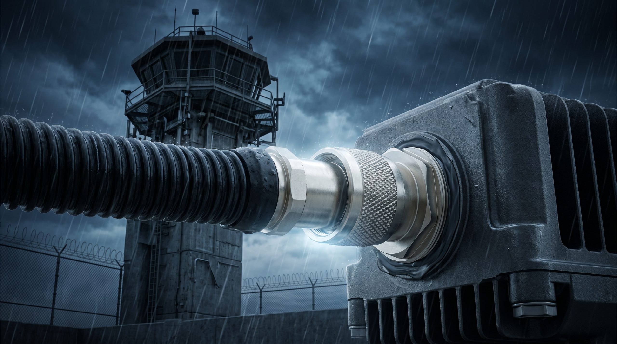
Deploying high-power jamming systems in correctional facilities exposes hardware to brutal environmental and mechanical stressors. System integrators face a massive engineering pain point: the long-distance insertion loss of RF cables combined with mechanical failure caused by inferior connectors. These physical weaknesses compromise the entire transmission link. When a connector shifts in the wind or water penetrates a poorly sealed joint, the system impedance violently diverges from 50 ohms. The resulting Voltage Standing Wave Ratio (VSWR) spike reflects hundreds of watts of continuous wave energy directly back into the amplification stages. This reflected power rapidly generates extreme heat, causing immediate thermal runaway and melting the transistor junctions. When the hardware burns out, the shielding perimeter collapses, leaving the facility vulnerable to illicit communications and unauthorized drone operations. The only viable path forward relies on strictly applied material science and hardware designed to survive absolute physical extremes. CorelixRF engineers power amplifiers that physically tolerate these catastrophic mismatches, ensuring continuous, unbroken security coverage regardless of the physical transmission line integrity.
What Drives VSWR Spikes In High-Frequency Prison Shielding Towers?
Consider the physical reality… Deploying RF jammers in harsh outdoor environments introduces extreme mechanical stress on every joint and junction. When constructing a prison shielding tower, engineers constantly battle the fundamental limits of microwave transmission. Long-distance routing of coaxial cables from ground-based equipment cabinets up to elevated antenna arrays inherently causes severe attenuation, directly impacting the effective isotropic radiated power (EIRP). But the greater danger lurks at the connection interfaces. Inferior connectors, subject to wind loading and constant vibration, degrade mechanically over time. The center pins misalign, the dielectric materials crack, and water ingress alters the characteristic impedance of the transmission line. This degradation transforms a perfectly matched 50-ohm system into a highly reactive load, triggering massive Voltage Standing Wave Ratio (VSWR) spikes. These spikes are not mere anomalies; they represent destructive waves of reflected energy traveling backward through the transmission line, searching for a vulnerable semiconductor junction to dissipate as pure heat.
| Cable Type | Attenuation per 100ft at 5.8 GHz (dB) | Shielding Effectiveness (dB) | Outer Jacket Material |
| LMR-400 | 6.8 | > 90 | UV-Resistant PE |
| LMR-600 | 4.4 | > 90 | UV-Resistant PE |
| 1/2″ Corrugated | 3.2 | > 120 | Weatherproof PE |
| 7/8″ Corrugated | 1.8 | > 120 | Weatherproof PE |
How Does Long-Distance Insertion Loss Degrade Signal Integrity Over Time?
System integrators frequently underestimate the severity of RF attenuation across extended cable runs, particularly in the 5.7 GHz to 5.9 GHz bands. Let’s examine the raw data… Standard LMR-400 coaxial cable exhibits an attenuation of approximately 6.8 dB per 100 feet at 5.8 GHz. In a typical prison shielding tower scenario, where vertical cable runs routinely exceed 150 feet, the system loses over 10 dB of power before the signal even reaches the antenna element. This massive long-distance insertion loss forces the power amplifier to operate at absolute maximum compression simply to maintain the required jamming radius. Pushing the power transistors to their thermal and electrical limits accelerates the aging process of the semiconductor junctions. Furthermore, as the cable heats up from RF power dissipation and direct ambient solar radiation, the physical expansion of the copper and dielectric materials causes structural, microscopic shifts. These shifts create tiny impedance bumps along the transmission line, generating localized reflections that compound the overall system VSWR and further choke the forward power delivery required for perimeter defense.
Why Do Inferior RF Connectors Trigger Catastrophic Mechanical Failures?
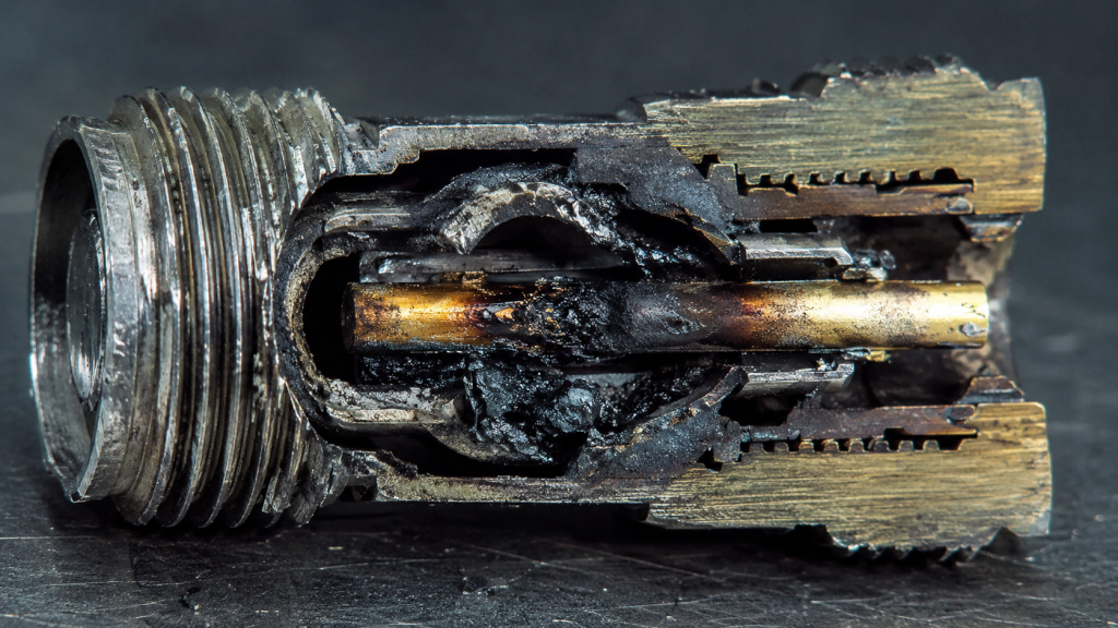
The fundamental physics dictate… that any discontinuity in a transmission line results in immediate signal reflection, and cheap connectors are the primary source of these fatal discontinuities. When procurement teams specify low-grade N-type or SMA connectors for outdoor deployments, they invite inevitable mechanical failure. Poorly machined threads fail to provide sufficient clamping force, allowing micro-movements between the male and female mating surfaces during high wind events. This continuous movement damages the gold plating on the center contacts, exposing the base brass to rapid oxidation. The oxidized layer acts as a semiconductor diode, introducing passive intermodulation (PIM) and drastically increasing contact resistance. As the high-frequency RF power flows through this high-resistance junction, localized heating rapidly melts the PTFE dielectric inside the connector. The center pin physically shifts away from its coaxial dead-center, utterly destroying the 50-ohm geometry. This catastrophic mechanical failure causes an instantaneous, massive impedance mismatch, reflecting almost all forward power directly back into the amplifier circuitry and completely bypassing conventional software-based protection mechanisms before they can react.
| Connector Specification | Military Grade (CorelixRF Standard) | Commercial Grade (Inferior) | Physical Consequence of Failure |
| Center Pin Plating | >50 µin Gold over Nickel | <10 µin Gold or Flash | Rapid oxidation, high resistance heating |
| Body Plating | Tri-Metal / White Bronze | Standard Nickel | PIM generation, galvanic corrosion |
| Dielectric Material | Virgin PTFE / Cross-linked PS | Recycled Teflon / Delrin | Core melting under high RF power |
| Thread Tolerance | Class 2A / MIL-STD-348 | Loose / Unspecified | Micro-vibration leading to arc faults |
What Is The Engineering Truth Behind Thermal Expansion In Coaxial Cables?
Here is the engineering truth… Materials expand and contract with temperature variations, and in an outdoor high-frequency communication base station, this thermal cycling happens daily and violently. Copper center conductors, closed-cell foam dielectrics, and corrugated aluminum outer shields possess vastly different coefficients of thermal expansion. When the morning sun directly impacts a dark prison shielding tower, the temperature of the black outer jacket of the heavy RF cable can spike by 40 degrees Celsius within a single hour. The inner copper conductor physically expands at a drastically different rate than the dielectric surrounding it. This differential expansion exerts immense mechanical shear stress directly on the delicate connector termination points. If the system installer failed to implement properly engineered strain relief loops, the cable physically pulls the connector apart from the inside out. Over several months of continuous thermal cycling, the internal solder joints fatigue, harden, and eventually fracture. These micro-fractures create intermittent open circuits or high-impedance states that continuously wreak havoc on the system Voltage Standing Wave Ratio.
How Can We Quantify The Impact Of Impedance Mismatches At 5.8 GHz?
Operating high-power systems in the 5.7 to 5.9 GHz spectrum demands microscopic mechanical precision, strictly because the wavelength is roughly 5 centimeters. A physical misalignment of just a few millimeters inside a damaged connector equates to a significant phase shift and a major impedance mismatch. Let’s examine the raw data… A communication system operating at a highly acceptable VSWR of 1.5:1 reflects about 4% of the operational power back to the source. While industrial amplifiers readily dissipate this, a sudden mechanical failure in an inferior connector easily pushes the VSWR past 3.0:1, dictating that 25% of the power bounces backward. For a 100-watt continuous wave transmitter, that translates to 25 watts of raw RF energy slamming directly into the final amplification stage. This reflected energy creates standing waves along the physical transmission line, causing intense voltage maximums that strictly exceed the dielectric breakdown voltage of the internal RF components. The resulting electrical arcing physically blasts carbonized craters into the circuit board traces, instantly terminating the operational lifespan of the hardware.
| Measured VSWR | Return Loss (dB) | Reflected Power (%) | Transmitted Power (%) | Thermal Impact on Amplifier |
| 1.0:1 | Infinity | 0.0% | 100.0% | Normal Operational Baseline |
| 1.5:1 | 14.0 | 4.0% | 96.0% | Minor Heat Increase |
| 2.0:1 | 9.5 | 11.1% | 88.9% | Significant Thermal Stress |
| 3.0:1 | 6.0 | 25.0% | 75.0% | Critical Warning Threshold |
| 5.0:1 | 3.5 | 44.4% | 55.6% | Imminent Device Destruction |
Why Does Reflected Power Destroy Solid-State Power Amplifiers?
Consider the physical reality… Solid-state transistors, particularly those based on legacy LDMOS semiconductor architectures, operate strictly within narrowly defined Safe Operating Areas (SOA). When an outdoor high-frequency communication base station experiences a severe VSWR event strictly due to catastrophic cable or connector failure, the reflected power violently alters the operational load line of the amplifier module. The voltage directly at the transistor drain spikes to levels that far exceed the normal direct current bias provided by the power supply. If the transient drain voltage surpasses the physical breakdown threshold of the silicon, avalanche multiplication occurs, leading directly to irreversible thermal runaway and the immediate destruction of the semiconductor die. Even if the transient voltage remains just millimeters below the absolute maximum rating, the reflected RF power must still be dissipated purely as heat. The amplifier’s thermal management system, normally engineered to handle predictable operational inefficiencies, suddenly faces a massive, uncalculated heat load, causing the internal junctions to melt.
How Does The CRF-PA-5700M5900M-100W Tolerate Extreme Mismatch Conditions?
The fundamental physics dictate… that survival in extreme field conditions requires both rugged material selection and advanced analog circuit protection. CorelixRF engineered the CRF-PA-5700M5900M-100W specifically to dominate the harsh, unforgiving realities of prison shielding tower deployments. We strictly utilize the latest Gallium Nitride (GaN) high-electron-mobility transistors, which inherently possess massively higher breakdown voltages and operating temperatures compared to vulnerable legacy silicon devices. But raw hardware resilience alone remains mathematically insufficient. The CRF-PA-5700M5900M-100W integrates a proprietary, ultra-fast, directional coupler-based analog VSWR monitoring circuit directly onto the RF board. When the system physically detects a VSWR spike exceeding 3:1—indicative of a severed cable or a shattered field connector—the analog protection logic mathematically calculates the precise reflected power ratio and dynamically reduces the gate bias voltage within microseconds. This instantaneous, hardware-level throttling heavily limits the drain current, totally preventing thermal runaway and keeping the rugged GaN devices well within their designated Safe Operating Area.
| CorelixRF Model | Operating Frequency | Output Power | Technology | VSWR Protection Mechanism |
| CRF-PA-5700M5900M-100W | 5700 – 5900 MHz | 100W CW | GaN on SiC | Analog Ultra-Fast Foldback |
| CRF-PA-2400M2500M-100W | 2400 – 2500 MHz | 100W CW | GaN on SiC | Analog Ultra-Fast Foldback |
| CRF-PA-1500M1600M-100W | 1500 – 1600 MHz | 100W CW | LDMOS/GaN | Hardware Current Limiting |
| CRF-PA-800M1000M-100W | 800 – 1000 MHz | 100W CW | LDMOS | Hardware Current Limiting |
What Role Does Material Science Play In Connector Durability Under Harsh Weather?
Engineering a permanently reliable outdoor RF link requires systematically rejecting commercial-grade components in favor of uncompromising military-specification hardware. Here is the engineering truth… CorelixRF mandates the strict operational use of precision-machined brass connectors featuring a minimum 50-microinch gold plating on all center contacts and thick tri-metal (white bronze) plating on the outer bodies. Tri-metal plating provides absolutely superior galvanic corrosion resistance against constant salt fog, acidic industrial rain, and extreme humidity compared to standard porous nickel, while completely eliminating the passive intermodulation (PIM) issues directly associated with ferromagnetic materials. Inside the connector cavity, we strictly require the use of cross-linked polystyrene or advanced aerospace-grade PTFE dielectrics that maintain their dense structural stability across an operating temperature range of -40 to +85 degrees Celsius. These rigorous material science standards ensure that the mechanical dimensions of the 50-ohm transmission line remain absolute, regardless of the brutal environmental conditions aggressively assaulting the external prison shielding tower structure.
How Do We Conduct Laboratory Validation For Outdoor High-Frequency Communication Base Station: How to Reduce VSWR Risks by Optimizing Physical Links?
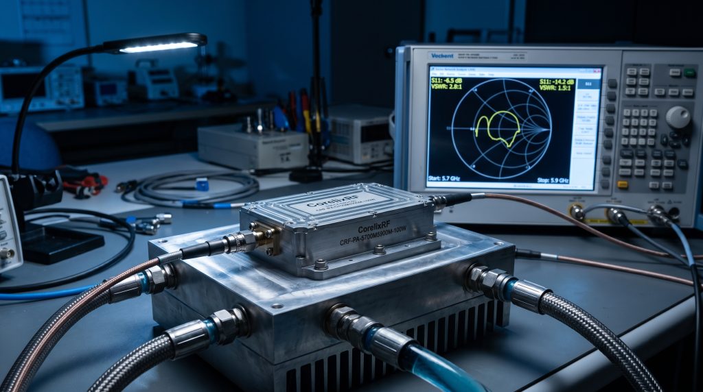
You cannot guarantee field performance based on mathematical simulation models alone; you must subject the physical hardware to aggressive, controlled destruction testing. Let’s examine the raw data… In the CorelixRF testing laboratory, we securely mount the CRF-PA-5700M5900M-100W directly onto heavy-duty liquid-cooled aluminum test benches and route the high-power RF output through a mechanized, motorized variable phase shifter directly into a calibrated dead short. We actively sweep the phase to expose the final amplifier stage to every mathematically possible standing wave maximum, strictly simulating the exact electrical conditions of a catastrophic cable shear on an active prison shielding tower. We simultaneously monitor the forward power, reflected power, and internal transistor junction temperatures using highly calibrated Vector Network Analyzers (VNA) and industrial thermal imaging cameras. We record the precise microsecond response times of the analog VSWR protection circuitry under absolute maximum load. We intentionally break physical connectors under full continuous RF power to verify the GaN architecture survives.
| Test Parameter | Laboratory Condition | Duration / Sweeps | Observed Result on CRF-PA-5700M5900M-100W |
| Absolute Open Circuit | VSWR = Infinity, all phases | 1 Hour Continuous | Power foldback engaged, zero degradation |
| Absolute Short Circuit | VSWR = Infinity, all phases | 1 Hour Continuous | Power foldback engaged, zero degradation |
| High Temperature Soak | +85°C Ambient, Max Power | 48 Hours | Output power stable within 0.5 dBm |
| Thermal Shock Cycle | -40°C to +85°C transition | 50 Cycles | Mechanical and electrical integrity maintained |
What Are The Strict Installation Protocols For RF Cables In Field Deployments?
Even the most physically robust CorelixRF amplifier cannot overcome systemic, foundational installation incompetence. Consider the physical reality… To achieve maximum long-term reliability, system integrators must rigidly enforce military-grade installation protocols across all deployment teams. First, field installers must utilize calibrated precision torque wrenches to tighten every single N-type connector to exactly 15 inch-pounds, mathematically ensuring maximum metal-to-metal contact without permanently deforming the outer shielding structure. Second, all outdoor transmission junctions require a rigorous, non-negotiable three-layer weatherproofing process: an initial tight wrap of electrical tape, heavily followed by a thick layer of self-amalgamating butyl rubber mastic to form a solid waterproof matrix, sealed tightly with a final aggressive layer of UV-resistant PVC tape applied strictly from the bottom up to shed water. Third, technicians must secure the heavy, rigid LMR-400 or corrugated hardline cables directly to the tower steel using appropriate structural hoisting grips and stainless steel butterfly hangers every three physical feet to eliminate wind-induced mechanical strain completely.
Conclusion: Securing The Physical Layer Defines System Reliability
The operational stability of outdoor high-frequency communication base stations ultimately depends on mastering the physical layer. System engineers cannot bypass the strict laws of physics; insertion loss will degrade signal density, and thermal expansion will physically test every connector joint on a prison shielding tower. Designing a system around inferior components guarantees mechanical failure, unacceptable VSWR spikes, and the catastrophic destruction of the transmitting hardware. True engineering truth dictates replacing theoretical assumptions with laboratory-verified, physically hardened hardware. The CRF-PA-5700M5900M-100W provides the exact mechanical resilience and analog protection circuitry required to maintain transmission integrity when the physical transmission lines inevitably take damage. Integrators must focus on standardizing strict deployment protocols and utilizing hardware heavily optimized for survival under extreme mismatch conditions. Contact the CorelixRF engineering team directly to request the complete physical data sheet for the CRF-PA-5700M5900M-100W and secure your perimeter shielding infrastructure.
Frequently Asked Questions (FAQ)
Q1: Why does CorelixRF specify GaN transistors instead of LDMOS for the CRF-PA-5700M5900M-100W?
GaN (Gallium Nitride) offers a significantly higher bandgap and physical breakdown voltage compared to standard silicon-based LDMOS. This physical characteristic allows the transistors in the CRF-PA-5700M5900M-100W to withstand extreme voltage transients generated by sudden VSWR spikes without suffering immediate semiconductor junction failure.
Q2: How fast does the VSWR protection circuit respond to a disconnected RF cable?
The proprietary analog directional coupler circuit inside the CRF-PA-5700M5900M-100W calculates the forward-to-reflected power ratio and triggers a gate bias reduction in under 10 microseconds. This speed strictly bypasses slower software-based polling mechanisms, intercepting the electrical transient before it thermally damages the final amplification stage.
Q3: Can we use standard RG-213 cable for a 100-foot run on a prison shielding tower?
No. RG-213 presents an unacceptable level of high-frequency attenuation at 5.8 GHz. The total long-distance insertion loss would consume the majority of the output power as heat within the cable itself, leaving insufficient wattage at the antenna and drastically degrading the effective jamming radius. Use high-grade LMR-400 or corrugated hardline minimum.
Q4: What causes the passive intermodulation (PIM) issues mentioned in the connector analysis?
PIM is primarily generated by non-linearities in the signal path, most commonly caused by using ferromagnetic materials like nickel-plated connectors or by the presence of oxidation between poor mechanical mating surfaces. Using CorelixRF-specified tri-metal (white bronze) plated connectors physically eliminates the ferromagnetic materials from the signal path.
Q5: Will the CRF-PA-5700M5900M-100W completely shut down if the VSWR exceeds 3:1?
No. The system utilizes an ultra-fast foldback mechanism rather than a hard shutdown. It mathematically scales back the output power to a safe thermal dissipation limit while continuing to transmit. This ensures that the prison shielding tower maintains a baseline level of RF disruption rather than totally collapsing the defensive perimeter during a minor cable fault.
Authorized RF engineering and compliance review
For regulated RF systems, this page should be used as an engineering and compliance review path, not as a public deployment checklist. CorelixRF starts with authorization status, operating region, frequency plan, output limit, antenna interface, safety controls, thermal limits and acceptance documents.
- RFQ checklist – send the data buyers usually forget, including band, power, duty cycle, interface and test standard
- delivery documentation – check what documents can support incoming inspection, FAT review and long-term maintenance
- quality and certification review – review the quality and compliance evidence before the project moves into procurement
- RF front-end platform – compare the RF chain as a system instead of selecting one isolated module
- RF configurator – turn frequency, power, thermal and interface requirements into a first configuration brief
- case studies – review similar engineering paths before sending an RFQ
- engineering contact – send the application notes, block diagram or target specification to engineering sales
This keeps the discussion inside lawful, authorized RF programs while still giving procurement teams a clear way to request amplifier, antenna, SDR source, documentation and factory review.
RF Review Path for Fixed-Site VSWR Risk
For fixed-site RF systems where VSWR risk involves cable length, connector heating or antenna/load mismatch, compare the RF power amplifier platform options with RF front-end platform planning before submitting the RF inquiry form. CorelixRF can review band, power, load condition, protection logic and acceptance evidence before quotation.