
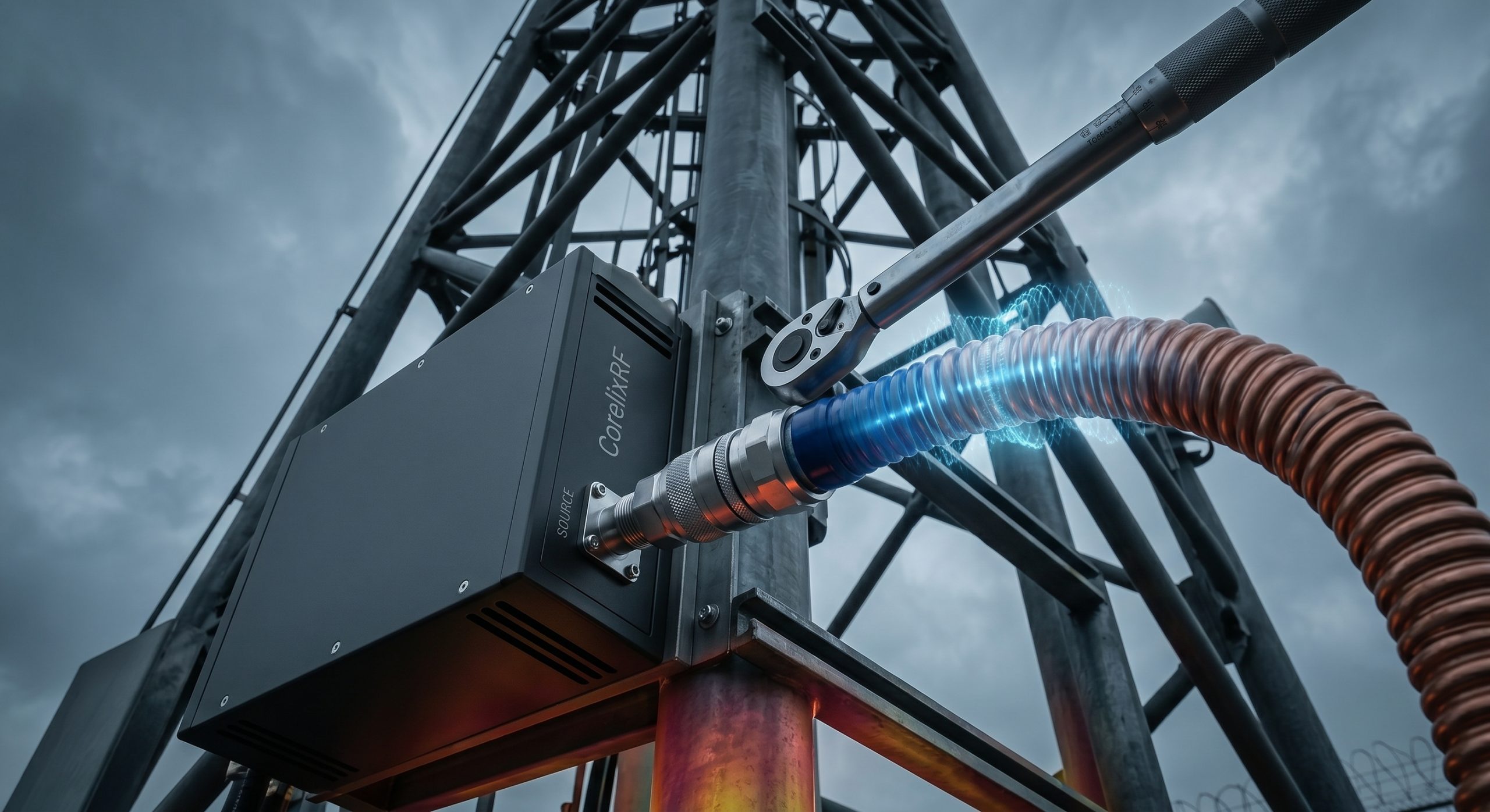
System integration for high-frequency defense infrastructure is a continuous battle against physical limitations. When deploying RF modules in elevated environments like a prison jamming tower, engineers face a highly destructive reality: you generate 100W of raw output at the base station, but only a fraction of that energy actually radiates from the antenna. Long-distance insertion loss and catastrophic mechanical failures caused by inferior connectors continuously degrade the signal structure before it ever leaves the vertical structural column.
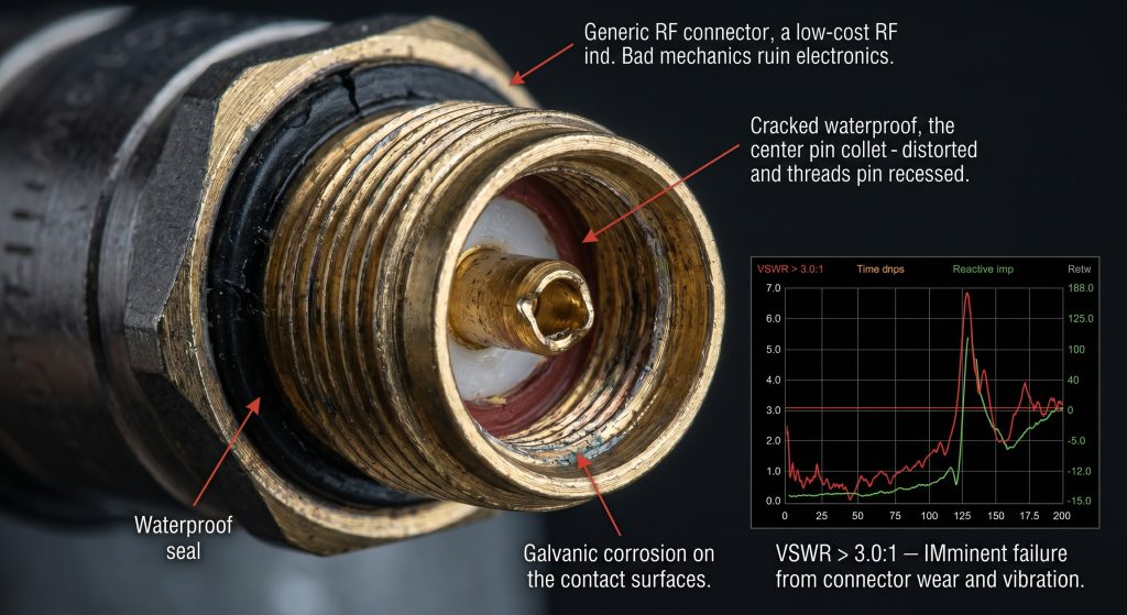
This severe impedance mismatch and subsequent thermal expansion completely destroy the system’s Voltage Standing Wave Ratio (VSWR). Reflected power travels backward down the transmission line, heavily stressing the final stage power transistors. When a secure facility’s perimeter defense relies on continuous wave jamming in the 5.7 to 5.9 GHz band, this rapid signal attenuation leads to immediate operational collapse. The defensive boundary fails, leaving the airspace wide open to unauthorized drone incursions.
CorelixRF firmly rejects theoretical marketing estimations in favor of hardened physical realities. We engineer high-power microwave modules to survive the extreme mechanical and electrical stresses of vertical tower deployments. The CRF-PA-5700M5900M-100W stands as the definitive hardware solution, providing the extreme physical tolerance required to overcome high-altitude cabling physics and deliver uninterrupted RF energy directly to the radiating element.
Why Does Long-Distance Insertion Loss Destroy System Budgets?
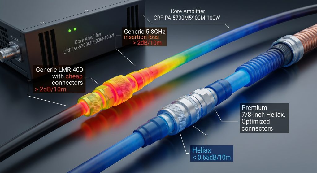
Let’s examine the raw data… When system integrators calculate their link budgets for high-frequency applications, they frequently ignore the severe attenuation inherent in long-distance vertical transmission lines. A prison jamming tower demands antennas mounted thirty to fifty meters above the equipment shelter. At frequencies between 5700 MHz and 5900 MHz, the strict laws of physics heavily penalize every single meter of coaxial cable. Using standard LMR-400 cable yields an insertion loss exceeding 2 dB per ten meters, meaning a 100W signal from the amplifier degrades to a fraction of its original power before it ever reaches the radiating element. Engineers must transition to rigid or semi-rigid corrugated copper cables, such as 7/8-inch EIA Heliax, to mitigate this severe signal degradation. The dielectric losses and skin effect resistance inside the transmission line literally convert expensive RF energy into useless thermal dissipation, actively starving the antenna of the required amplitude to maintain a secure defensive perimeter against unauthorized drone incursions.
| Coaxial Cable Type | Attenuation per 10m at 5.8 GHz | Output from 100W Source | Thermal Load Rating |
| Standard RG-214 | 4.80 dB | 33.1 Watts | Failure Imminent |
| Braided LMR-400 | 2.10 dB | 61.6 Watts | Marginal Stability |
| 1/2″ Corrugated | 1.15 dB | 76.7 Watts | Professional Standard |
| 7/8″ Corrugated | 0.65 dB | 86.1 Watts | Maximum Efficiency |
What Causes Mechanical Failure in RF Connectors on Towers?
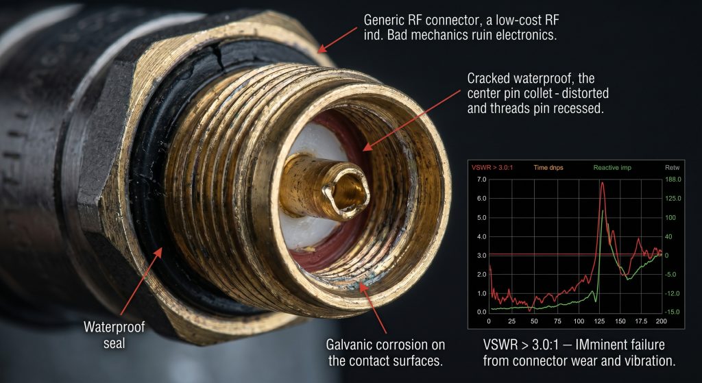
The fundamental physics dictate… that continuous mechanical stress directly translates into permanent electrical impedance variations over time. In a prison jamming tower deployment, the heavy corrugated coaxial cables exert immense downward gravitational force on the connector interfaces. Inferior connectors manufactured from cheap brass alloys suffer from severe thread stripping and center pin deformation under this continuous mechanical load. Wind shear against the steel tower structure creates high-frequency micro-vibrations, gradually loosening standard connectors that lack proper torque specifications and internal anti-rotation locking mechanisms. Once the mechanical bond degrades, the precise 50-ohm geometry of the connector interface is permanently destroyed. This microscopic physical separation introduces a massive capacitive or inductive reactance spike, immediately resulting in dangerous impedance mismatch. Moisture ingress instantly follows the mechanical breach, rapidly accelerating galvanic corrosion between the dissimilar metals. CorelixRF completely rejects the use of standard commercial components, mandating severe-duty military-grade interfaces that maintain absolute dimensional stability under continuous structural tension and harsh atmospheric exposure.
How Does Impedance Mismatch Trigger Catastrophic GaN Failure?
Here is the engineering truth… Solid-state Gallium Nitride (GaN) transistors possess immense power density but demand strict load matching to survive continuous wave operation at maximum output. When long-distance insertion loss and mechanical connector failures compound, the resulting impedance mismatch creates a severe Voltage Standing Wave Ratio (VSWR) anomaly. The 100W forward power hits the compromised connector or degraded cable geometry and reflects straight back down the transmission line into the final amplifier stage. This reflected energy generates destructive standing waves that effectively double the peak voltage across the GaN transistor drain, exceeding the absolute maximum dielectric breakdown threshold of the semiconductor material. The excessive heat localized at the semiconductor junction simply cannot be dissipated through the baseplate heat sink fast enough, leading directly to thermal runaway and permanent catastrophic device failure. CorelixRF engineers tightly integrate robust internal isolators to absorb this reflected power, but the primary defense remains establishing a mathematically perfect 50-ohm transmission line from the output port all the way up to the antenna feed point.
| VSWR Level | Return Loss (dB) | Reflected Power from 100W | Transistor Threat Level |
| 1.10:1 | 26.4 dB | 0.2 Watts | Absolute Safety |
| 1.30:1 | 17.7 dB | 1.7 Watts | Normal Operation |
| 1.50:1 | 14.0 dB | 4.0 Watts | Marginal Warning |
| 2.00:1 | 9.5 dB | 11.1 Watts | High Danger |
| 3.00:1 | 6.0 dB | 25.0 Watts | Catastrophic Risk |
Why Do Prison Jamming Towers Dictate Unique Cabling Physics?
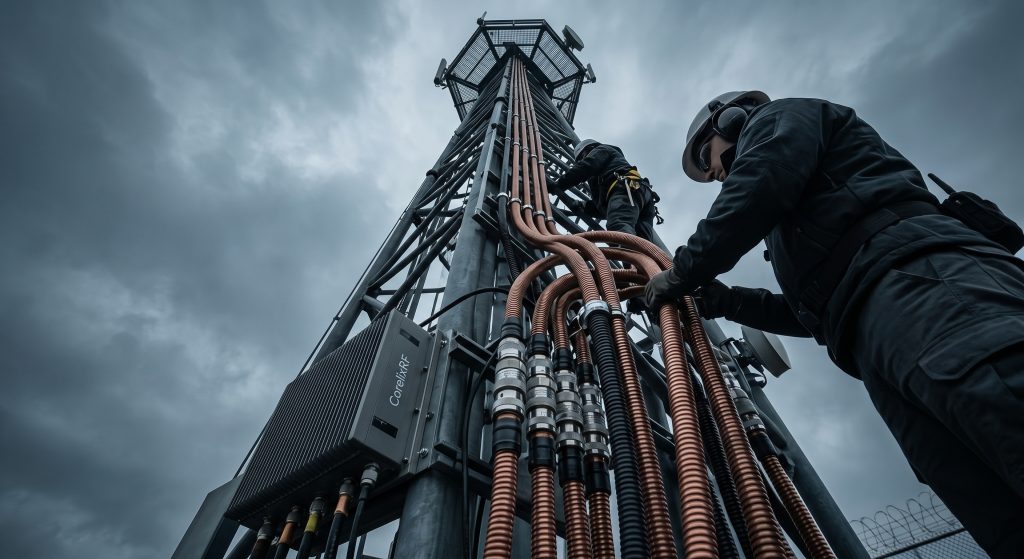
Consider the physical reality… Prison environments represent the most hostile deployment scenarios for sensitive microwave electronics outside of active military combat zones. The vertical integration requires heavy copper cables to traverse raw steel structural members subjected to extreme diurnal temperature shifts. These aggressive temperature variations cause the copper conductors and dielectric insulators within the transmission lines to expand and contract at completely different physical rates. Over a thirty-meter vertical run, this differential thermal expansion physically pushes the center conductor entirely out of the connector housing, severing the electrical connection. Furthermore, the RF environment around a modern correctional facility is heavily congested with multi-path reflections bouncing violently off concrete walls and steel perimeter fencing. The cabling system must not only strictly deliver the active RF payload but also maintain absolute shielding effectiveness to prevent self-oscillation and destructive feedback loops into the receiver modules. The transmission lines must be secured with specialized hoisting grips distributed evenly along the tower leg to disperse the mechanical load and prevent the outer conductor from buckling under its own aggregate weight.
How Do We Guarantee 100W RF Energy Truly Reaches the Antenna?
Let’s examine the raw data… High-Power Jamming System Cabling Standards: How to Ensure 100W RF Energy Truly Reaches the Antenna? requires strict adherence to laboratory-grade measurement techniques executed directly in the field. System integrators must utilize high-resolution Vector Network Analyzers (VNA) to actively sweep the entire transmission line assembly after physical installation but strictly prior to activating the power amplifier. Distance-to-fault (DTF) measurements will immediately pinpoint the precise locations of mechanical stress, connector deformation, or cable crushing caused by improperly tightened mounting hardware. CorelixRF severely mandates a maximum system return loss of 18 dB across the 5700-5900 MHz operating band. Anything measuring less strictly indicates a structural defect that will severely attenuate the forward power and generate dangerous hardware reflections. By utilizing low-loss air-dielectric cables and performing precision torque wrench tightening on every single junction, integration engineers effectively bypass the standard mechanical failure modes. This rigorous validation process guarantees that the 100W of raw RF power generated at the base station strictly maintains its amplitude, arriving at the antenna port with maximum density to completely overpower unauthorized drone control signals.
| System Validation Metric | Laboratory Specification | Field Installation Requirement | Verification Tool |
| Transmission Loss | < 1.0 dB Limit | Swept Validation | Vector Network Analyzer |
| Intermodulation | PIM < -150 dBc | Dynamic Impact Test | PIM Analyzer |
| Environmental Seal | IP67 Rating | IP68 with Butyl Tape | Pressure Integrity Test |
| Mating Torque | 25.0 Nm Target | Calibrated Wrench | Physical Inspection |
Why Is Thermal Expansion a Silent Killer in Microwave Systems?
The fundamental physics dictate… that all physical matter changes volume in direct response to thermal energy, and high-power microwave systems violently accelerate this natural degradation. When a 100W amplifier operates continuously in a 5.8 GHz defensive jamming role, the severe RF skin-effect heating adds significant internal thermal load directly to the transmission line. The outer jacket of a dark-colored coaxial cable baking in the summer sun can rapidly reach surface temperatures exceeding 80 degrees Celsius. The PTFE dielectric material softens heavily under this load, allowing the heavy copper center conductor to mechanically migrate off-center if the cable is bent beyond its minimum dynamic bend radius limit. This migration permanently alters the characteristic impedance from 50 ohms to highly unpredictable reactive values, ruining the voltage standing wave ratio completely. During the sudden atmospheric temperature drop at night, the internal materials contract violently. If the RF connectors are not fitted with specialized thermal-compensating spring contacts, the internal mating pins separate microscopically. CorelixRF directly accounts for these brutal thermodynamic cycles by specifying robust components strictly engineered with mathematically matched coefficients of thermal expansion, completely preventing the mechanical sheer forces that rapidly destroy typical commercial installations.
What Happens When Substandard Coaxial Dielectrics Break Down?
Here is the engineering truth… The specialized dielectric material separating the center conductor from the outer shield remains the most physically vulnerable component in any high-power transmission system. Cheap commercial cables utilize heavily aerated foam polyethylene simply to cut manufacturing costs and reduce shipping weight. Under continuous high-altitude ultraviolet radiation and extreme temperature cycling on a prison tower frame, this cheap foam undergoes rapid molecular outgassing and total structural collapse. Condensation moisture from high-humidity environments aggressively permeates through microscopic cracks in the degraded outer cable jacket, instantly changing the dielectric constant of the internal insulator. Because water is highly absorptive at microwave frequencies, it actively turns the coaxial cable into a massive dummy load that dissipates the 100W signal as boiling thermal heat rather than radiating it as defensive RF energy. The system insertion loss spikes exponentially, and the resulting radical phase shift completely destabilizes the entire jamming array. CorelixRF specifies the mandatory use of advanced closed-cell fluoropolymer dielectrics that remain chemically inert and structurally rigid regardless of the environmental brutality, ensuring absolute phase stability and zero moisture ingress over a twenty-year continuous operational lifespan.
How Does the CRF-PA-5700M5900M-100W Tolerate Severe Reflection?
Consider the physical reality… that even the most meticulously installed tower cabling will eventually mechanically degrade, meaning the power amplifier itself must possess heavy internal armor to survive the inevitable reflected energy. The CorelixRF CRF-PA-5700M5900M-100W is specifically designed to completely dominate in the 5.7 to 5.9 GHz spectrum, utilizing the latest-generation Gallium Nitride on Silicon Carbide (GaN-on-SiC) transistor technology. SiC substrates provide vastly superior thermal conductivity compared to standard silicon architecture, allowing the active die to extremely quickly dump transient heat spikes generated by physical impedance mismatches. Furthermore, the CorelixRF engineering team strictly integrates heavy-duty drop-in microstrip circulators rated for high peak envelope power directly at the final RF output stage. These specialized circulators act exactly as one-way mechanical valves, forcefully routing any reverse power returning from a heavily damaged tower cable directly into a heavy beryllium oxide termination resistor. This hardened hardware topology effectively ensures that even if a prison guard accidentally severs the main transmission line with a security vehicle, the CRF-PA-5700M5900M-100W will safely absorb its own massive 100W output without permanently destroying the critical semiconductor junctions.
| Hardware Parameter | CRF-PA-5700M5900M-100W Specification | Destructive Limit Condition | CorelixRF Protection Action |
| Operational Band | 5700 MHz – 5900 MHz | Out of Band Emission | Narrowband Isolator Blocking |
| Maximum Output | 50 dBm (100 Watts) | 50.5 dBm Peak | Hardware ALC Trigger |
| VSWR Tolerance | Infinite:1 (Short/Open) | Reflected 100W | Beryllium Oxide Dissipation |
| Baseplate Temp | -20°C to +65°C | +85°C Junction | Immediate Thermal Shutdown |
Can Laboratory VNA Data Predict Field Failure in Tower Deployments?
Let’s examine the raw data… Clean laboratory measurements clearly provide a structural baseline, but they completely fail to physically account for the dynamic mechanical variables heavily introduced during a vertical tower installation. A completed cable assembly might easily demonstrate a perfect 1.1:1 VSWR when coiled neatly on a testing bench inside a heavily climate-controlled engineering facility. However, once that exact same assembly is hauled fifty meters high into the atmosphere, strapped tightly to structural steel members, and subjected to continuous gale-force winds, the internal geometry physically deforms. System integrators must immediately adopt a strict methodology of active field-level characterization. High-frequency sweep testing must be performed post-installation utilizing a portable Vector Network Analyzer rigorously calibrated directly at the exact interface mating points. Engineers must actively look well beyond simple return loss values and deeply analyze the Phase Delay and Time Domain Reflectometry (TDR) plots to identify localized cable crimping or micro-fractures in the center copper conductor. CorelixRF rigidly mandates that all project commissioning documentation includes these post-installation field sweeps to completely guarantee the mechanical integrity of the transmission line strictly before the CRF-PA-5700M5900M-100W is ever powered on.
What Are the Exact Installation Tolerances for 5.8GHz Systems?
The fundamental physics dictate… that as operational frequency increases, the wavelength proportionally decreases, heavily making the entire system exponentially more sensitive to microscopic physical variations. At 5.8 GHz, the functional wavelength is roughly 51 millimeters. Even a connector misalignment of just two or three millimeters represents a highly significant fraction of the operational wavelength, instantly generating massive phase errors and destructive signal cancellation. Installation tolerances must be rigorously executed with strict machinist-level precision. Connectors must be mated utilizing heavily calibrated torque wrenches specifically matched to the connector geometry—typically 25 Nm for heavy 7/16 DIN interfaces—to actively compress the internal O-rings perfectly without crushing the center pin collet. The bend radius of the corrugated cable must never exceed the manufacturer’s absolute minimum dynamic limit, otherwise the internal copper corrugations will permanently buckle, creating a permanent capacitive bump in the transmission line. CorelixRF strictly emphasizes that high-power microwave integration is not standard electrical wiring; it is the absolute precision plumbing of invisible electromagnetic fields, requiring strict mechanical discipline to deliver maximum sustained power directly to the jamming antenna.
| Physical Tolerance | Minimum Requirement | Maximum Allowable Variance | Consequence of Failure |
| Mating Alignment | 0.00 mm Offset | 0.15 mm Deviation | Phase Cancellation |
| Center Pin Depth | Flush to Interface | 0.05 mm Recess | Capacitive Reactance Spike |
| Cable Bend Radius | > 250 mm Standard | Dynamic Limit Exceeded | Corrugation Buckling |
| Weather Sealing | 3 Layers Minimum | Air Gap Present | Instant Moisture Ingress |
How Do We Secure the Final Engineering Architecture?
The fundamental physics dictate… that the physical laws governing high-frequency electromagnetic propagation absolutely do not negotiate with poor mechanical integration. System integrators actively constructing prison jamming towers must totally abandon commercial-grade cabling components and strictly adopt absolute military-grade tolerances to prevent catastrophic system failure. Maintaining high-power microwave integrity is not a theoretical debate; it is a matter of absolute mechanical discipline, precision torque application, and utilizing robust GaN-on-SiC amplifier architecture. The CorelixRF CRF-PA-5700M5900M-100W physically provides the exact electronic durability required to reliably survive severe impedance mismatches and extreme thermal cycling in these highly hostile environments. By strictly controlling the transmission line physics from the baseplate to the tower top, engineers fully guarantee that the maximum amplitude of the generated RF energy securely reaches the radiating element. Contact the CorelixRF engineering team today to directly request the official Data Sheet for the CRF-PA-5700M5900M-100W and immediately secure the hardened physical hardware strictly required for your next high-power deployment.
What Are the Most Common Technical Questions Regarding 5.8GHz Tower Integration?
Let’s examine the raw data… When system integrators initiate the physical deployment phase of a secure prison jamming tower, they frequently encounter highly unforeseen mechanical and electrical challenges that deviate significantly from idealized laboratory conditions. The harsh physical reality of continuous outdoor operation in the 5700 MHz to 5900 MHz frequency band actively generates extreme stress on every single component in the RF transmission path. To successfully ensure the highest level of operational success and totally prevent catastrophic hardware failures, the CorelixRF engineering team has compiled rigorous technical data directly from active field deployment logs. The following specific inquiries represent the absolute most pressing technical concerns regarding impedance stability, thermal management, and power propagation. By deeply understanding these exact physical parameters and recognizing failure mechanisms, engineers can correctly implement the CRF-PA-5700M5900M-100W and physically guarantee that the defensive perimeter remains fully absolute against high-frequency drone threats.
Q1: Why does the CRF-PA-5700M5900M-100W use GaN-on-SiC instead of standard LDMOS?
At high operating frequencies strictly between 5700 MHz and 5900 MHz, standard LDMOS architecture aggressively suffers from severe parasitic capacitance and highly restrictive electron mobility, directly resulting in massive efficiency drops. CorelixRF strictly utilizes GaN-on-SiC because the heavy silicon carbide substrate directly provides superior thermal conductivity, rapidly moving transient heat away from the sensitive semiconductor junction during continuous 100W operation in extreme high-temperature outdoor environments.
Q2: How much return loss is physically acceptable in a prison tower jamming deployment?
CorelixRF strictly mandates an absolute minimum system return loss of 18 dB actively measured across the entire operational band. Any physical measurement worse than 18 dB clearly indicates a severe mechanical deformity directly in the transmission line or connector interface. This specific physical deformity will rapidly generate reflected power that heavily stresses the amplifier isolators and drastically reduces the effective radiated power of the defensive jamming signal.
Q3: Can we use standard braided LMR-400 coaxial cable for a thirty-meter vertical run?
No. Standard braided coaxial cables like LMR-400 structurally possess excessively high insertion loss strictly at 5.8 GHz. Actively pushing 100W directly through thirty meters of LMR-400 will physically result in the vast majority of your active RF energy converting into useless thermal heat. Engineers must strictly utilize rigid or semi-rigid corrugated copper cables to actively minimize dielectric losses and fully preserve the physical signal amplitude.
Q4: What specifically causes the precise 50-ohm connector geometry to fail over time?
Continuous heavy mechanical load aggressively applied from vertical copper cables, actively combined with high-frequency wind vibrations and diurnal temperature cycling, continuously exerts violent sheer stress directly on the connector housing. If standard brass connectors are physically used without highly precise torque application, the internal mating pins physically deform and microscopically separate. This structural failure instantly alters the system impedance, actively creating a massive VSWR spike.
Q5: How exactly does the internal isolator protect the CRF-PA-5700M5900M-100W?
The hardened CorelixRF hardware design tightly integrates high-power drop-in microstrip circulators strictly at the final amplification stage. If a heavy tower cable mechanically breaks or a connector physically fails, the forward 100W signal aggressively reflects backward toward the active amplifier. The circulator mechanically acts as a heavy directional valve, safely routing this highly destructive reverse energy directly into a highly robust beryllium oxide termination resistor, fully protecting the sensitive GaN transistors from thermal vaporization.
Authorized RF engineering and compliance review
For regulated RF systems, this page should be used as an engineering and compliance review path, not as a public deployment checklist. CorelixRF starts with authorization status, operating region, frequency plan, output limit, antenna interface, safety controls, thermal limits and acceptance documents.
- RFQ checklist – send the data buyers usually forget, including band, power, duty cycle, interface and test standard
- delivery documentation – check what documents can support incoming inspection, FAT review and long-term maintenance
- quality and certification review – review the quality and compliance evidence before the project moves into procurement
- RF front-end platform – compare the RF chain as a system instead of selecting one isolated module
- RF configurator – turn frequency, power, thermal and interface requirements into a first configuration brief
- case studies – review similar engineering paths before sending an RFQ
- engineering contact – send the application notes, block diagram or target specification to engineering sales
This keeps the discussion inside lawful, authorized RF programs while still giving procurement teams a clear way to request amplifier, antenna, SDR source, documentation and factory review.
RF Cabling Review Path for High-Power Sites
For high-power RF cabling projects, review cable loss, connector heating and load condition together with the RF power amplifier platform options and RF front-end platform planning. Send the band, output power, duty cycle and acceptance evidence needs through the RF inquiry form for engineering review.