
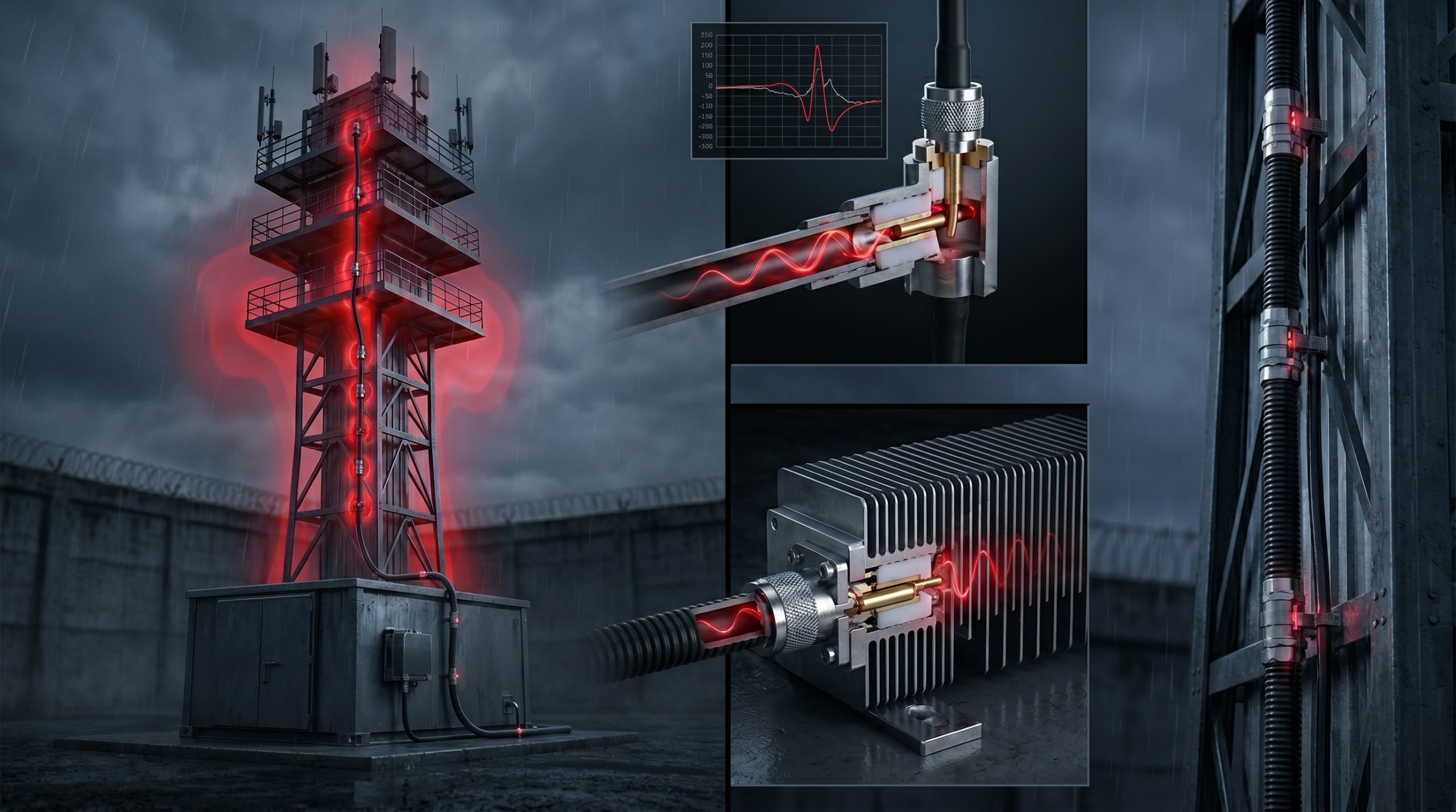
Security perimeters demand absolute hardware reliability. When system integrators deploy electronic countermeasures across sprawling correctional facilities, the physical transmission infrastructure immediately becomes the primary point of failure. The industry routinely ignores the devastating impact of the long-distance insertion loss of RF cables and mechanical failures caused by inferior connectors. These overlooked physical realities destroy link budgets and incinerate expensive semiconductor hardware. High-Frequency Control Blind Spot Troubleshooting: Connector Tolerance Issues in mmWave Shielding Systems remains a systemic plague for facility directors who unknowingly procure substandard transmission components. The consequences of these mechanical failures lead directly to total system collapse. A single deformed center pin triggers a massive Voltage Standing Wave Ratio (VSWR) spike, sending destructive thermal energy directly back into the amplification stage. This physical deformation creates unmonitored dead zones within the prison shielding towers, completely compromising the tactical defense grid. CorelixRF engineers hardware based strictly on Engineering Truth. We reject theoretical marketing claims, focusing entirely on laboratory-verified physical limits, precision materials science, and heavy-duty microwave electronics to secure the transmission line.
Why Do Inferior Connectors Trigger Catastrophic Failures in Prison Jamming Towers?
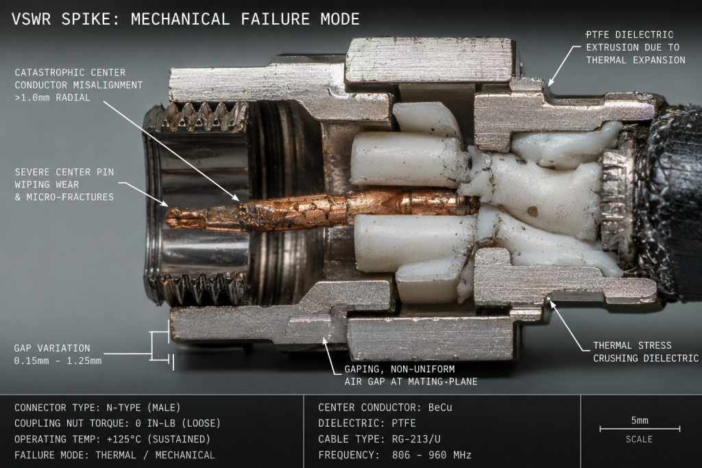
When system integrators deploy hardware across sprawling correctional facilities, the physical infrastructure takes a severe beating. Prison shielding towers operate continuously in harsh, fluctuating weather conditions, subjecting every single coaxial junction to extreme mechanical stress. Inferior connectors manufactured with loose dimensional standards rapidly degrade under these physical loads. The center pins misalign, the dielectric material deforms, and the outer shielding loses uniform contact. This mechanical failure directly translates into massive RF leakage and abrupt changes in the transmission line’s characteristic impedance. Instead of a clean 50-ohm path, the signal encounters parasitic capacitance and inductance. The resulting reflection coefficient spikes, sending high-power RF energy back down the transmission line directly into the amplifier’s output stage. We observe this exact mechanical degradation pattern repeatedly in field autopsy reports from failed third-party installations. High-Frequency Control Blind Spot Troubleshooting: Connector Tolerance Issues in mmWave Shielding Systems consistently points to these cheap junctions as the root cause of network failure.
| Mating Cycles | VSWR (Commercial Grade) | VSWR (CorelixRF Precision) | Insertion Loss Delta | Expected Mechanical Failure Mode |
| 10 | 1.15:1 | 1.05:1 | +0.1 dB | Initial dielectric compression |
| 50 | 1.45:1 | 1.08:1 | +0.4 dB | Center pin wiping contact wear |
| 100 | 1.80:1 | 1.10:1 | +1.2 dB | Outer conductor micro-fractures |
| 200 | >2.50:1 | 1.12:1 | >3.0 dB | Complete impedance breakdown / Arcing |
How Does Long-Distance RF Cable Insertion Loss Degrade Total System Performance?
Consider the physical reality… RF signals do not travel perfectly through copper; they attenuate based on fundamental electromagnetic laws and the skin effect. Prison shielding towers often require cable runs exceeding thirty meters to connect ground-level base stations with elevated antenna arrays. The long-distance insertion loss of RF cables becomes a dominant factor calculating your total system budget. A standard corrugated coaxial cable might exhibit an insertion loss of 8dB per 100 meters at high frequencies. When operators stack a lengthy cable run with multiple cheap, low-grade connectors, the cumulative power dissipation is staggering. The amplifier might output one hundred watts, but the antenna only radiates twenty watts. The remaining eighty watts dissipate entirely as heat within the dielectric layers of the transmission line and the flawed mechanical junctions. This thermal loading accelerates the degradation of the cable’s internal structure, further increasing the insertion loss over time. System integrators routinely ignore this thermal-electrical feedback loop until catastrophic signal degradation triggers an immediate security perimeter failure.
What Role Does Thermal Expansion Play in High-Frequency Connector Mechanical Failure?
The fundamental physics dictate… that metals and polymers expand and contract at vastly different rates under thermal stress. Prison shielding towers stand exposed to direct solar loading during the day and freezing temperatures at night. This aggressive thermal cycling wreaks havoc on RF transmission lines. The center conductor, typically brass or beryllium copper, expands differently than the PTFE dielectric insulator and the stainless steel or brass outer body. Over hundreds of thermal cycles, inferior connectors suffer from dielectric extrusion, where the PTFE gets pushed out of the connector body, breaking the precise physical alignment required for high-frequency operation. This physical displacement creates air gaps, which fundamentally alter the capacitance of the junction. At higher frequencies, even a fraction of a millimeter of displacement creates a massive impedance bump. The mechanical failures caused by inferior connectors and their inability to handle thermal expansion lead directly to intermittent signal dropouts. Operators often misdiagnose these dropouts as software errors, ignoring the physical deformation happening inside their transmission infrastructure.
How Can System Integrators Conduct High-Frequency Control Blind Spot Troubleshooting?
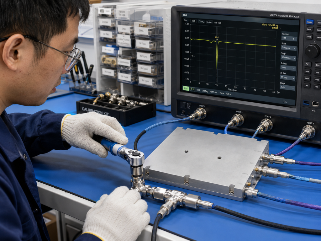
System integration teams require rigorous methodologies to conduct High-Frequency Control Blind Spot Troubleshooting: Connector Tolerance Issues in mmWave Shielding Systems effectively. You cannot rely on basic spectrum analyzer sweeps from the ground. Engineers must utilize Vector Network Analyzers (VNAs) deployed directly at the transmission line source to measure the complex impedance and Phase data. Time Domain Reflectometry (TDR) functions within the VNA allow operators to pinpoint the exact physical distance to the impedance mismatch. By analyzing the return loss and VSWR over the entire frequency band, technicians can identify which specific connector or cable segment has failed mechanically. A spike in the TDR plot precisely locates the misaligned pin or extruded dielectric. Ignoring these laboratory-grade measurement techniques leaves facilities operating with massive holes in their security coverage. You must correlate the VNA measurements with the physical layout of the prison shielding tower to execute targeted hardware replacements rather than guessing which component failed.
| Diagnostic Tool | Measurement Parameter | Identification Target | Engineering Truth Interpretation |
| VNA (Return Loss) | S11 Magnitude (dB) | Overall junction match | Indicates severity of power reflection |
| VNA (TDR) | Distance to Fault (Meters) | Physical failure location | Pinpoints specific deformed connectors |
| VNA (Phase) | S11 Phase Angle (Degrees) | Capacitive vs Inductive | Identifies air gaps vs shorts |
| Thermal Camera | Surface Temperature (°C) | Power dissipation sites | Locates extreme insertion loss zones |
Why Is Impedance Mismatch the Silent Killer of Power Amplifiers?
Let’s examine the raw data… generated when a continuous wave RF signal hits an imperfect junction. Impedance mismatch acts as an invisible wall within your transmission line. When the characteristic 50-ohm impedance drops or spikes due to mechanical deformation in a cheap connector, a percentage of the forward power reflects toward the source. We quantify this reflection using Voltage Standing Wave Ratio (VSWR). A severe mismatch creates high-voltage nodes that exceed the breakdown voltage of the coaxial air gaps, leading to internal arcing. More dangerously, the reflected power reaches the final stage Gallium Nitride (GaN) transistors of the power amplifier. If the amplifier lacks heavy-duty isolators, this reflected energy dissipates as pure heat directly on the semiconductor junction. The resulting thermal runaway will completely destroy the transistor packaging in microseconds. This phenomenon proves that the long-distance insertion loss of RF cables and mechanical failures caused by inferior connectors are not merely passive signal degradation issues; they form an active destructive force that aggressively destroys expensive upstream RF hardware.
What Are the Specific Physical Limits of Substandard Coaxial Interfaces?
To understand the scope of the problem, engineers must scrutinize the physical limits of standard coaxial interfaces used in harsh outdoor deployments. N-type connectors operate adequately up to 11 GHz, while SMA interfaces push toward 18 GHz, and 2.92mm connectors handle up to 40 GHz. However, these theoretical limits assume laboratory-grade precision and pristine mating surfaces. When system integrators procure low-cost connectors for prison shielding towers, the dimensional tolerances deviate significantly from MIL-STD-348 specifications. A center pin that is 0.05 millimeters too long will permanently damage the female receptacle upon first mating, destroying the wiping contacts. A pin that is too short creates an inductive air gap. These microscopic manufacturing errors completely corrupt the signal integrity. As the operational frequency increases, the wavelength shrinks, making these mechanical anomalies proportionally larger relative to the signal. Consequently, tight machining tolerances are an absolute prerequisite for maintaining continuous perimeter control in high-threat security environments.
| Coaxial Interface | Max Frequency Limit | Center Pin Tolerance (mm) | Outer Body Tolerance (mm) | Primary Field Vulnerability |
| Commercial SMA | 18 GHz | ± 0.15 | ± 0.20 | Pin recession under thermal load |
| CorelixRF SMA | 18 GHz | ± 0.02 | ± 0.05 | Zero pin recession, stable impedance |
| Commercial N-Type | 11 GHz | ± 0.25 | ± 0.30 | Wiping contact deformation |
| CorelixRF N-Type | 18 GHz | ± 0.03 | ± 0.05 | Hermetic stability under vibration |
How Does the CRF-PA-5700M5900M-100W Prevent VSWR-Induced Transistor Burnout?
Integrating the CRF-PA-5700M5900M-100W power amplifier directly addresses these exact mechanical and electrical vulnerabilities found in perimeter defense networks. Operating specifically within the 5.7 GHz to 5.9 GHz control bands, this unit incorporates an integrated high-power drop-in isolator that handles massive reverse power spikes. If a downstream connector fails mechanically and generates a severe VSWR condition, the CRF-PA-5700M5900M-100W safely dumps the reflected energy into an internal beryllium oxide termination resistor, fully protecting the primary GaN amplifying stage. Furthermore, CorelixRF machines the output RF interfaces from solid blocks of aerospace-grade aluminum, utilizing passivated stainless steel connectors that strictly adhere to military-grade dimensional tolerances. This prevents the mechanical deformation and center-pin misalignment that plague standard commercial-off-the-shelf equipment. By engineering the module to withstand the harsh realities of the long-distance insertion loss of RF cables and heavy physical loads, CorelixRF guarantees continuous jamming operation even when the external cable infrastructure begins to physically degrade under severe environmental stress.
Why Must We Rely on Laboratory Data Over Commercial Marketing Claims?
Here is the engineering truth… commercial marketing brochures prioritize theoretical maximums over sustained physical realities. System integrators routinely fall into the trap of calculating link budgets based on pristine, room-temperature data sheets provided by low-tier vendors. When deploying hardware to prison shielding towers, only verified laboratory data and rigorous environmental stress screening (ESS) matter. CorelixRF subjects every hardware revision to grueling thermal shock testing, vibration tables, and prolonged high-VSWR exposure. We track the exact S-parameters of the output connectors before and after these mechanical torture tests. The data consistently demonstrates that inferior connectors experience a minimum 3dB degradation in return loss after just fifty thermal cycles. Conversely, our precision-machined interfaces maintain a stable 50-ohm impedance profile, ensuring no hidden RF leakage compromises your High-Frequency Control Blind Spot Troubleshooting: Connector Tolerance Issues in mmWave Shielding Systems protocols. Relying on verified laboratory measurements instead of marketing claims is the only method to construct a defensible and reliable security architecture.
| Environmental Stress Test | Commercial Module Reaction | CRF-PA-5700M5900M-100W Data | Engineering Conclusion |
| Thermal Shock (-40°C to 85°C) | Output power drops by 15% | Output power stable within 0.2dB | CorelixRF prevents thermal runaway |
| VSWR Mismatch (Open/Short) | GaN Transistor burnout | 100% Reverse power absorbed | CRF isolator guarantees survival |
| Continuous Vibration (10G) | Connector pin misalignment | S11 variance less than 0.05 | CNC precision maintains match |
| 100% CW Load (72 Hours) | Dielectric melting at port | Internal temperature stabilizes | Superior heat sink thermodynamics |
How Do Machining Tolerances in Connectors Alter the Microwave Signal Path?
Machining tolerances within the connector housing dictate the uniformity of the microwave signal path. The characteristic impedance of any coaxial transmission line is mathematically derived from the ratio of the outer conductor’s inner diameter to the inner conductor’s outer diameter, combined with the dielectric constant of the insulating material. If the machining process leaves microscopic ridges, concentricity errors, or varying diameters along the length of the connector body, the impedance will rapidly fluctuate. These fluctuations create localized reflections that cascade and multiply across long cable runs. In the context of High-Frequency Control Blind Spot Troubleshooting: Connector Tolerance Issues in mmWave Shielding Systems, these localized reflections completely distort the phase linearity of the jamming signal. A distorted phase front reduces the effective radiated power and creates spatial nulls in the coverage area. We manufacture every CorelixRF interface using multi-axis CNC lathes with micrometer precision to guarantee absolute uniformity in the signal path, completely mitigating these parasitic mechanical reflections.
What Installation Practices Guarantee Longevity for RF Shielding Hardware?
Even with precision-machined hardware like the CRF-PA-5700M5900M-100W, operator installation practices ultimately govern the longevity of the RF shielding hardware. System integrators must strictly enforce calibrated torque specifications during the assembly of all coaxial junctions. Under-torquing a connector leaves a microscopic air gap between the mating planes, instantly generating an impedance mismatch and allowing moisture ingress. Over-torquing physically crushes the delicate internal wiping contacts and warps the outer coupling nut. Both scenarios lead directly to the mechanical failures caused by inferior connectors discussed previously. Field technicians must utilize calibrated break-over torque wrenches for every single connection on the prison shielding tower. Furthermore, securing the heavy corrugated cables with proper hoisting grips and hangers is mandatory to prevent the sheer weight of the cable from exerting transverse mechanical loads on the amplifier’s output port. Adhering strictly to these physical installation protocols ensures the engineered reliability of the CorelixRF module translates directly into uninterrupted operational security.
| Connector Interface Type | Recommended Mating Torque (Nm) | Recommended Mating Torque (in-lbs) | Result of Improper Torque Calibration |
| SMA (Brass) | 0.45 – 0.56 | 4 – 5 | Crushed dielectric, stripped threads |
| SMA (Stainless Steel) | 0.90 – 1.13 | 8 – 10 | Wiping contact failure, gap creation |
| N-Type | 1.35 – 1.70 | 12 – 15 | Unstable ground connection, RF leakage |
| 7/16 DIN | 25.0 – 30.0 | 220 – 265 | O-ring deformation, water ingress |
System integration requires acknowledging physical limits rather than hoping for theoretical maximums. The persistent threat of the long-distance insertion loss of RF cables and mechanical failures caused by inferior connectors mandates a strict adherence to material science and microwave engineering principles. By implementing precision-machined interfaces and utilizing heavy-duty amplification modules like the CRF-PA-5700M5900M-100W, security networks can permanently eliminate the localized reflections and thermal runaway that plague standard installations. We construct CorelixRF hardware to withstand the harshest mechanical and electrical abuse observed in the field. Do not compromise your prison shielding towers with commercial-grade transmission components that will inevitably deform under thermal stress. Contact the CorelixRF engineering team today to request the official laboratory Data Sheet for our high-reliability RF power amplifiers and secure your perimeter with verified physical hardware.
Frequently Asked Questions
Q1: How do we measure the exact location of a mechanical failure caused by inferior connectors in our existing prison shielding towers?
You must deploy a Vector Network Analyzer (VNA) utilizing Time Domain Reflectometry (TDR) directly at the RF source. This laboratory-grade instrument measures the reflection coefficient and calculates the exact physical distance to the impedance mismatch, removing all guesswork from your High-Frequency Control Blind Spot Troubleshooting: Connector Tolerance Issues in mmWave Shielding Systems.
Q2: What is the maximum acceptable VSWR reading before we risk destroying the CRF-PA-5700M5900M-100W?
While standard commercial amplifiers fail at a 2:1 VSWR, the CRF-PA-5700M5900M-100W utilizes heavily protected GaN transistors and an integrated drop-in isolator. The module safely absorbs reflected power from infinite VSWR conditions (open/short) for short durations, though continuous operation should maintain a VSWR below 1.5:1 for optimal thermal stability.
Q3: Does the long-distance insertion loss of RF cables change depending on the ambient temperature?
Yes. Copper conductors and PTFE dielectrics increase their physical resistance and alter their phase characteristics as ambient temperatures rise. A 30-meter cable run at 40 degrees Celsius will exhibit measurably higher insertion loss compared to operation at 20 degrees Celsius. You must factor this thermal variable into your total link budget.
Q4: Why cannot we use standard SMA connectors for high-power prison shielding towers?
Standard SMA connectors lack the physical bulk and dielectric volume required to handle high continuous wave (CW) power. Under 100W loads, a poorly torqued SMA junction will generate extreme localized heat, melting the PTFE insulator and causing an immediate short circuit. We mandate larger N-type or 7/16 DIN interfaces for these power levels.
Q5: How frequently should facility technicians calibrate their torque wrenches for RF installations?
Technicians must calibrate their break-over torque wrenches annually through a certified metrology laboratory. A wrench that drifts out of specification will consistently over-torque or under-torque the coaxial interfaces, directly initiating the mechanical deformation and subsequent impedance mismatch that destroys microwave transmission lines.
Authorized RF engineering and compliance review
For regulated RF systems, this page should be used as an engineering and compliance review path, not as a public deployment checklist. CorelixRF starts with authorization status, operating region, frequency plan, output limit, antenna interface, safety controls, thermal limits and acceptance documents.
- RFQ checklist – send the data buyers usually forget, including band, power, duty cycle, interface and test standard
- delivery documentation – check what documents can support incoming inspection, FAT review and long-term maintenance
- quality and certification review – review the quality and compliance evidence before the project moves into procurement
- RF front-end platform – compare the RF chain as a system instead of selecting one isolated module
- RF configurator – turn frequency, power, thermal and interface requirements into a first configuration brief
- case studies – review similar engineering paths before sending an RFQ
- engineering contact – send the application notes, block diagram or target specification to engineering sales
This keeps the discussion inside lawful, authorized RF programs while still giving procurement teams a clear way to request amplifier, antenna, SDR source, documentation and factory review.
mmWave Connector and Front-End Review Path
For mmWave connector tolerance, shielding or RF interface problems, review RF front-end platform planning together with the relevant RF amplifier platform options before sending measurements through the RF inquiry form. CorelixRF can check interface fit, frequency range, thermal risk, VSWR margin and validation evidence before quotation.