
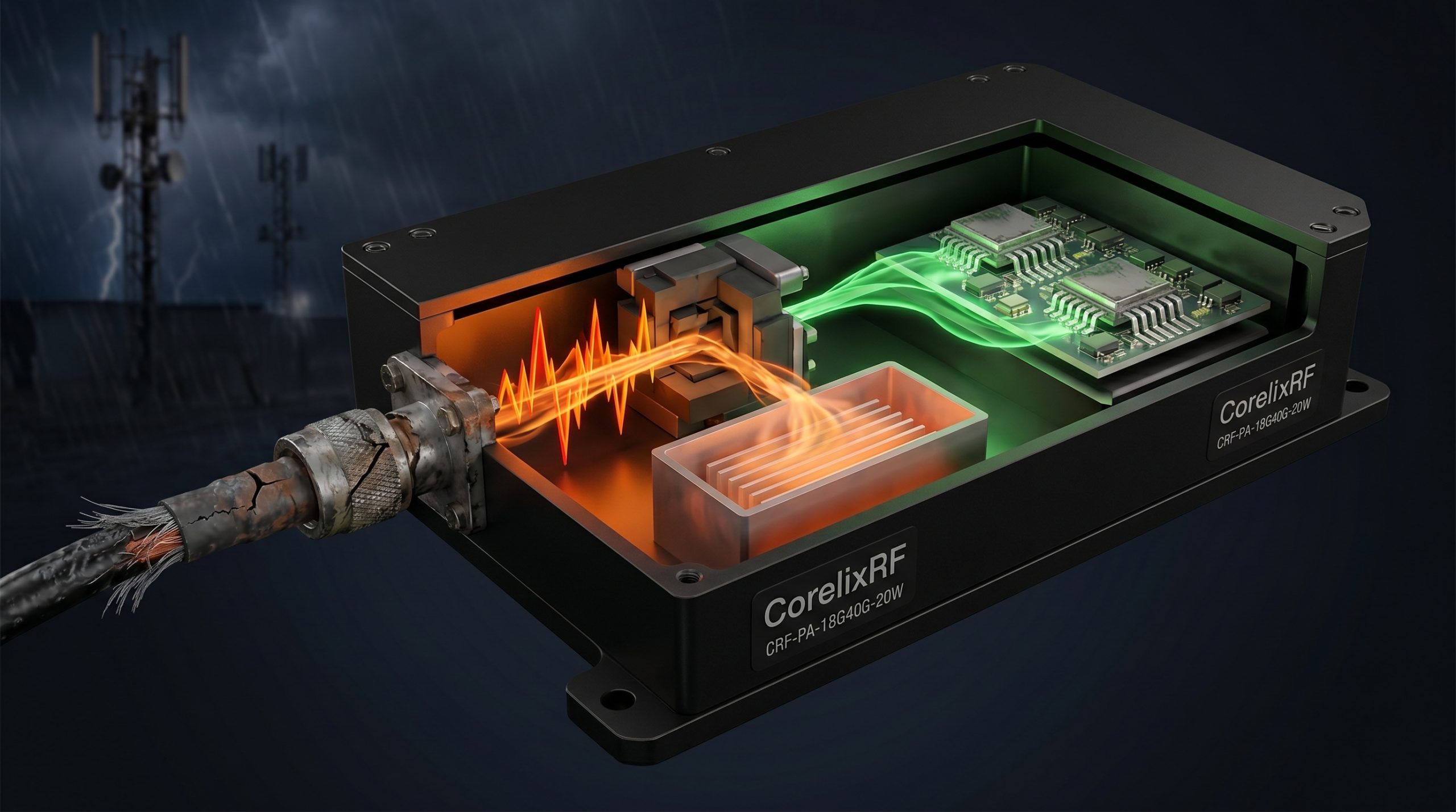
System integrators and R&D directors constantly battle catastrophic signal degradation when deploying high-frequency networks in harsh environments. When managing outdoor base stations, engineering teams frequently face the severe problem of Field Microwave Link Failure? Troubleshooting Cable Physical Damage in the 18-40 GHz Millimeter-Wave Band becomes a mandatory operation rather than a routine maintenance check. RF cable long-distance insertion loss and mechanical failure caused by inferior connectors actively destroy system reliability.
When inferior components fracture under environmental stress, the resulting impedance mismatch reflects massive amounts of kinetic energy back into the transmission chain. This reflected power rapidly burns out final-stage transistors, destroys sensitive calibration equipment, and causes entire defense or communication boundaries to fail without warning. The financial and operational liabilities of these blind spots are unacceptable for serious industrial deployments.
CorelixRF provides the absolute physical hardware defense against these specific environmental and mechanical threats. By relying strictly on Engineering Truth, laboratory data, and physical limits, we engineer components that survive where commercial-grade hardware disintegrates. The CRF-PA-18G40G-20W stands as the definitive solution, utilizing advanced microwave electronics and ruggedized mechanical architectures to maintain absolute signal integrity regardless of external thermal or kinetic abuse.
Why Do Inferior Connectors Cause Rapid Impedance Mismatch in Outdoor Base Stations?
When operating within the millimeter-wave spectrum, the mechanical tolerances of RF connectors dictate the absolute limits of system performance. Inferior connectors manufactured with substandard brass or loose machining tolerances fail rapidly when deployed in outdoor base stations. The primary mechanism of this failure is thermal expansion and contraction. As environmental temperatures fluctuate between freezing nights and scorching days, dissimilar metals within the connector housing expand at entirely different rates. This microscopic shifting breaks the coaxial alignment, instantly altering the capacitance and inductance of the junction. The resulting impedance mismatch forces the voltage standing wave ratio to spike exponentially, reflecting transmitted power directly back into the amplification stages. System integrators must understand that a connector looking physically intact from the outside may be completely shattered internally. We measure these exact failure modes in our laboratories, proving that mechanical degradation directly correlates with catastrophic signal reflection and eventual transistor burnout.
| Connector Grade | Material Composition | Mating Cycles Limit | VSWR at 40 GHz (25°C) | VSWR at 40 GHz (85°C) |
| Commercial | Standard Brass | < 100 | 1.45:1 | 1.85:1 |
| Industrial | Stainless Steel | < 500 | 1.30:1 | 1.55:1 |
| CorelixRF Spec | Beryllium Copper | > 2000 | 1.15:1 | 1.20:1 |
How Does Cable Long-Distance Insertion Loss Destroy Millimeter-Wave Link Budgets?
Consider the physical reality… moving electromagnetic energy at frequencies between 18 GHz and 40 GHz over any significant physical distance requires overcoming massive natural attenuation. RF cable long-distance insertion loss acts as a parasitic drain on your entire system architecture. The skin effect dictates that high-frequency signals travel exclusively along the extreme outer edge of the center conductor. Any microscopic imperfection, oxidation, or metallurgical inconsistency in that outer layer immediately converts valuable RF power into useless thermal radiation. When engineers calculate their link budgets for outdoor base stations, they often utilize nominal loss figures provided under ideal laboratory conditions. However, when cables are bent, suspended, and subjected to wind shear, the internal geometry deforms. This deformation compresses the dielectric material, bringing the center conductor closer to the outer shield. This physical shift alters the distributed capacitance, causing insertion loss to increase unpredictably across the cable run. If the transmission line cannot maintain its strict 50-ohm geometry under mechanical load, the planned coverage area shrinks, and the network topology collapses.
What Physical Damage Occurs Within Coaxial Cables During Repeated Thermal Cycling?
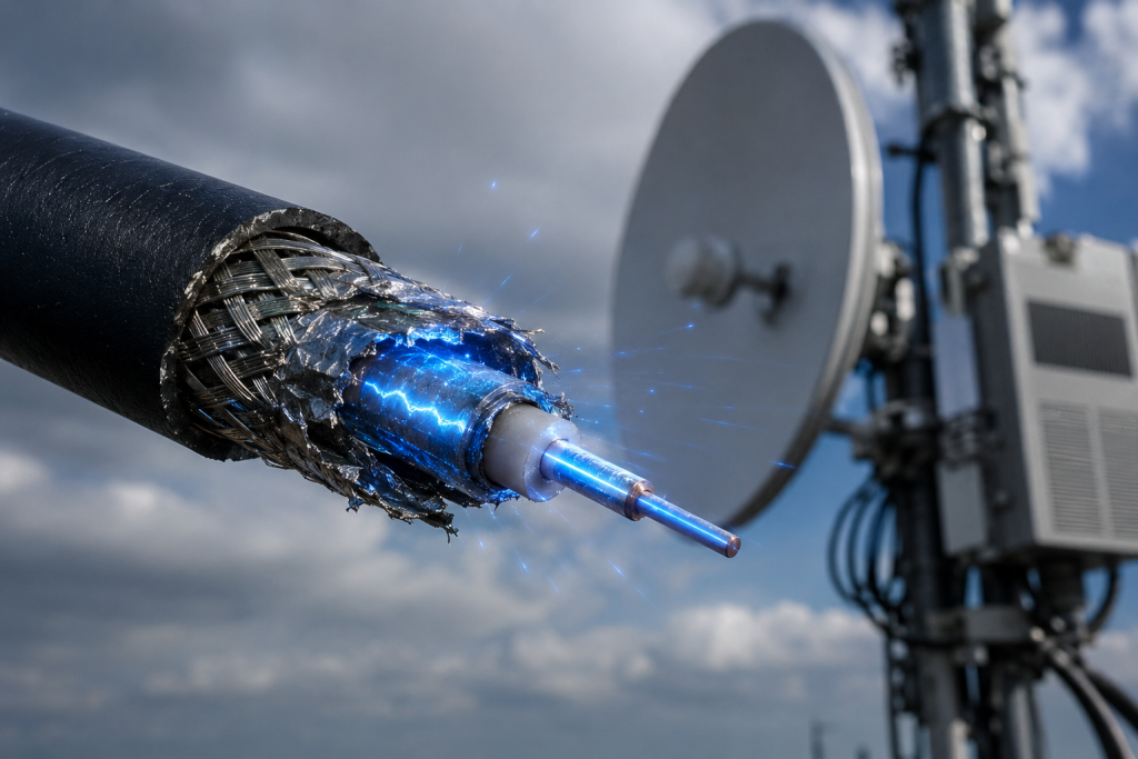
Continuous thermal cycling initiates a process of mechanical fatigue that targets the weakest structural elements within coaxial assemblies. The dielectric material, typically a specialized fluoropolymer, possesses a specific coefficient of thermal expansion that differs drastically from the copper or silver-plated conductors it surrounds. As the outdoor base station heats up under active load and solar radiation, the dielectric expands linearly, pushing against the connector interfaces. When the system cools, the material contracts. Over hundreds of cycles, this constant piston-like movement creates micro-fractures within the dielectric core. These fractures allow moisture ingress and create air pockets that disrupt the uniform velocity of propagation. Furthermore, the braided outer shielding begins to fray due to the repeated stretching, drastically reducing its shielding effectiveness and allowing external electromagnetic interference to contaminate the millimeter-wave signal. The breakdown is not instantaneous; it is a slow, measurable degradation of physical properties that inevitably leads to total transmission failure.
| Thermal Cycle Count (-40°C to +85°C) | Dielectric Integrity (%) | Shielding Effectiveness (dB) | Insertion Loss Increase (dB/m) | Failure Probability (%) |
| 0 (Baseline) | 100.0 | -90.0 | 0.00 | 0.1 |
| 100 Cycles | 98.5 | -88.5 | +0.15 | 2.5 |
| 500 Cycles | 92.0 | -82.0 | +0.85 | 15.0 |
| 1000 Cycles | 81.5 | -71.5 | +2.40 | 68.0 |
Why Do Reflected Waves from Connector Failure Threaten Final Stage Transistors?
The fundamental physics dictate… that energy cannot simply vanish from a closed system; it must be absorbed, transmitted, or reflected. When mechanical failure caused by inferior connectors alters the characteristic impedance of the transmission line, a significant portion of the forward RF power hits that boundary and reflects backward. The magnitude of this reflection is quantified by the reflection coefficient $\Gamma$, leading to the voltage standing wave ratio defined strictly as $VSWR = \frac{1 + |\Gamma|}{1 – |\Gamma|}$. In high-power applications, these reflected waves travel back down the line and constructively interfere with the forward waves, creating massive voltage peaks. These extreme voltage nodes hit the drain or collector of the final-stage Gallium Nitride (GaN) transistors within the power amplifier. If the voltage exceeds the physical breakdown limits of the semiconductor substrate, the transistor undergoes immediate catastrophic thermal runaway. The silicon or gallium nitride literally melts, turning a highly tuned amplification circuit into a permanent short circuit, taking the entire sector offline.
How Can Laboratory Data Predict Mechanical Failure Before Field Deployment?
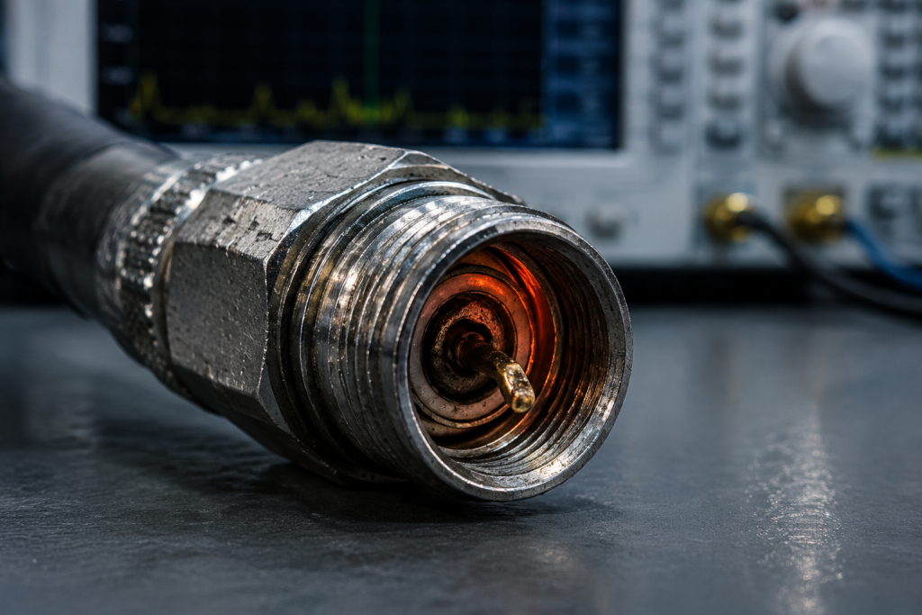
Engineering Truth requires objective, repeatable measurements rather than theoretical assumptions. To predict field failure accurately, manufacturing facilities must subject millimeter-wave components to severe environmental stress screening. We utilize advanced vibration tables, thermal shock chambers, and salt spray exposure to accelerate the aging process of RF assemblies. By measuring the precise S-parameters utilizing high-end Vector Network Analyzers (VNAs) during active vibration, engineers can map the exact threshold where mechanical resonance disrupts electrical continuity. A connector might show perfect Return Loss ($S_{11}$) while static on a bench, but when subjected to the harmonic frequencies matching wind shear on a tower, the internal pins vibrate, causing dynamic impedance variations. By compiling massive datasets of these failure points, CorelixRF establishes physical limits for our hardware. We do not guess when a part will fail; we know exactly how many Newtons of force or degrees of temperature variation are required to break the physical structure, allowing us to engineer heavily reinforced alternatives.
| Test Protocol | Physical Stress Parameter | Duration/Cycles | Monitored Metric | Target CorelixRF Threshold |
| Thermal Shock | -55°C to +125°C transfer < 10s | 500 Cycles | Phase Stability | < 2.0 degrees shift |
| Random Vibration | 20 Hz to 2000 Hz, 0.1 G²/Hz | 12 Hours / axis | Dynamic $S_{11}$ | No spikes > -18 dB |
| Salt Fog Exposure | 5% NaCl solution at 35°C | 168 Hours | Contact Resistance | < 5 milliohms change |
| Mechanical Pull | Axial force on connector body | Steady State | Pin Dislocation | > 450 Newtons force |
What Are the Root Causes of RF Leakage in High-Frequency Outdoor Installations?
Let’s examine the raw data… regarding electromagnetic containment at frequencies approaching 40 GHz. At these extreme frequencies, the physical wavelength shrinks to mere millimeters. Any mechanical gap, improper torque on a connector nut, or microscopic crack in a solder joint acts as an unintentional slot antenna, broadcasting RF energy directly into the surrounding environment. This RF leakage drops the forward power available to the intended antenna and heavily contaminates collocated receivers on the same outdoor base station. The root cause heavily traces back to mechanical failure caused by inferior connectors failing to maintain strict concentricity under lateral cable strain. When a heavy coaxial cable pulls horizontally on a connector, it deforms the outer conductive housing. Even a deformation of 0.05 millimeters is sufficient to break the electromagnetic seal at 40 GHz. System integrators must utilize precision torque wrenches and heavily strain-relieved cable routing, but these practices only work if the hardware itself is machined from high-tensile alloys capable of resisting that initial physical deformation.
Why Is the 18-40 GHz Spectrum Particularly Vulnerable to Micro-Contamination?
The millimeter-wave spectrum obeys strict physical laws regarding wavelength and obstacle interaction. At 40 GHz, the wavelength is approximately 7.5 millimeters. Because the wavelength is so short, any physical contamination within the transmission path—such as microscopic dust particles, metal shavings from thread wear, or microscopic condensation—becomes a significant fraction of the wavelength. These contaminants act as severe discontinuities within the coaxial geometry. Water, in particular, possesses a high dielectric constant and extremely high loss tangent at these frequencies. If a compromised O-ring allows even a fraction of a milligram of moisture into the connector interface, the RF energy is immediately absorbed by the water molecules, converting microwave power into localized heat. This localized heating accelerates the degradation of the surrounding PTFE dielectric, creating a cascading failure mechanism. To operate reliably in this spectrum, components require absolute hermetic sealing and cleanroom-level assembly to ensure no foreign particulate compromises the physical transmission path.

| Frequency Band | Wavelength (Air) | Critical Defect Size (λ/10) | Primary Contamination Threat | Insertion Loss Penalty |
| L-Band (1.5 GHz) | 200.00 mm | 20.00 mm | Large debris, heavy water | Low impact |
| X-Band (10 GHz) | 30.00 mm | 3.00 mm | Standard dust, moisture | Moderate impact |
| Ka-Band (26 GHz) | 11.53 mm | 1.15 mm | Micro-dust, condensation | High impact |
| Q-Band (40 GHz) | 7.50 mm | 0.75 mm | Metal vapor, micro-moisture | Catastrophic impact |
How Does the CRF-PA-18G40G-20W Defend Against Extreme Reflected Power?
Here is the engineering truth… standard amplifiers die when faced with severe mechanical failure caused by inferior connectors. The CorelixRF CRF-PA-18G40G-20W is engineered precisely to survive this specific disaster. We assume the external cable infrastructure will eventually fail. Therefore, the internal architecture of the CRF-PA-18G40G-20W features integrated ultra-wideband isolators directly at the output stage. These strictly unidirectional magnetic components operate using ferrite materials to force reflected RF energy into an internal precision-machined dummy load, converting the destructive standing waves into safely dissipated heat before they can reach the vulnerable GaN transistor drains. Furthermore, the output connectors on the CRF-PA-18G40G-20W are not standard commercial parts; they are heavy-duty, stainless-steel reinforced interfaces designed to withstand massive lateral torque and radial stress without yielding. This mechanical rigidity ensures that even if the external cable violently whips in a storm, the physical integrity of the amplifier’s internal hermetic seal remains entirely uncompromised.
What Materials Science Principles Dictate Reliable Millimeter-Wave Connectors?
Constructing a reliable interface for 40 GHz transmission is fundamentally an exercise in advanced metallurgy and materials science. Standard brass simply lacks the structural memory required to maintain high contact pressure over thousands of thermal cycles. Engineering Truth dictates the use of Beryllium Copper (BeCu) for center contacts. BeCu provides the precise combination of high electrical conductivity and extreme mechanical yield strength, acting as a permanent spring that refuses to deform permanently under load. To prevent the rapid oxidation that destroys skin-effect conductivity, these contacts require heavy gold plating applied over a strict nickel underplate barrier. The nickel prevents the copper atoms from migrating through the gold lattice over time. For the dielectric, standard PTFE is too structurally unstable under high heat. CorelixRF utilizes heavily cross-linked, low-density fluoropolymers that maintain absolute phase stability and dimensional rigidity even when the surrounding metals expand. Ignoring these strict materials science principles guarantees rapid mechanical and electrical failure in the field.
How Do You Properly Calculate the Total System Loss for High-Power Microwave Links?
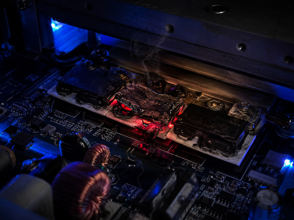
Calculating the true system loss requires moving beyond idealized data sheets and integrating the brutal physical realities of the deployment environment. You cannot simply add the linear cable attenuation to the amplifier output. A rigorous calculation must account for the mismatch loss at every single mechanical junction. If your CRF-PA-18G40G-20W is outputting exactly 43 dBm (20 Watts), and it connects to an antenna feedline through three separate jumper cables, each mechanical connection introduces a specific reflection. You must calculate the Return Loss for each node, determine the precise percentage of power transmitted versus reflected, and then subtract the physical attenuation of the coaxial line based on its highest operational temperature, not standard room temperature. Copper resistance increases with heat, raising the insertion loss dynamically as the outdoor base station bakes in the sun. Professional R&D directors map these variables into a strict link budget matrix, ensuring the final radiated power meets the system requirement even when the hardware operates at its absolute maximum thermal limit.
| Link Element | Parameter | Ideal Condition Value | Worst-Case Field Value (85°C) | Total Link Impact |
| CRF-PA-18G40G-20W | Output Power | +43.0 dBm | +42.5 dBm | Stable source |
| Connector Node 1 | Insertion Loss | -0.15 dB | -0.40 dB (Thermal shift) | Power drain |
| Coaxial Cable (10m) | Attenuation | -12.0 dB | -15.5 dB (Copper heating) | Major loss factor |
| Antenna Interface | Mismatch Loss | -0.05 dB | -0.80 dB (Mechanical strain) | Reflected power |
Conclusion
Engineering high-frequency systems requires accepting harsh physical realities. Field Microwave Link Failure? Troubleshooting Cable Physical Damage in the 18-40 GHz Millimeter-Wave Band is a direct result of ignoring the mechanical stress factors inherent in outdoor base stations. Reflected power and massive insertion loss will continuously destroy network reliability unless the hardware is structurally engineered to survive. Stop relying on fragile commercial components that shatter under thermal cycling. Demand hardware built on strict physical limits and laboratory-verified survival data. Contact the CorelixRF engineering team today to secure the official Data Sheet for the CRF-PA-18G40G-20W and mandate absolute physical reliability for your next millimeter-wave deployment.
FAQ
Q1: Why does my 40 GHz link operate perfectly in the lab but fail completely after two months outdoors?
Laboratory environments lack the massive thermal cycling and wind shear present in outdoor base stations. These mechanical forces cause standard connectors to micro-fracture, altering their internal geometry, degrading the Return Loss, and ultimately shutting down the link through reflected power.
Q2: Can I use standard SMA connectors with the CRF-PA-18G40G-20W for lower cost?
No. Standard SMA connectors physically cannot support frequencies up to 40 GHz without severe multi-moding and massive insertion loss. You must utilize precision 2.92mm (K) or 2.4mm connectors manufactured with proper mechanical tolerances to handle the designated bandwidth safely.
Q3: How does CorelixRF measure the actual insertion loss of a fully deployed cable run?
Engineers utilize portable Vector Network Analyzers (VNAs) calibrated directly at the test plane. We measure the precise $S_{21}$ (forward transmission) and $S_{11}$ (reflection) parameters across the entire 18-40 GHz sweep to identify exact mechanical failure points within the physical cable.
Q4: Does the CRF-PA-18G40G-20W require an external isolator to protect against cable faults?
The CRF-PA-18G40G-20W is engineered with comprehensive internal protective circuitry and heavily ruggedized output stages specifically designed to absorb and dissipate the extreme reflected kinetic energy caused by sudden mechanical line failures.
Q5: What happens to the dielectric inside the cable when water penetrates a loose connector?
Water has a massive dielectric constant. When it breaches a connector interface, it violently alters the 50-ohm characteristic impedance, instantly absorbing millimeter-wave RF energy, turning it into boiling heat, and permanently destroying the transmission line geometry.
Translate rugged-site symptoms into a complete RF-chain review
Rugged RF issues often combine grounding, vibration, thermal range, connector retention, signal source stability and amplifier power margin. Share the site condition and acceptance evidence needed before choosing a platform.
Recommended next step: send the operating band, output power target, duty cycle, load condition, control interface, protection or thermal limits and required FAT documents. CorelixRF can review this How to Prevent 18-40GHz Microwave Link Failure in Outdoor Base Stations? requirement against standard RF amplifier platforms, RF front-end options and controlled customization paths.