
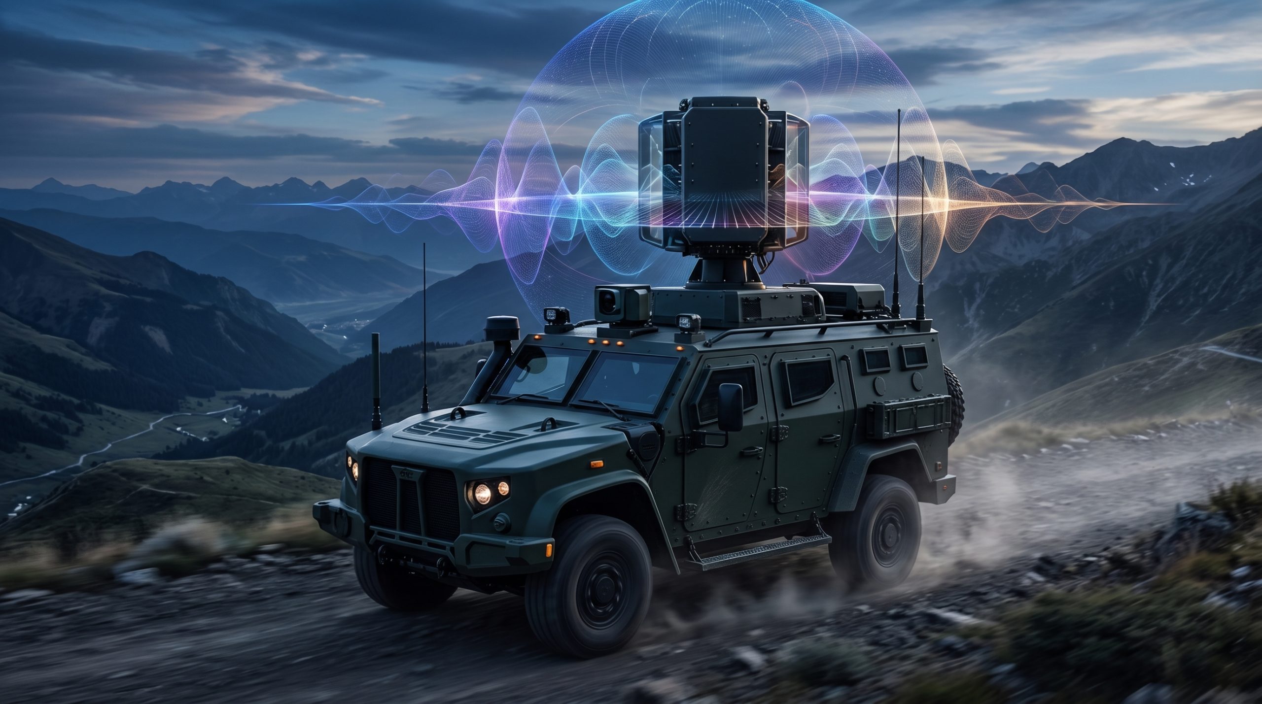
Build the mobile antenna range path around real hardware
For mobile RF coverage projects, CorelixRF can align omnidirectional antenna selection with UHF amplifier range, cabling, mounting, front-end packaging and validation evidence.
Engineering Decision and RFQ Checklist
This page is now treated as a primary RF engineering guide for antenna mounting, cable loss, pattern stability and range review. Use the checklist below to turn the article into a buyer-ready RFQ and factory review package.
| Decision Area | What to Confirm | Evidence to Request |
|---|---|---|
| Operating condition | Band, output power, duty cycle, waveform or sweep condition. | Rated operating table and test setup notes. |
| Interface | RF connector, load or antenna condition, control interface and power supply. | Interface drawing, control table and connector limits. |
| Reliability | Thermal path, protection behavior, enclosure airflow and environmental margin. | Thermal data, protection event notes and inspection records. |
| Acceptance | Gain, flatness, power, mismatch behavior, stability or repeatability limits. | FAT checklist, calibration state and final test curves. |
- RFQ checklist – convert requirements into buyer-ready fields.
- RF configurator – summarize band, power, interface and duty-cycle requirements.
- Delivery documentation – align test curves and FAT-style evidence.
- Case studies – compare how engineering issues become procurement decisions.
- Contact CorelixRF – send the requirement package for review.
Primary Topic Hub and RFQ Path
This primary guide now consolidates related RF engineering references. Use it for the current technical explanation, RFQ preparation, factory review and delivery documentation path.
- How to Maximize Range With Directional and Omnidirectional Antennas? – consolidated reference
The purpose is to reduce duplicate SEO pages while keeping buyers on one stronger engineering guide with clearer RFQ and documentation paths.
- RFQ checklist – prepare band, power, duty cycle, interface, cooling and acceptance inputs.
- RF configurator – turn project requirements into a first engineering brief.
- Delivery documentation – align test curves, inspection records and FAT-style evidence.
- Case studies – review how CorelixRF frames RF problems for buyer decisions.
- Contact engineering sales – submit the documented scope for review.
An omnidirectional antenna proves ideal for mobile units because it transmits signals equally across all horizontal planes, preventing connection drops during transit. Tactical teams frequently struggle with maintaining stable communication networks across rugged, unpredictable terrain. Every dropped packet jeopardizes mission safety and creates severe operational delays. Implementing a high-performance Omnidirectional Antenna built for continuous coverage guarantees unbroken links regardless of vehicle orientation. We design robust RF architectures securing critical data streams globally.
1. Why Choose an Omnidirectional Antenna?
Choosing an Omnidirectional Antenna guarantees seamless 360-degree signal reception during mobile operations without requiring manual adjustments. You demand reliable connections when navigating complex physical environments. This technology keeps your command vehicles constantly linked with forward operating elements.
Core Benefits for Mobile Fleets
Here is the deal: maintaining unbroken communication saves lives during high-stress tactical scenarios. You cannot afford dead zones when coordinating multiple moving assets simultaneously.
- Immediate network integration upon arrival
- Elimination of complex tracking mechanisms
- Consistent signal strength across diverse landscapes
Overcoming Deployment Delays?
Rapid movement requires gear that functions instantly upon power-up. You skip tedious calibration phases associated with directional setups. Plug-and-play efficiency accelerates overall mission timelines tremendously.
Key Technical Advantages
Modern hardware integrates robust materials capable of withstanding harsh physical vibrations. Your equipment must survive rough transit before transmitting any data.
Key Takeaway: Deploying this specific hardware drastically reduces setup times while guaranteeing continuous, reliable connectivity for dynamic vehicle fleets.
| Feature | Directional | Omnidirectional |
| Coverage Area | Focused | 360-Degree |
| Setup Speed | Slow | Instant |
| Mobility | Low | High |
This comparison clearly highlights superior adaptability when maintaining constant physical movement.
2. How Does an Omnidirectional Antenna Work?
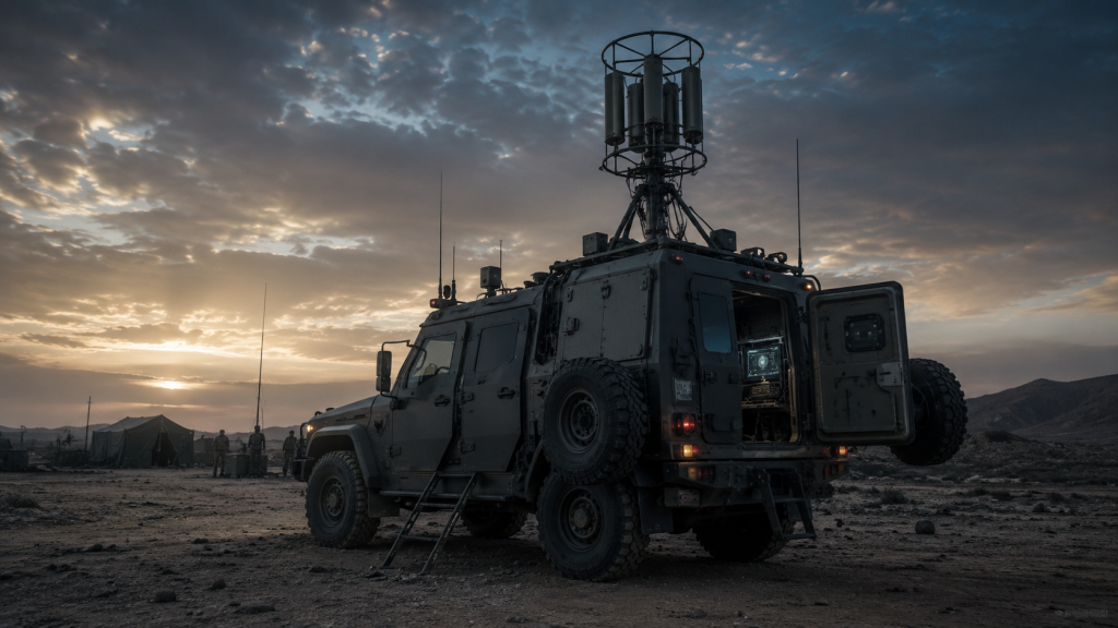
An Omnidirectional Antenna works by radiating radio frequency energy uniformly outward across a flat horizontal plane. You gain equal field strength regardless of which direction your vehicle faces. This geometric dispersion eliminates blind spots typically caused by sudden course changes.
Understanding Signal Dispersion
You might be wondering: how do these devices handle varied terrain elevations?
- Doughnut-shaped radiation patterns cover vast horizontal distances.
- Vertical beamwidth dictates how high or low signals travel.
- Lower gain options provide wider vertical angles for mountainous regions.
Managing Environmental Interference?
Physical obstacles like buildings reflect radio waves randomly. Your receiver captures these bounced signals through multipath propagation. Smart engineering guarantees these reflections reinforce rather than cancel your primary data link.
The Physics Behind Performance
Internal radiating elements use precise mathematical lengths matching specific operating frequencies. Proper tuning maximizes power transfer from your amplifier out into open space.
Key Takeaway: Understanding exact radiation patterns helps you select equipment perfectly matched for your specific geographical operating environments.
| Metric | Low Gain | High Gain |
| Vertical Spread | Wide | Narrow |
| Horizontal Range | Shorter | Longer |
| Best Terrain | Hilly | Flat |
Selecting appropriate gain values directly impacts overall network resilience across varying topography.
3. Where Does an Omnidirectional Antenna Excel?
An Omnidirectional Antenna excels in scenarios demanding constant communication between rapidly moving nodes spread across unpredictable locations. You benefit immensely from this design during emergency response operations or mobile border patrols. Constant realignment becomes impossible when target coordinates change every few seconds.
Tactical Field Operations
What is the real story? Static towers fail when situations remain highly fluid.
- First responders rely on uninterrupted voice channels.
- Convoy escorts maintain secure data meshes effortlessly.
- Unmanned ground vehicles receive continuous pilot commands.
Urban vs Rural Deployments?
City streets create deep concrete canyons blocking direct line-of-sight connections. Your signals bounce off structures, creating scattered but usable RF environments. Open rural fields allow waves straight paths, maximizing effective operational ranges.
System Integration Realities
Modern communication hubs consolidate multiple frequency bands into single physical masts. You save precious roof space on armored transport units.
Key Takeaway: These devices provide unmatched versatility across diverse operational theaters requiring rapid deployment without infrastructure reliance.
| Environment | Primary Challenge | System Benefit |
| Urban City | Concrete Blockage | Multipath Reception |
| Open Desert | Extreme Distances | High-Gain Horizon |
| Dense Forest | Signal Absorption | Lower Frequency Penetration |
Adapting hardware choices based on environmental factors secures maximum operational success rates.
4. Can an Omnidirectional Antenna Increase Range?
An Omnidirectional Antenna increases range by compressing vertical signal spread, thereby pushing more energy outward along horizontal axes. You achieve longer communication distances by selecting units with higher gain ratings. Excessive compression narrows your vertical coverage, potentially missing aircraft or valley locations.
Balancing Gain and Coverage
But here is the kicker: higher numbers do not always equal better performance.
- Increased gain flattens radiation patterns drastically.
- High-gain models excel on completely flat salt flats.
- Low-gain variants perform better traversing steep mountain passes.
Power Amplifier Synergy?
Adding raw wattage behind your broadcast significantly extends effective distance. You must confirm your hardware handles thermal loads generated by continuous high-power transmission. Properly matched components prevent dangerous system failures.
Overcoming Cable Loss
Long coaxial runs drain precious RF energy before reaching your mast. You must utilize thick, low-loss cables for connecting internal radios outside.
Key Takeaway: Maximizing reach requires carefully balancing physical gain characteristics against underlying transmitter power and cabling efficiency.
| Gain Rating | Vertical Beam | Ideal Usage |
| 3 dBi | Broad | Mountainous Terrain |
| 6 dBi | Medium | Mixed Landscapes |
| 9 dBi | Very Narrow | Flat Open Plains |
Choosing correct specifications prevents signal overshoots and guarantees reliable ground-level connectivity.
5. Why Pair an Omnidirectional Antenna with GaN?
Pairing an Omnidirectional Antenna with Gallium Nitride technology delivers unparalleled broadband power density within incredibly compact physical dimensions. You achieve military-grade output levels without overburdening vehicle electrical systems. This combination handles continuous wave transmission effortlessly under extreme thermal conditions.

The Gallium Nitride Advantage
Ready for the good part? Older silicon parts melt under modern tactical loads.
- GaN operates efficiently at extremely high temperatures.
- Wideband capabilities cover entire spectrums simultaneously.
- Reduced cooling requirements save massive amounts of space.
Maximizing RF Chain Efficiency?
Your transmitter requires absolute impedance matching throughout every component stage. Reflected power damages sensitive internal electronics instantly. Superior engineering minimizes VSWR, keeping your operations fully functional.
Future-Proofing Mobile Networks
Next-generation waveforms demand immense linearity from amplification stages. Distortion ruins digital packets, causing severe communication breakdowns.
Key Takeaway: Integrating cutting-edge amplification materials guarantees your mobile units deliver overwhelming signal dominance reliably.
| Technology | Efficiency | Thermal Tolerance |
| LDMOS Silicon | Moderate | Low |
| GaAs Base | Good | Moderate |
| GaN Core | Exceptional | Extremely High |
Transitioning toward modern semiconductor materials represents a massive leap in tactical operational endurance.
6. Does an Omnidirectional Antenna Stop Drones?
An Omnidirectional Antenna stops drones by radiating localized jamming signals, creating a protective bubble around sensitive mobile assets. You effectively sever rogue UAV command links from all approaching angles simultaneously. This immediate 360-degree suppression neutralizes swarms without requiring precise visual tracking.
Electronic Warfare Applications
This is where it gets interesting: reactive defenses outpace human operator speeds.
- Broad spectrum coverage jams multiple frequencies at once.
- Instant activation secures perimeters within milliseconds.
- Automated systems trigger responses based on radar cues.
Defeating Swarm Tactics?
Hostile forces utilize multiple inexpensive drones attacking from varied vectors simultaneously. Directional jammers simply cannot track thirty targets approaching from opposing compass points. A spherical defense perimeter easily disables overwhelming numerical advantages.
Integration with CorelixRF Hardware
Our systems provide seamless frequency hopping capabilities across wide spectrums. You maintain absolute control over local electromagnetic environments.
Key Takeaway: Spherical signal saturation remains the most reliable defense against coordinated multi-directional unmanned aerial vehicle attacks.
| Defense Method | Tracking Required | Swarm Capability |
| Directional Gun | Yes | Poor |
| Kinetic Net | Yes | Very Poor |
| 360-Degree RF | No | Excellent |
Deploying spherical RF suppression creates impenetrable invisible shields protecting high-value mobile targets effortlessly.
7. How to Mount an Omnidirectional Antenna?
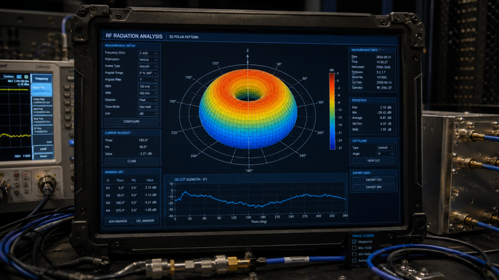
You mount an Omnidirectional Antenna at highest possible vehicle points, minimizing signal blockage from metal body panels. You must confirm a solid electrical ground plane connection for maximum radiation efficiency. Improper installation severely limits range and causes dangerous localized radiation hotspots.
Securing Mobile Hardware
Consider this: vibrations destroy poorly mounted electronics rapidly.
- Utilize heavy-duty magnetic or bolted NMO mounts.
- Apply thread-locking compounds on all metallic fasteners.
- Waterproof all coaxial connections using self-amalgamating tape.
Dealing with Ground Planes?
Many models require a flat metallic surface beneath them reflecting waves outward. Fiberglass roofs necessitate adding external metal plates for proper functionality. Without this reflective base, your signal pattern points uselessly toward the sky.
Avoiding Vehicle Interference
Lightbars, sirens, and other roof accessories distort radio waves unpredictably. You must maintain adequate physical spacing between emitting devices.
Key Takeaway: Rigorous installation practices directly dictate whether your expensive hardware performs properly during critical field operations.
| Mount Type | Durability | Ground Plane |
| Magnetic | Moderate | Built-in via roof |
| Through-Hole | Maximum | Excellent |
| Bracket | High | Requires external |
Selecting robust mounting solutions prevents catastrophic mechanical failures during off-road high-speed transit.
8. Are Omnidirectional Antenna Specs Reliable?
Omnidirectional Antenna specs prove reliable only when verified through rigorous military-grade laboratory testing like MIL-STD-810 protocols. You often encounter exaggerated marketing claims regarding gain or power handling from unverified suppliers. Actual field performance frequently falls short unless backed by comprehensive Engineering Truth.
Decoding Technical Datasheets
Think about it: paper specifications mean nothing during a firefight.
- Look for guaranteed maximum VSWR, not just typical values.
- Verify continuous power ratings versus peak burst claims.
- Demand true gain figures measured in an anechoic chamber.
The Danger of Counterfeits?
Cheap replicas use inferior internal metals causing severe signal degradation. These units literally melt internally when pushed with heavy amplifier loads. Your entire communication chain fails due to one weak link.
Insisting on Quality Control
Our 46-step protocol tests components far beyond standard limits. You receive hardware proven capable of surviving extreme thermal cycling.
Key Takeaway: Partnering with transparent manufacturers guaranteeing absolute technical accuracy protects your investments and operational readiness.
| Metric | Marketing Claim | Engineering Truth |
| Power Rating | 500W Peak | 150W Continuous |
| Gain Level | 10 dBi | 6 dBi True |
| VSWR | < 1.2 Typical | < 1.5 Maximum |
Demand verifiable testing data before trusting critical infrastructure to unproven commercial hardware components.
9. When to Upgrade an Omnidirectional Antenna?
You should upgrade an Omnidirectional Antenna when introducing newer, high-power amplifiers exceeding current hardware thermal dissipation limits. You must also replace units exhibiting physical degradation like cracked radomes or corroded connectors. Operating compromised equipment introduces severe network latency and drastically reduces overall range.
Identifying System Bottlenecks
Want to know a secret? Old masts destroy modern digital radios.
- High VSWR readings indicate internal element failure.
- Intermittent connection drops signal broken coaxial joints.
- Physical water ingress ruins tuning precision instantly.
Moving to Wider Bands?
Legacy systems often support single narrow frequency slices natively. Modern software-defined radios require broad spectrum compatibility for frequency hopping. Upgrading guarantees your hardware matches advanced digital processing capabilities.
Future-Proofing Investments
Expanding your operational scope requires scalable RF components. You save money long-term by purchasing wideband models initially.
Key Takeaway: Proactive hardware modernization prevents sudden catastrophic communication blackouts during vital active deployments.
| Condition | Symptom | Required Action |
| High VSWR | Radio Overheating | Immediate Replacement |
| Cracked Shell | Water Damage | Swap Unit |
| Narrow Band | Blocked Hopping | Upgrade to Wideband |
Regularly auditing your external hardware guarantees peak performance from expensive internal radio systems.
10. Which Omnidirectional Antenna Suits You?
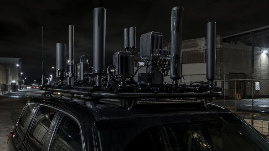
The Omnidirectional Antenna suiting you depends entirely upon specific operational frequency bands, required power thresholds, and geographic deployment terrain. You must clearly define your mission parameters before selecting hardware to guarantee complete system synergy. Matching components incorrectly wastes budget and limits tactical effectiveness.
Defining Operational Requirements
Here is the deal: custom problems require customized engineering solutions.
- Determine exact transmit and receive frequency ranges.
- Calculate maximum continuous RF power output levels.
- Assess typical geographic topography for gain selection.
Consulting RF Engineers?
Off-the-shelf products rarely fit complex military architectures perfectly. You benefit from direct collaboration with actual manufacturing experts. Dedicated professionals design solutions tailored specifically around your unique constraints.
Completing the RF Chain
A mast represents merely one piece of a larger puzzle. You need matched amplifiers, signal sources, and pristine cabling.
Key Takeaway: Taking a holistic system-level approach guarantees your mobile communication networks function flawlessly under pressure.
| Requirement | Suggested Feature | System Impact |
| Hilly Terrain | Low Gain (3dBi) | Better vertical reach |
| High Power | Heat-sink Base | Prevents melting |
| Broad Spectrum | Wideband Tuning | Supports hopping |
Collaborating with a dedicated manufacturing partner simplifies procurement and guarantees absolute technical compatibility.
Final Thoughts
You now understand why 360-degree coverage remains necessary for maintaining unbreakable connections across moving platforms. Deploying proper hardware eliminates dead zones, secures tactical networks, and protects mobile assets against electronic threats. CorelixRF engineers military-grade full-band RF chains designed specifically for extreme environments. Please contact us today to start your custom engineering project. We believe in delivering absolute Engineering Truth globally.
FAQ
Q1: Can I use one mast for multiple frequencies?
Yes, you can utilize wideband models designed specifically to cover broad spectrums simultaneously. This single-unit approach significantly reduces physical clutter atop your vehicle roof.
Q2: What is the best gain for mountain driving?
Lower gain units provide superior vertical signal spread required for steep terrain navigation. High gain models flatten your signal, shooting uselessly over deep valleys.
Q3: How do I know if my equipment is failing?
High VSWR readings directly on your radio interface usually indicate physical damage or internal water ingress. Immediate hardware replacement prevents catastrophic transmitter burnout.
Q4: Can I stop drones using this technology?
Yes, broadcasting high-power jamming signals through these specific devices creates a protective spherical shield. This localized suppression neutralizes multi-directional swarm attacks highly effectively.
Q5: What makes military-grade hardware different?
Military-grade units survive rigorous environmental testing including extreme thermal cycling and severe vibration stress. They consistently handle continuous high-power transmission without experiencing thermal degradation.
Turn this RF requirement into a quotable specification
Use this article as a starting point for a buildable RF specification. Before quoting, CorelixRF normally checks frequency range, output power, gain flatness, duty cycle, load mismatch, thermal path, control interface, enclosure limits and acceptance data.
- custom RF antenna support – match antenna pattern, connector, radome and mounting limits to the RF chain
- directional antenna options – compare directional antenna choices for link budget and installation constraints
- RF configurator – turn frequency, power, thermal and interface requirements into a first configuration brief
- RFQ checklist – send the data buyers usually forget, including band, power, duty cycle, interface and test standard
- delivery documentation – check what documents can support incoming inspection, FAT review and long-term maintenance
- case studies – review similar engineering paths before sending an RFQ
- engineering contact – send the application notes, block diagram or target specification to engineering sales
For a faster review, send operating band, power target, modulation or waveform, antenna/load condition, cooling limit, mechanical envelope and target test standard through the RFQ or contact path.