
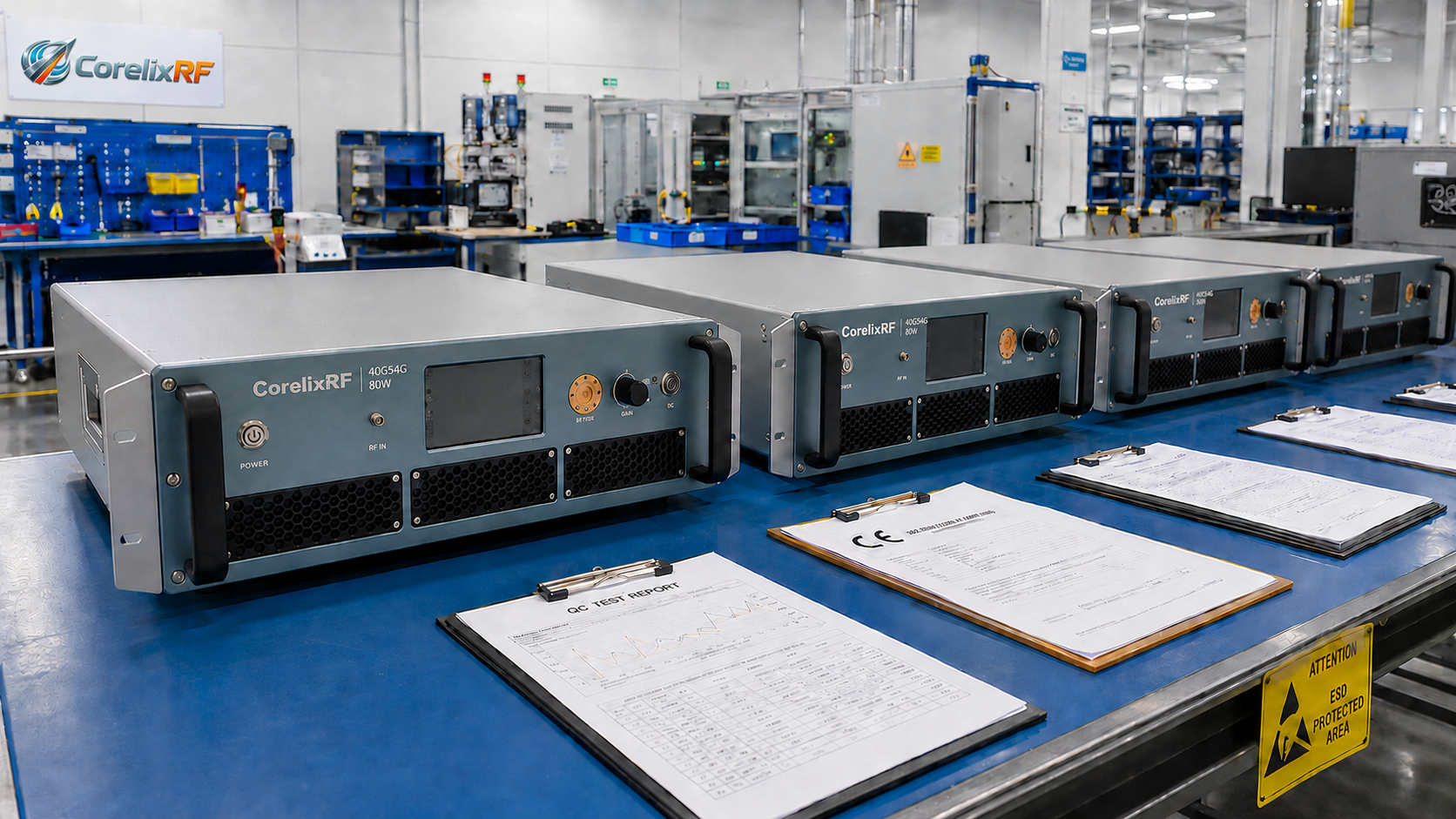
Missing deadlines on custom RF power amplifier procurements forces system integrators into severe financial penalties. Project managers frequently face misaligned expectations regarding thermal performance alongside impedance matching during final stages. Adopting strict engineering-driven milestones prevents schedule overruns. CorelixRF brings 30 years of manufacturing high-power modules. We offer transparent schedules based strictly upon factory acceptance testing. Managing complex supply chains demands absolute technical clarity from day one. Vendors must demonstrate measured results rather than theoretical promises. Here is the deal, relying solely on paper specifications causes integration failures later. We outline a rigid milestone protocol designed for project managers requiring accurate timelines alongside physical hardware verification. Establishing clear communication protocols early prevents catastrophic misunderstandings during later assembly phases. System builders need reliable partners supplying honest production updates continuously. We prioritize objective engineering truths over empty marketing promises.
1. What Are the Core Stages in RF Amplifier Delivery Management?
● Design Freeze Protocol
● First Article Inspection
● Volume Production
Setting clear boundaries during hardware development prevents scope creep. What is the real story? Changing parameters after initial approval forces a complete redesign regarding matching networks. A firm design freeze guarantees engineers focus entirely upon layout realization. First article inspection validates physical parameters against theoretical simulations. Technicians measure small-signal gain flatness alongside harmonic suppression strictly at this stage. Volume fabrication begins only after passing initial hardware scrutiny. Managing 400 manufacturing personnel requires disciplined gating between these phases. CorelixRF enforces rigid stage-gate reviews dictating zero deviation from agreed mechanical constraints. Setting milestones early keeps procurement teams aligned alongside engineering realities. Project managers avoid penalties by adhering strictly toward predetermined production schedules. Evaluating vendor capability requires examining historic adherence toward promised milestone delivery dates. Late deliveries often stem from poor component inventory planning during early procurement cycles. Securing long lead time components upfront protects downstream assembly schedules significantly. Table one details standard phase durations for typical solid-state power amplifier builds.
Phase Durations
| Phase | Activity | Output | Duration |
| Phase 1 | Requirements Review | Locked Specifications | 1 Week |
| Phase 2 | Design Freeze | Mechanical Drawings | 2 Weeks |
| Phase 3 | First Article | Prototype Hardware | 4 Weeks |
| Phase 4 | FAT Validation | Test Reports | 1 Week |
| Phase 5 | Volume Build | Final Units | Variable |
2. How Do Physical RF Risks Threaten Delivery Management Schedules?
● Impedance Mismatch
● Gain Drift
● Thermal Runaway
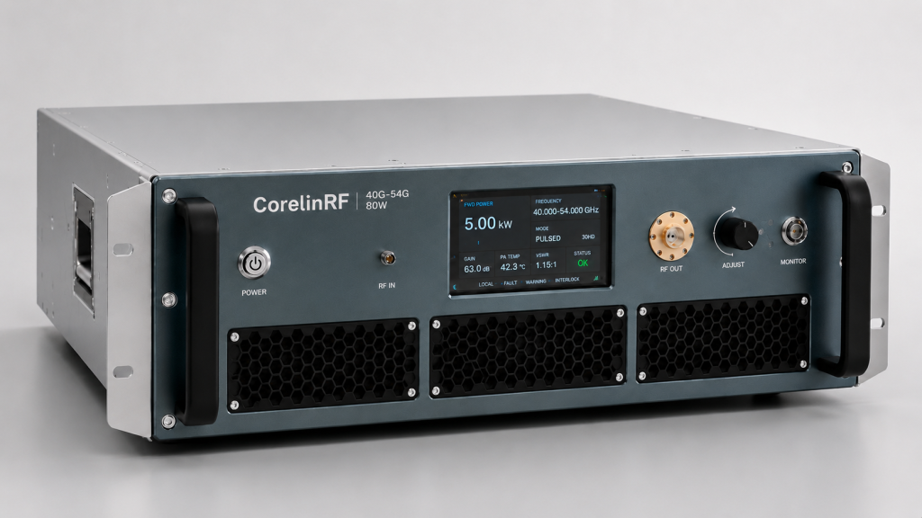
Failing anticipating physical limitations causes late-stage timeline collapses. You might be wondering, why do prototypes often fail initial testing? High-frequency layouts suffer from parasitic capacitance altering predicted performance. Impedance mismatch at millimeter-wave frequencies reflects power back into active components causing immediate destruction. Engineers must monitor gain drift across specified operating temperatures diligently. Thermal runaway remains a constant threat inside compact high-power modules whenever cooling methods prove inadequate. Incorporating real-time temperature diagnostics mitigates sudden catastrophic failures during continuous operation. We mandate exhaustive thermal cycling prior toward final sign-off. Hardware anomalies discovered during final integration create massive shipment delays. Addressing physical constraints upfront secures predictable manufacturing outcomes. Selecting premium GaN transistors provides wider safe operating areas compared against older LDMOS technologies. Implementing redundant alarm logic prevents cascading catastrophic failures across multiple amplifier stages. Solid mechanical grounding prevents unwanted chassis resonances interfering against precise microwave signal paths. Table two illustrates common hardware risks alongside specific mitigation tactics.
Hardware Risk Mitigation
| Risk Factor | Physical Mechanism | Mitigation Strategy |
| Thermal Runaway | Inadequate heat dissipation | Forced air cooling analysis |
| Power Reflection | Severe VSWR conditions | Isolator integration |
| Gain Degradation | Temperature variations | Compensation circuitry |
| Component Failure | Over-voltage conditions | Built-in alarm protection |
3. Why Does Factory Acceptance Testing Control Delivery Management?
● Parameter Verification
● Environmental Stress
● Interface Validation
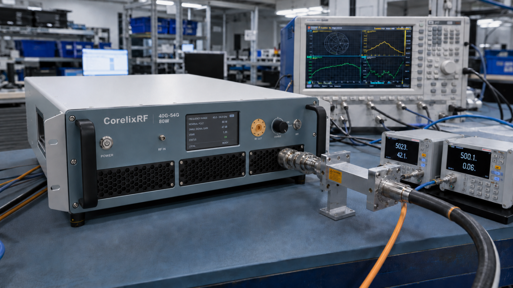
Verifying datasheet claims through physical measurement defines Factory Acceptance Testing. This is where things get interesting. CorelixRF utilizes our CRF-PA-40000M54000M-80W platform as a baseline for millimeter-wave validation. This specific unit operates from 40 GHz up through 54 GHz. The rated output power guarantees 80 W of solid-state RF energy. Engineers verify a 50 dB minimum small-signal gain during standard production test configurations. Hardware includes a 1.85mm-F front panel input connector alongside WR19 waveguide outputs. We subject this GaN design toward rigorous diagnostics checking temperature and current parameters. Passing these rigorous laboratory evaluations remains mandatory before releasing any shipment. Skipping physical verification steps guarantees field failures later down the line. Utilizing calibrated vector network analyzers provides extreme accuracy measuring phase variations across multi-octave bandwidths. Employing directional couplers allows precise forward power measurements without interrupting main transmission lines. Table three details measured parameters required for factory release.
FAT Parameters
| Parameter | Specification | Verification Method |
| Frequency Range | 40 – 54 GHz | Network Analyzer |
| Output Power | 80 W | Power Meter |
| Small-Signal Gain | 50 dB min | Network Analyzer |
| Form Factor | 19-inch 5U | Physical Measurement |
| Cooling | Forced air cooling | Thermal Chamber |
4. How Do Mechanical Constraints Dictate Delivery Management?
● Form Factor Planning
● Connector Selection
● Power Supply Integration
Physical dimensions directly limit electrical layout capabilities. Ready for the good part? Knowing spatial limits early prevents costly late-stage mechanical overhauls. The standard 19-inch 5U configuration provides adequate volume for forced-air cooling systems. Integrating an AC 220 V power supply requires careful isolation from sensitive RF routing. Control interfaces utilizing RS485 alongside LAN protocols need secure rear-panel access. Project managers must secure final mechanical drawings during initial project review phases. Failing securing dimension layouts delays chassis fabrication by weeks. Mechanical teams cannot machine custom heatsinks without frozen dimension requirements. Aligning structural engineering timelines alongside RF layout schedules guarantees parallel progress. Incorporating heavy duty lifting handles guarantees safe installation procedures inside tight server racks. Defining cable bend radii limits early prevents unwanted stress fracturing near delicate coaxial interfaces. Table four lists mechanical integration checkpoints necessary before moving forward.
Mechanical Checkpoints
| Integration Point | Requirement | Verification |
| Dimensions | 19-inch 5U form factor | Drawing Sign-off |
| Input Connector | 1.85mm-F front panel | Visual Inspection |
| Output Connector | WR19 waveguide | Fit Check |
| Control Port | RS485 and LAN | Protocol Test |
| Input Supply | AC 220 V | Load Test |
5. What Actions Guarantee Smooth Delivery Management at CorelixRF?
● Documentation Supply
● Communication Cadence
● Final Handover
Establishing transparent data exchange pipelines guarantees project alignment. Here is another fact, system integrators require credible test data rapidly for internal reviews. CorelixRF provides project-based regulatory documentation supporting CE alongside RoHS compliance where applicable. Supplying final mechanical drawings alongside test data happens upon request. We build custom test reports reflecting your exact waveform type alongside duty cycle requirements. Active communication regarding VSWR protection and alarm functions builds trust before shipment. Providing detailed factory acceptance records proves physical hardware matches theoretical claims. Procurement teams gain absolute confidence reviewing unedited laboratory measurement sheets. Supplying photographic evidence showing internal layout neatness demonstrates extreme manufacturing discipline. Offering dedicated technical support channels resolves integration queries rapidly post deployment. System builders appreciate receiving detailed user manuals defining every RS485 register address clearly. Table five outlines specific documentation packages provided upon project completion. Request a technical review or distributor kit today.
Handover Documentation
| Document Type | Purpose | Availability |
| Test Report | Verify RF parameters | Post-FAT |
| Mechanical Drawing | Installation reference | Project Review |
| Control Protocol | System integration | On Request |
| Compliance | CE / RoHS | Where applicable |
Setting rigid milestones controls custom RF amplifier manufacturing schedules. Enforcing strict design freezes prevents late-stage engineering delays. Validating physical hardware through Factory Acceptance Testing guarantees system integrators receive reliable equipment. Project managers must demand measured data regarding VSWR protection alongside thermal stability. Overlooking mechanical form factors early causes severe rack integration headaches downstream. Mandating exhaustive temperature cycling proves long-term device reliability under harsh operational conditions. Securing complete documentation packages streamlines final system certification processes globally. Partnering alongside experienced manufacturers reduces overall technical risk significantly. Request an engineering review or distributor kit today.
FAQ Section
Q1: What defines a design freeze in RF hardware manufacturing?
A design freeze strictly prohibits further schematic or mechanical modifications. Engineers lock down precise layout dimensions. Manufacturing proceeds based entirely upon these finalized parameters. Preventing scope creep guarantees production lines remain highly efficient. Any late parameter changes require starting the entire validation process completely over.
Q2: How does VSWR protection prevent amplifier module destruction?
Reflected power causes extreme heat buildup rapidly. Built-in VSWR protection detects severe impedance mismatch conditions directly. The control system triggers an alarm and reduces drive levels automatically. Active monitoring prevents expensive GaN transistors from experiencing immediate catastrophic burnout. This logic saves thousands in replacement costs.
Q3: What data should project managers provide for an accurate quotation?
Buyers must provide target frequency ranges alongside output power levels. Waveform types and mechanical constraints remain necessary for accurate engineering reviews. Detailed environmental requirements dictate correct chassis selection. Clearly defining continuous wave versus pulsed operation dictates internal power supply sizing. Defining exact interface protocols guarantees seamless software integration later.
Q4: Why is first article inspection considered critical?
This stage proves physical manufacturability absolutely. Testing real hardware validates theoretical simulation models perfectly. Approval guarantees volume production yields meet initial engineering expectations. Identifying layout errors early prevents producing hundreds of flawed production units. Procurement teams receive physical proof verifying vendor manufacturing capabilities genuinely.
Q5: What cooling mechanisms support 80 W millimeter-wave amplifiers?
High-power modules require aggressive thermal management constantly. A standard 19-inch 5U chassis utilizes forced air cooling. This technique maintains safe operating temperatures across all active GaN components. Properly sized aluminum heatsinks distribute concentrated thermal loads evenly across larger surface areas. Powerful internal fans pull ambient air across delicate matching networks continuously.
Prevent schedule slips with RFQ-ready inputs
Most RF amplifier schedule delays come from missing interface, cooling, power, control or acceptance details. Use a complete RFQ package so engineering can quote from facts instead of assumptions.
Recommended next step: send the operating band, required output power, duty cycle, load condition, control interface, cooling limit, protection behavior and required FAT documents. CorelixRF can map this RF amplifier project schedule control requirement to a standard platform, a controlled modification or a custom RF build.