
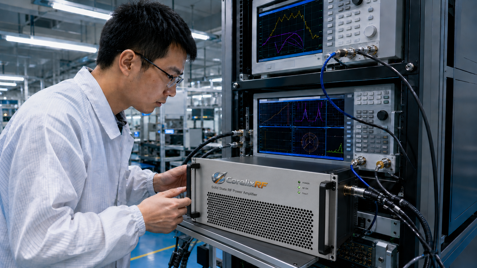
R&D engineers frequently encounter massive risks during RF system integration when custom power amplifiers fail laboratory testing. Hardware might miss target field strength requirements completely. Systems sometimes suffer thermal shutdown during continuous operation. Missing these performance targets ruins test schedules and escalates budget overruns. Here is the deal: mitigating these failures demands precise knowledge regarding hardware constraints. This technical selection guide outlines six core parameters dictating cost and delivery schedules. Aligning specifications with established physical mechanisms guarantees reliable performance. CorelixRF builds equipment based on strict laboratory data rather than marketing claims. We engineer solutions grounded purely on physical realities.
1. Frequency Band and Output Power Specifications
Broadband operation inherently conflicts with high-efficiency power delivery. Requesting multi-octave coverage like a 6 GHz through 18 GHz frequency range with 500 W output power massively increases RF matching network complexity. Generating 500 W across such wide spectrums mandates state-of-the-art GaN solid-state technology. You might be wondering: how does this impact your project timeline? Narrowband amplifiers utilize existing reference designs requiring minimal tuning. Conversely, wideband systems demand rigorous electromagnetic simulation alongside extended bench tuning. Technicians must maintain 57 dB minimum small-signal gain while keeping flatness within a -6 dB through +6 dB window. Specifying unnecessarily wide frequency bands forces manufacturers out from standard production test configurations. This choice increases component costs and adds weeks of laboratory tuning. Physical parasitic capacitance inside GaN dies degrades performance above 12 GHz. Engineers counter this physical mechanism using complex Wilkinson combiners. Combiner insertion loss rises at higher frequencies. Overcoming combiner loss requires driver stages pushing higher current. Higher current demands heavily impact final material budgets.
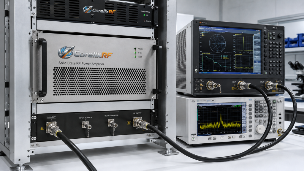
| Parameter | Standard Value | Impact on Cost and Lead Time |
| Frequency Range | 6,000 – 18,000 MHz | Wideband tuning extends laboratory testing time |
| Output Power | 500 W | High power requires specialized combining networks |
| Small-Signal Gain | 57 dB min | High gain dictates multi-stage cascade designs |
| Gain Flatness | -6 dB through +6 dB | Strict flatness requires complex equalization circuits |
2. Linearity and Waveform Constraints
RF amplifiers behave differently under Continuous Wave (CW) versus pulsed operation. Hardware destined for communication systems or RF interference testing necessitates strict linearity. High linearity demands active devices operating backed-off from their P1dB compression point. What is the real story? Complex modulation schemes cause severe AM/AM and AM/PM distortion. Managing this distortion involves precise GaN biasing circuits. Submitting RFQs without explicitly defining waveform types creates massive delays. Ambiguous requirements inevitably lead toward redesign phases. Engineers must source new components validated against strict spurious emission limits of -60 dBc. Providing accurate peak-to-average power ratio data allows engineering teams fast component selection. Amplifiers pushing CW signals generate massive continuous heat loads. Pulsed signals create thermal cycling stress on semiconductor die attachments. Micro-cracking occurs unless engineers design specific matching networks managing peak transient currents. Understanding base physical mechanisms prevents catastrophic hardware failures during final site acceptance testing.
| Waveform Type | Linearity Requirement | Engineering Impact |
| Continuous Wave | Standard | Baseline thermal and power supply design |
| Pulsed | Moderate | Requires transient response analysis |
| Complex Modulation | Strict | Demands pre-distortion and severe power back-off |
| High PAPR Signal | Extreme | Necessitates oversized GaN devices |
3. Thermal Management and Continuous Operation
Heat acts as the primary enemy destroying solid-state RF power amplifiers. Delivering continuous high-power output generates massive thermal dissipation loads. GaN transistors experience thermal runaway without adequate cooling mechanisms. Systems operating up through 18 GHz at 500 W require robust air cooling for survival. Ready for the good part? Proper thermal design guarantees continuous operation and field strength stability. CorelixRF integrates real-time temperature monitoring and over-temperature protection directly into every system architecture. Standard models operate reliably between 0 and +50 °C. Requesting operation inside extreme environments beyond this range forces complete mechanical redesigns. Custom heatsink extrusion and airflow simulation represent time-intensive processes. Specifying standard cooling configurations drastically reduces engineering overhead. Base physics dictate thermal impedance from junction through case boundaries. Air cooling a 500 W RF amplifier running low efficiency means dissipating immense heat. AC 380 V ±10% power supplies must provide massive current. Three-phase power reduces voltage ripple. Industrial fans must push hundreds of cubic feet per minute.
| Cooling Parameter | CRF-PA Specification | Hardware Design Impact |
| Cooling Method | Air cooling | Standard fan selection limits custom machining |
| Operating Temperature | 0 through +50 °C | Defines thermal interface material limits |
| Built-in Protection | Over-temperature | Prevents catastrophic transistor failure |
| Power Supply | AC 380 V ±10%, 50/60 Hz | Requires massive internal heat dissipation |
4. Mechanical Form Factor and RF Connectors
Physical dimensions and chosen RF interfaces heavily influence manufacturing schedules. High-frequency applications require specific connector types. Proper selection prevents severe impedance mismatch and high VSWR issues. A 500 W system operating at 18 GHz utilizes an N-Female connector for RF input. It requires a WRD650 Waveguide for RF output. This is where it gets interesting: Mechanical form factors often remain TBD during early project phases. Delaying mechanical constraints forces manufacturers into halting chassis production. Every custom dimension demands new CNC programming and surface treatment. Engineers should accept standard rack-mount chassis designs whenever possible. Project-specific mechanical configurations incur high non-recurring engineering fees. Standard coaxial connectors handle limited CW power before center pins overheat. WRD650 double-ridged waveguides cover wide frequency bands safely. Waveguides handle kilowatts of power exhibiting low insertion loss. Specifying wrong connectors causes dielectric breakdown under full power loads.
| Interface Point | Specified Standard | Manufacturing Constraint |
| RF Input Connector | N-Female | Limits input power handling below 0 dBm |
| RF Output Connector | WRD650 Waveguide | Prevents dielectric breakdown at 500 W |
| Mechanical Form Factor | TBD | Custom dimensions halt CNC production |
| Input Impedance | 50 Ω (1.5:1 VSWR typ.) | Requires precise connector machining tolerances |
5. Built-In Diagnostics and Control Interfaces
Modern aerospace control systems require sophisticated monitoring capabilities. Standard units include alarm and fault protection functions like over-drive protection. Built-in diagnostics protect hardware against antenna mismatch via VSWR protection. The bottom line: Integrating basic control interfaces like RS485 or LAN rarely delays production. Project-specific customization introduces heavy software development time. Requests for optional forward/reverse power monitoring or GPIB programmable control interfaces require rigorous debugging. Custom software validation must finish before supplying final test data for project review. Minimizing custom software requests accelerates delivery. Utilizing standard command sets keeps your budget intact. RS485 provides robust connectivity across noisy industrial environments. Ethernet connections allow remote firmware updates. Fast VSWR protection needs microsecond response times. Hardware comparators achieve this speed much better than software polling loops. Engineers relying on standard protocols avoid schedule overruns.
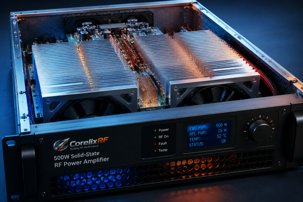
| Diagnostic Feature | Availability | Software Development Impact |
| Real-time temperature | Standard | Pre-programmed into base firmware |
| VSWR protection | Standard | Hardwired into RF control loop |
| LAN remote control | Optional | Requires custom network protocol integration |
| GPIB programmable control | Optional | Demands extensive custom software debugging |
6. Quality Compliance and Environmental Testing
Regulatory compliance heavily influences final delivery schedules. Equipment manufactured under an ISO 9001 quality management system requires strict documentation. High-power RF systems destined for global markets often need RoHS-compliant materials. Here is the kicker: Generating project-based regulatory documentation adds administrative delays. Custom compliance testing requires third-party laboratory time. Standard production test configurations undergo established burn-in procedures. Demanding unique environmental shock or vibration testing forces hardware out of standard workflows. Aligning your requirements with existing factory acceptance protocols saves money. Discussing destination market requirements early prevents last-minute shipping blocks. Factory acceptance testing verifies parameters like noise floors sitting at -25 dBm/MHz. Verification requires expensive vector network analyzers and spectrum analyzers. Custom test setups demand entirely new calibration routines. Using standardized factory protocols cuts testing time by days.
7. Recommended RFQ Submission Protocol
Poorly defined RFQs cause extended lead times. Manufacturers require precise parameters for generating accurate technical proposals. Vague requests trigger multiple rounds of clarification. This stalls the entire engineering review process. It all comes down to this: Your initial inquiry must be thorough. You must explicitly provide target frequency range, output power, waveform type, duty cycle, and control interfaces. Do not forget mechanical constraints and environmental requirements. Front-loading this engineering data allows CorelixRF rapid requirement matching against existing GaN SSPA platforms. We can then select appropriate test configurations providing realistic delivery schedules. Engineering teams immediately identify missing technical links. Specifying CW or pulse operation prevents incorrect transistor selection. Providing clear mechanical constraints allows immediate CNC machining scheduling. Thorough RFQs eliminate hidden non-recurring engineering costs entirely.
8. Final Engineering Review
Securing reliable RF power amplifiers requires balancing technical specifications against budget constraints. Frequency bandwidth, linearity, thermal management, mechanical design, and software integration drive project costs. Defining these parameters upfront guarantees successful system integration. CorelixRF delivers high-power equipment built upon verified physical data. Submit your complete RFQ today. Book a 48-hour engineering review with our technical team.
FAQ
Q1: What is the standard operating temperature range for the 500 W amplifier? Standard operating temperature ranges sit between 0 and +50 °C.
Q2: How does CorelixRF protect the amplifier from antenna mismatch? Systems feature built-in VSWR protection and alarm functions safeguarding against high reflected power.
Q3: What RF connectors are used for the 6-18 GHz 500 W model? Standard configurations use an N-Female connector for RF input and a WRD650 Waveguide for RF output.
Q4: What control interfaces are available for remote monitoring? Amplifiers support RS485 and LAN control interfaces alongside optional GPIB programmable control available upon request.
Q5: What information is required for a complete technical review? You must provide target frequency range, output power, waveform type, CW or pulse operation, duty cycle, control interface, mechanical constraints, and environmental requirements.
Separate custom needs from standard-platform options
For custom RF power amplifiers, clarify which requirements are fixed and which can follow a standard platform. This helps CorelixRF choose between a catalog-like build, controlled modification or full custom engineering path.
Recommended next step: send the operating band, required output power, duty cycle, load condition, control interface, cooling limit, protection behavior and required FAT documents. CorelixRF can map this custom RF power amplifier project delay prevention requirement to a standard platform, a controlled modification or a custom RF build.
Custom RF Amplifier Quoting Path
To reduce lead-time risk, map the article checklist to custom RF amplifier engineering, compare available RF power amplifier platforms, and define the RF front-end interface before RFQ release.