

Integrators face severe risks treating RF modules like simple commodities. A mismatched load causes instant thermal runaway. Thirty seconds of high reflection ruins expensive equipment. A reliable method exists for matching system requirements accurately. Here is the deal. CorelixRF builds engineered platforms, rather than stocking fragile commercial items.
Standard Platform and Rapid Customization: Defining Reusable Foundations
System builders frequently misunderstand standard specifications. They assume standard means ready for immediate field deployment. Such assumptions cause field strength compliance failures during final acceptance tests. Every radar or communication setup demands specific phase linearity along with precise gain flatness. We provide an engineering base designed for rapid adaptation. You might be wondering. How does this differ from commercial off-the-shelf inventory? An engineered foundation incorporates pre-validated physical mechanisms. It absorbs minor impedance mismatch without catastrophic failure. RF system integration requires strict verification procedures before field deployment. Our manufacturing process guarantees baseline performance metrics across all production units. We reject marketing fluff, focusing entirely upon laboratory-verified data points.
Platform Parameters
| Feature | Description |
| Architecture | Engineered Foundation |
| Verification | Laboratory Tested |
| Adaptation | Rapid Customization |
| Goal | Field Compliance |
Platform Value Through Advanced GaN Architecture
Our model CRF-PA-8000M12000M-100W serves as a prime example of reusable engineering. This specific GaN pulsed SSPA platform operates across 8 GHz up through 12 GHz. It delivers 100 W rated output power. Built upon advanced GaN technology, this unit supplies reliable RF power performance. What is the real story? It caters heavily toward test and measurement instrumentation, plus RF interference system-level testing. Aerospace control systems also benefit greatly from this robust design architecture. We maintain strict hardware parameters, achieving ±3.5 dB maximum gain flatness. Spurious emissions stay strictly bounded at -60 dBc maximum. Harmonics never exceed -20 dBc under standard test configurations.
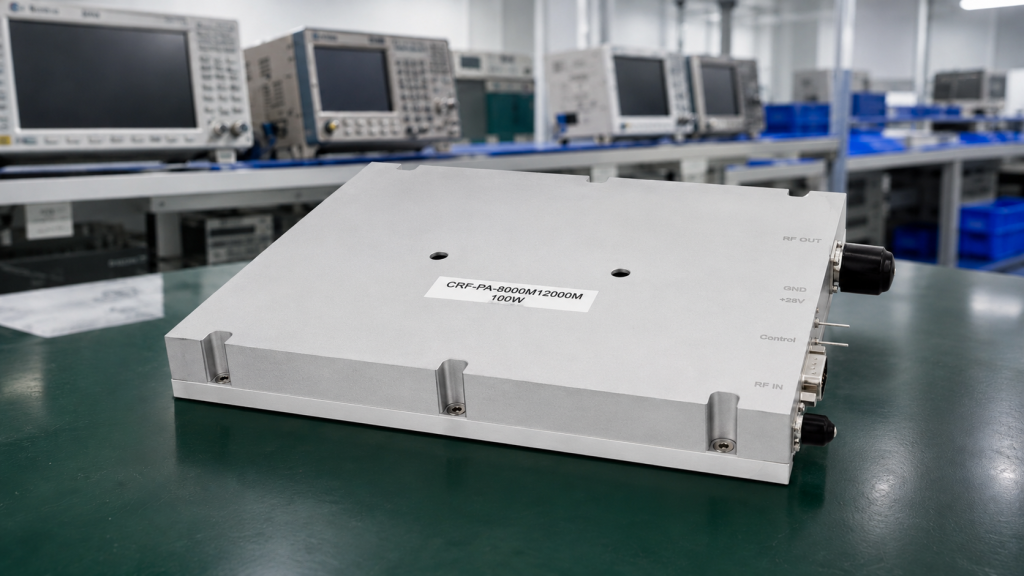
Key Electrical Specifications
| Parameter | Minimum | Maximum | Units |
| Frequency Range | 8 | 12 | GHz |
| Rated Output Power | 100 | – | W |
| Gain Flatness | – | ±3.5 | dB |
| Harmonics | – | -20 | dBc |
Rapid Customization Boundaries Defined By Physics
Customization must respect absolute physical limits. Pulse parameters remain strictly bound by thermal dissipation laws. For instance, our platform supports a pulse width between 500 ns up through 50 us. Maximum duty cycle caps at 10 percent. But here is the kicker Pushing beyond these boundaries guarantees gain drift. We provide minimum 52 dB small-signal gain. Input power must not exceed 0 dBm. Customization requests undergo rigorous engineering reviews matching proposed modifications against immutable physical mechanisms. Forward power monitoring, input detection, plus GPIB control interfaces can undergo review according to project requirements. Our technical team verifies every single operational parameter systematically.
Pulse and Gain Capabilities
| Characteristic | Value |
| Pulse Width | 500 ns up through 50 us |
| Duty Cycle | 0 up through 10% |
| Small-Signal Gain | 52 dB min. |
| Input Power Max | 0 dBm |
Continuous Operation Under Extreme Field Conditions
Continuous operation demands rigorous thermal management. An external heat sink remains strictly required. Mechanical form factor measures precisely 255 x 245 x 80 mm. Environmental operating temperature limits span from 0 up through +50 °C. This is where it gets interesting… Connectors feature SMA-F for input alongside N-F for output. A robust CAN control interface manages system communication. Input impedance maintains 50 Ω alongside a 2:1 VSWR tolerance. DC power supply operates safely at 28 V. Manufacturing occurs under strict ISO 9001 quality management system guidelines. Project-based regulatory documentation support remains available upon request.

Mechanical and Interface Details
| Interface | Specification |
| Dimensions | 255 x 245 x 80 mm |
| Operating Temp | 0 up through +50 °C |
| RF Input | SMA-F |
| RF Output | N-F |
Solving After-Sales Puzzles With Real-Time Diagnostics
After-sales support requires hard data, rather than guesswork. Our platforms integrate real-time temperature alongside current monitoring standard. We include comprehensive alarm and fault protection functions. These systems feature over-temperature, over-drive, plus over-voltage safeguards. Ready for the good part? We also incorporate VSWR protection alongside alarm capabilities. Forward and reverse power monitoring remains available as an optional customization. Engineering truth dictates transparent telemetry data sharing. Equipment longevity depends entirely upon proactive fault detection mechanisms. Our diagnostic architecture removes ambiguity during field troubleshooting scenarios. System integrators gain complete visibility over module health status.
Built-In Protection Matrix
| Protection Type | Status |
| Over-temperature | Standard |
| Over-drive | Standard |
| Over-voltage | Standard |
| VSWR Alarm | Standard |
System integration requires objective technical facts. A solid engineering base prevents costly field failures. For quotation or technical review, please provide target frequency range, output power, waveform type, duty cycle, mechanical constraints, plus environmental requirements. Submit your RFQ today. Schedule a 48-hour engineering review with our CorelixRF technical team.
FAQ
Q1: What is a standard platform in RF engineering?
A standard platform functions as a pre-validated engineering base featuring defined physical boundaries, rather than a finalized commercial product ready for immediate end-user deployment.
Q2: How does customization affect field strength compliance?
Customization modifies baseline parameters, demanding strict re-verification of linearity, gain drift, plus VSWR matching against specific integration environment requirements.
Q3: What are the thermal requirements for continuous operation?
Continuous operation mandates an external heat sink, maintaining operating temperatures between 0 and +50 °C to prevent thermal runaway and subsequent module failure.
Q4: How does built-in protection minimize after-sales issues?
Integrated diagnostics monitor real-time temperature and current, triggering alarms for over-voltage or VSWR mismatch before catastrophic hardware damage occurs.
Q5: What information is needed for a technical review?
Engineering teams require target frequency range, output power, waveform type, duty cycle, control interface, mechanical constraints, plus environmental requirements.
Turn the standard platform into a controlled customization plan
If your project needs a modified connector, control port, cooling path, enclosure or frequency window, start from the standard platform and define the delta clearly. This helps keep the discussion around lead time, interface risk, acceptance testing and documents instead of vague custom promises.
Recommended next step: send the target band, output power, duty cycle, load condition, control interface, cooling limit and required FAT documents. CorelixRF can map this RF amplifier standard platform customization requirement to a standard platform or a controlled customization path.