
Procurement and R&D teams advancing high-reliability RF system projects often face a core engineering schedule conflict: fully custom RF power amplifier development cycles are extremely long, delaying the entire system project; whereas directly procuring compromised commercial-off-the-shelf (COTS) models often leads to interface mismatches, control protocol incompatibilities, or thermal design flaws during system integration, ultimately causing factory acceptance test (FAT) failures.
The effective path to mitigate this engineering risk and significantly shorten lead times is adopting an RF Amplifier Standard Platform architecture. This article bypasses redundant marketing packaging to analyze the engineering essence of the platform architecture from the perspective of underlying physical mechanisms and reliability acceptance, demonstrating how it provides procurement decision-makers with credible delivery evidence and exceptionally fast response capabilities.
The Customization Trap and the Physical Limitations of COTS Models
When evaluating RF amplifiers, the RF system is not a simple input-output black box. When system integrators attempt to force poorly matched catalog models into specific enclosure dimensions or thermal environments, thermal management failures often occur due to altered heat dissipation paths or increased thermal impedance. For example, excessive contact thermal resistance can cause thermal grease to experience a “pump-out” effect during long-term operation, leading to severe gain drift and ultimately causing irreversible thermal damage to the core amplifier components.
Furthermore, the antenna or load end in actual application environments often cannot maintain an ideal 50-ohm impedance. If an impedance mismatch occurs, high-energy reflected power directly threatens the amplifier’s final-stage transistors. If conventional models lack highly robust Voltage Standing Wave Ratio (VSWR) protection mechanisms, severe mismatches can easily destroy the module. While purely custom development can resolve these issues at the physical layer, the 12 to 16 weeks required for RF chain reconstruction, thermal simulation verification, and reliability prototyping represent an unacceptable cost for market demands requiring rapid response.
What is an RF Amplifier Standard Platform?
An RF amplifier standard platform is not a compromise in performance, but a mature, verified “engineering modularity” strategy. CorelixRF’s standard platform refers to retaining the flexible configuration of external communication interfaces, monitoring and control logic, and mechanical enclosure dimensions, all built upon a baseline of underlying RF microwave chains, bias network designs, and extreme thermal management that have undergone comprehensive and rigorous continuous fatigue verification in the laboratory.
This architecture transforms the traditional “scratch-build” approach into “engineering reconstruction based on a known high-reliability baseline.” Taking CorelixRF’s wideband solid-state power amplifier (SSPA) architecture based on GaN technology as an example, the underlying platform has completely resolved wideband impedance matching across multi-octave bands and maintained linearity under high-power output conditions. This ensures that system designers do not have to assume the risk of core RF performance failure again.
Engineering Advantages and Physical Test Evidence of the Platform Architecture
The primary technical advantage of platformization is that its critical parameters are all based on actual physical test data, rather than remaining as simulation models in an ideal state.
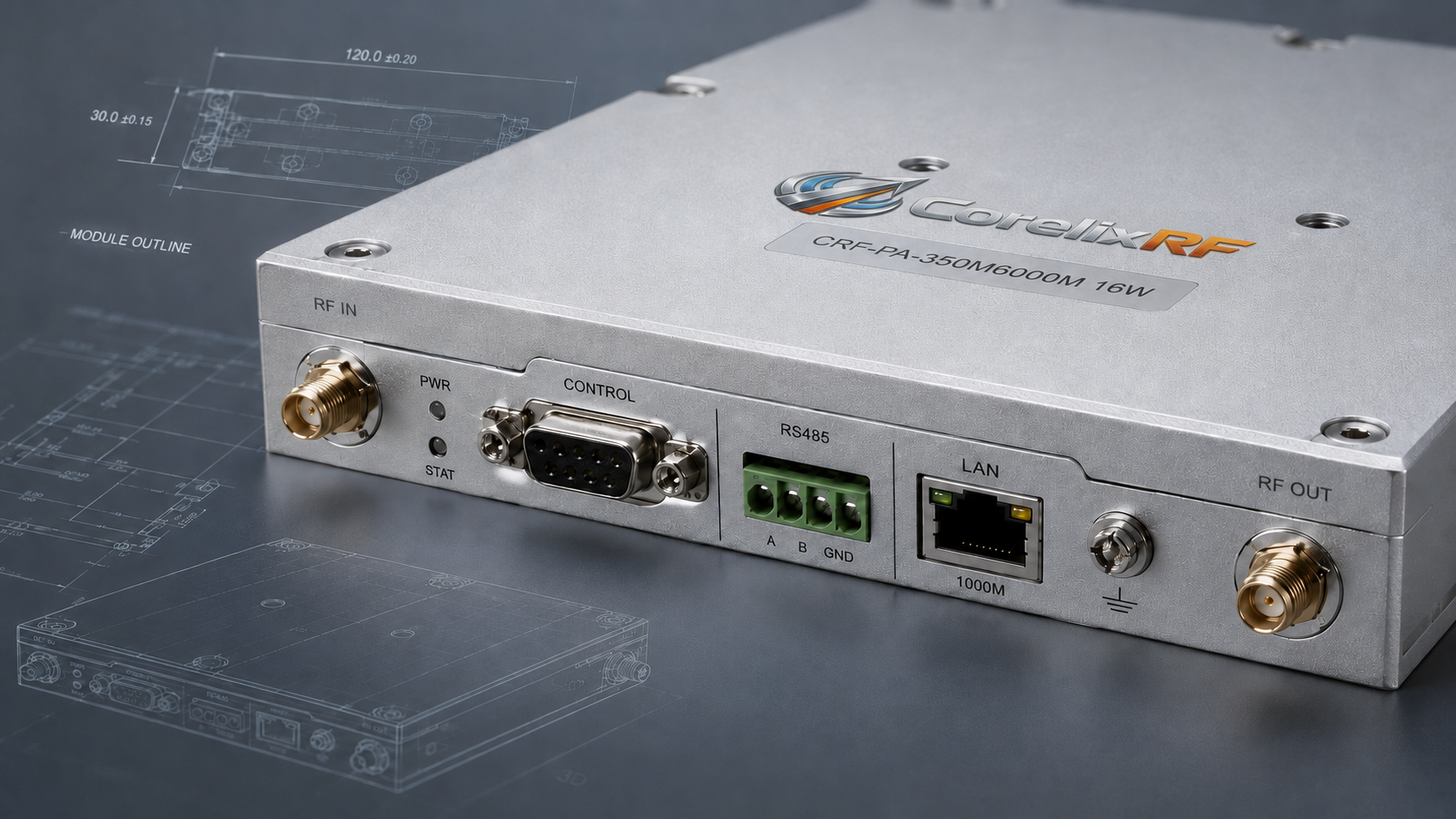
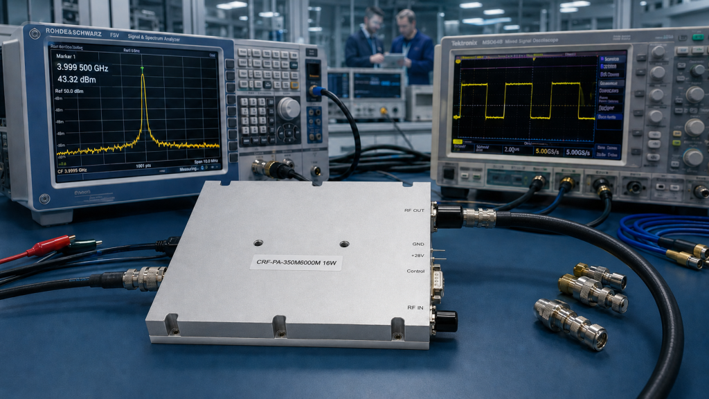
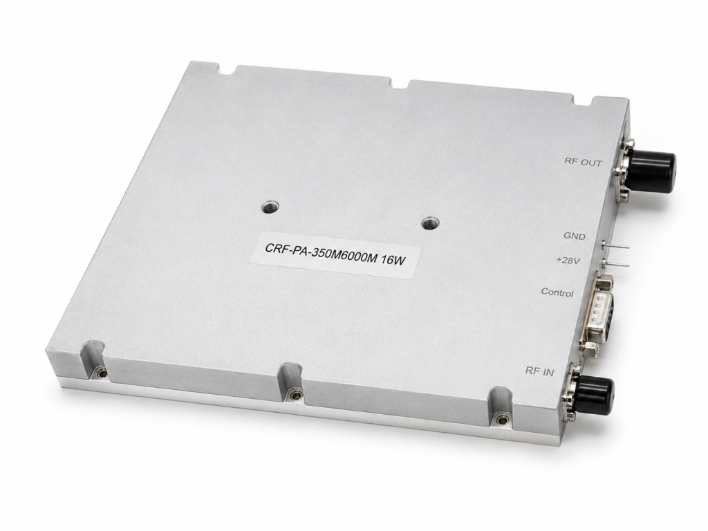
Consider the CRF-PA-350M6000M-16W, delivered rapidly based on the standard platform. This module covers the ultra-wideband frequency range from 350 MHz to 6000 MHz, with a rated output power of 16 W, and provides a minimum small-signal gain of 46 dB. Because its underlying chain is based on the standard platform, this device, packaged in a Mini Enclosure, has built-in protection and monitoring logic that has been rigorously verified:
- VSWR and Overload Protection: Equipped with comprehensive over-temperature, over-drive, over-voltage, and highly sensitive VSWR protection and alarm functions.
- Waveform Response Consistency: Whether the customer’s system requires continuous wave (CW) or specific pulse operation, its basic bias network is already physically equipped to handle extremely high duty cycles and low pulse droop, strictly differentiating the testing parameters of the two.
The standard platform enables CorelixRF to provide credible physical data in an extremely short time to customers in test and measurement instrumentation, communication systems, RF interference / EW system-level testing, and aerospace control systems.
What “Rapid Customization” Options Does the Standard Platform Support?
Within the standard platform framework, “rapid customization” is strictly defined within boundaries that do not alter the core RF physical topology. This restrained customization strategy prevents specification exaggeration while maximizing response speed. Customers can rapidly redefine the following items:
- Control and Monitoring Interface Systems: Building on the default RS485 control interface, options such as forward/reverse power monitoring, GPIB programmable control interfaces, or LAN bus/remote control interfaces can be seamlessly integrated upon request.
- Gain and Linearity Adaptation: Supports a maximum 20 dB small-signal gain adjustment to accurately match the input level of the front-end excitation source, preventing final-stage overdrive saturation.
- Mechanical Form Factor and Thermal Adaptation: While ensuring the baseline air cooling and AC 220 V supply (±10%, 50/60 Hz), mechanical dimensions, mounting hole reference planes, or RF interface routing (such as the orientation of the input/output SMA-Female connectors) can be modified according to the final overall system structure.
CorelixRF’s Standardized Delivery and Factory Acceptance Test (FAT) Process
For overseas procurement and quality control teams, the greatest value is not simply a low price, but predictable delivery times and transparent test evidence. Under this standard platform architecture, CorelixRF executes a rigorous technical review mechanism. Upon receiving your system parameter boundaries (such as target frequency range, output power, waveform type, duty cycle, mechanical constraints, and environmental requirements), the engineering team will rapidly output a feasibility assessment and mechanical drawings.
During the delivery phase, we discard meaningless marketing promises and strictly adhere to delivery standards based on the Factory Acceptance Test (FAT) checklist. Every test report meticulously documents the device’s performance under full-load power, specific VSWR conditions, and clearly defined waveform modes (strictly differentiating between CW and Pulse). This package of trust, composed of empirical data, assists procurement and quality departments in confidently completing incoming inspections, fundamentally mitigating project acceptance risks.
Conclusion
By front-loading core RF verification, CorelixRF’s RF Amplifier Standard Platform balances the dual, stringent requirements of complex projects for parameter customization flexibility and rapid delivery times. Procurement departments and engineers no longer need to choose between “long-lead-time customization” and “compromised catalog models.”
To obtain more empirical test data evidence specific to your frequency band project or distributor technical support materials, please proceed with the following step for engineering engagement:
Request review / distributor kit
Turn the standard platform into a controlled customization plan
If your project needs a modified connector, control port, cooling path, enclosure or frequency window, start from the standard platform and define the delta clearly. This helps keep the discussion around lead time, interface risk, acceptance testing and documents instead of vague custom promises.
Recommended next step: send the target band, output power, duty cycle, load condition, control interface, cooling limit and required FAT documents. CorelixRF can map this standard platform lead-time reduction requirement to a standard platform or a controlled customization path.