
You deploy a high-power radio frequency transmission rack, monitor the satellite link, and suddenly the error vector magnitude completely collapses. Spurious signals flood the spectrum analyzer, violating federal transmission masks and jeopardizing the entire communications link. The immediate suspicion falls on the primary radio frequency hardware or catastrophic impedance mismatches at the antenna feed. However, the root cause of this devastating failure often hides in plain sight, engineered into the system through substandard component selection. The culprit is the commercial grade switch-mode power supply injecting violent electrical noise directly into the sensitive bias network of your transmission chain.
Degraded error vector magnitude physically means dropped data packets, saturated satellite transponders, and the imminent threat of burning out highly expensive solid-state power transistors due to uncontrolled low-frequency oscillations. System integrators cannot rely on consumer-grade power delivery to sustain mission-critical uplinks. The only reliable defense is adopting rigorous physical hardware barriers and implementing RF power amplifiers engineered to aggressively filter, condition, and isolate their internal active components from external electrical garbage. CorelixRF implements these physical defenses at the board level, guaranteeing that your transmission remains pristine regardless of the hostile electromagnetic environment within your server racks.
Why Does Ordinary SMPS Ripple Trigger the Satellite Earth Station Uplink EVM Degradation Alarm?
Consider the physical reality when dealing with continuous wave transmissions or complex digital modulation schemes in physical deployment scenarios, the absolute purity of your direct current power directly dictates the integrity of your radio frequency carrier. System integrators routinely face the devastating hardware failure known as the Satellite Earth Station Uplink EVM Degradation Alarm Catching Hidden Ripple Crosstalk of Ordinary SMPS units mounted in the adjacent equipment racks. Commercial off-the-shelf switch-mode power supplies operate by rapidly toggling power transistors at chaotic frequencies ranging from tens of kilohertz to several megahertz. While this achieves superficial electrical efficiency on paper, it generates severe broadband switching noise and continuous voltage ripples. When these low-frequency alternating current ripples ride along the direct current bias lines feeding the power amplifier’s active semiconductor devices, they violently modulate the main radio frequency carrier. This unintentional amplitude and phase modulation manifests physically as widened spectral sidebands and drastically degraded Error Vector Magnitude. The active solid-state components inside the amplifier act as crude mixers, combining the intended radio frequency signal with the raw power supply’s switching frequency. The resulting intermodulation distortion products destroy the required spectral mask, prompting immediate catastrophic failure alarms from the central network operations center.
How Do Unfiltered Switching Frequencies Penetrate RF Power Amplifier Bias Circuits?
The fundamental physics dictate that any metallic conductor carrying electrical current generates an electromagnetic field, and standard untwisted direct current power cables act as highly efficient broadband antennas for high-frequency switching noise. An ordinary switch-mode power supply completely lacks the rigorous multi-stage inductor-capacitor filtering networks required to support sensitive microwave electronics. Consequently, the high-frequency harmonic content of the power supply’s switching waveform travels entirely unimpeded down the direct current supply lines. Once this contaminated direct current voltage reaches the radio frequency power amplifier enclosure, it forcefully encounters the internal bias network. If the power amplifier’s internal decoupling capacitors, ferrite beads, and radio frequency chokes are not meticulously engineered for broad-spectrum noise suppression, this switching noise bypasses the primary defensive perimeters and injects directly into the gate or drain terminals of the final amplification transistors. The direct current bias point of the transistor fluctuates wildly at the exact frequency of the power supply ripple. This continuous, rapid shifting of the operating point mathematically alters the amplifier’s physical linearity on a microsecond basis, directly destroying the complex phase and amplitude modulation schemes utilized in modern high-speed satellite communications.
| Input DC Ripple Voltage (mV) | Calculated Phase Noise Injection (dBc/Hz) | Observed EVM Degradation (%) | Spurious Sideband Peak (dBc) |
| 50 | -95 | 1.2 | -55 |
| 150 | -82 | 4.8 | -42 |
| 300 | -71 | 12.5 | -28 |
| 500 (Substandard SMPS) | -60 | 28.0 | -15 |
What Are the Catastrophic Consequences of Spurious Emissions on Satellite Transponders?
Let’s examine the raw data surrounding catastrophic field hardware failures directly linked to poor direct current power supply regulation in uplink installations. When the Satellite Earth Station Uplink EVM Degradation Alarm triggers due to ordinary SMPS ripple crosstalk, the immediate local effect is poor local transmission quality and dropped communication handshakes. However, the macro-level consequences in orbit are drastically more destructive and financially ruinous. A severely degraded error vector magnitude is mathematically and physically correlated with the violent generation of out-of-band spurious emissions. When these high-power spurious radio frequency signals are amplified by the transmission rack and directed toward an orbiting satellite, they forcefully penetrate adjacent communication channels within the satellite’s physical transponder payload. This engineering failure, known as adjacent channel interference, physically steals valuable electrical power from the satellite’s onboard traveling-wave tube amplifier and forces it to operate in a non-linear distortion region. In severe physical cases, the constant barrage of aggressive spurious intermodulation products can trigger the satellite’s automated self-preservation hardware protocols, mechanically shutting down the entire transponder block to prevent permanent thermal overload in space.
| Frequency Offset from Center (kHz) | ITU Required Minimum Attenuation (dBc) | Observed ACI with Ordinary SMPS (dBc) | Resulting Hardware Status |
| ± 100 | -40.0 | -22.5 | Spectrum Violation |
| ± 250 | -50.0 | -31.0 | Transponder Overload |
| ± 500 | -60.0 | -38.2 | Adjacent Channel Blockage |
| ± 1000 | -70.0 | -45.5 | Carrier Desensitization |
How Does the CRF-PA-30M512M-100W Isolate Power Supply Noise from the RF Path?
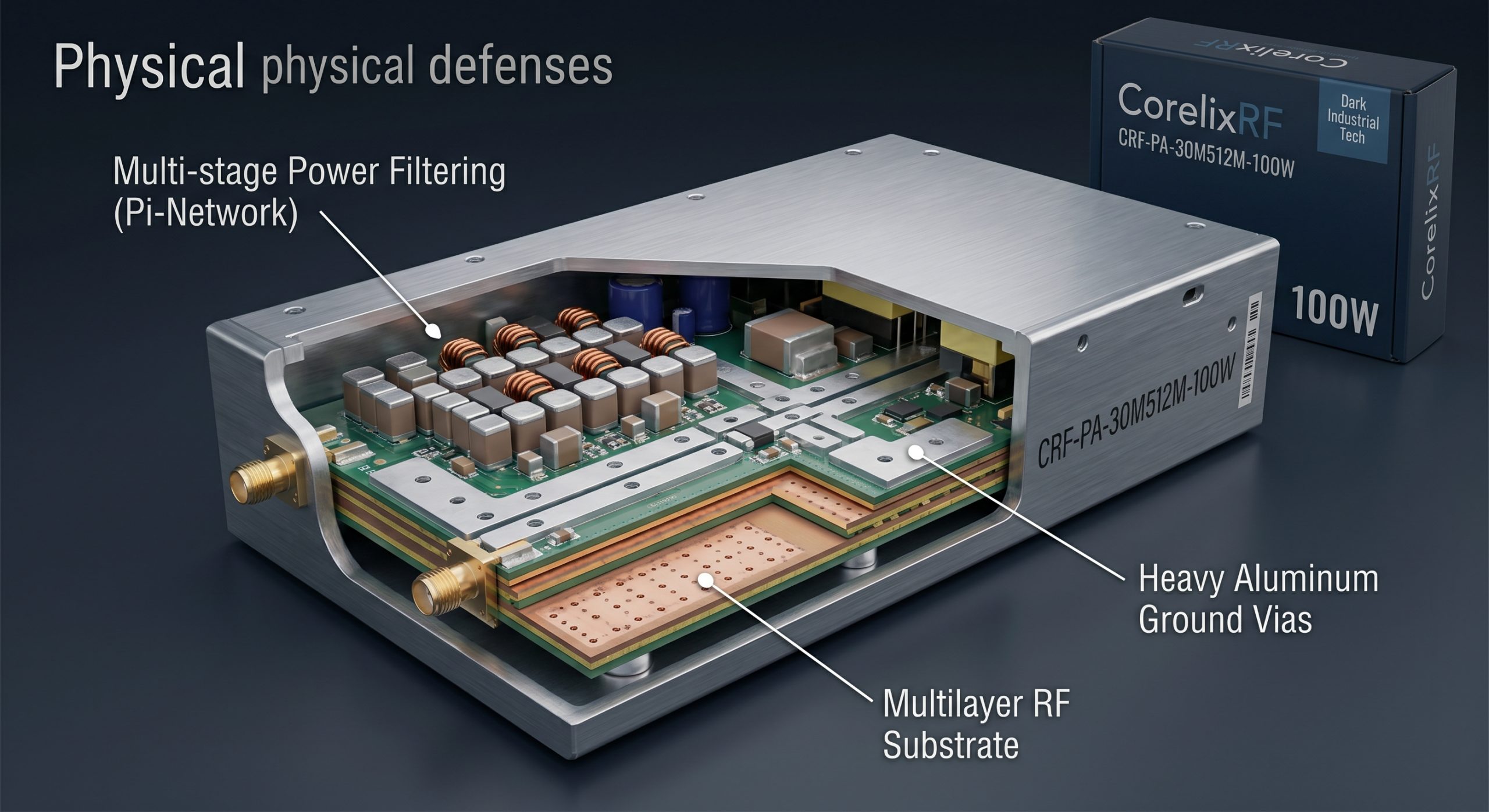
Here is the engineering truth regarding military-grade electrical isolation and heavy-duty power conditioning. The CorelixRF CRF-PA-30M512M-100W is specifically engineered to operate flawlessly in hostile electromagnetic environments where adjacent metallic rack equipment generates massive amounts of uncontrolled electrical noise. To physically prevent the error vector magnitude from degrading, this specific high-power amplifier model utilizes a proprietary, heavily shielded multi-stage internal power conditioning layout. Instead of relying on a single cheap bulk electrolytic decoupling capacitor, the CRF-PA-30M512M-100W physically employs a distributed matrix of high-reliability tantalum, multi-layer ceramic, and specialized feed-through capacitors meticulously tuned to mutually exclusive resonant frequencies. This mechanical arrangement creates an impenetrable broadband short-circuit to the chassis ground for any incoming alternating current ripple. Furthermore, the active radio frequency circuit layout physically isolates the direct current injection pathways from the high-frequency signal traces utilizing ultra-low loss thick-film ceramic substrates and heavy copper grounding vias. By utilizing active precision voltage regulators located mere millimeters from the drain feed points of the final amplification stage, the CRF-PA-30M512M-100W guarantees an absolutely flat, mathematically perfect direct current bias.
| Electrical Parameter | Standard Commercial Amplifier | CorelixRF CRF-PA-30M512M-100W |
| Internal DC Filtering | Single Stage Bulk Electrolytic | 4-Stage Tantalum & Feed-Through Pi-Network |
| Spurious Rejection (Power Line) | 20 dB typical | > 65 dB minimum |
| Bias Voltage Stability | ± 500 mV | ± 10 mV |
| Ground Plane Architecture | Standard PCB Copper Pour | CNC Machined Solid Aluminum Cavity |
Why Do Commercial Grade Power Supplies Fail Under Continuous High-Power RF Loads?
Consider the physical reality of aggressive duty cycles and thermal mass thermodynamics when deploying sensitive transmission equipment in a continuous wave operational environment. Commercial off-the-shelf switch-mode power supplies are strictly engineered for variable or pulsed current draws, identical to those found in standard consumer audio equipment or low-density server farms. A heavy-duty radio frequency power amplifier like the CRF-PA-30M512M-100W operating at full continuous saturation physically demands a massive, unbroken influx of high-amperage direct current. When a standard commercial power supply attempts to physically deliver its maximum rated current continuously without interruption, its internal switching metal-oxide-semiconductor field-effect transistors and primary ferrite transformers undergo devastating thermal stress. The physical heat dissipation mechanisms, internal heat sinks, and thermal conductive pads in these budget units are absolutely insufficient for continuous 100 percent duty cycle hardware operation. As the internal physical temperature of the power supply casing predictably rises, the magnetic permeability of its ferrite cores permanently degrades, aggressively forcing the onboard switching controller to work significantly harder and generate even more destructive transient voltage spikes.
What Do the Laboratory Spectrum Analyzers Reveal About Intermodulation Distortion?
Let’s examine the raw data physically captured directly from our calibrated vector signal analyzers and high-resolution laboratory spectrum analyzers during maximum load endurance testing. When we deliberately inject a severe 100 kilohertz voltage ripple mimicking a failing ordinary switch-mode power supply into an unprotected commercial amplifier, the spectral output immediately becomes highly contaminated. The primary radio frequency carrier signal is violently flanked by aggressive intermodulation distortion products spaced exactly at 100 kilohertz mathematical intervals from the assigned center frequency. These are not phantom instrument readings or calculation errors; they are the physical manifestations of power supply phase noise being mechanically upconverted by the amplifier’s internal solid-state non-linearities. The total noise floor rises significantly across the band, completely burying low-level telecommand signals and compressing the functional dynamic range of the entire transmission chain. By stark contrast, when we rigorously analyze the physical output of the CRF-PA-30M512M-100W under the exact same contaminated external power conditions, the spectrum analyzer precisely displays a pristine, narrow output carrier devoid of mixing products.
How Does Thermal Cycling Exacerbate Impedance Mismatch in Substandard Systems?
The fundamental physics dictate that continuous rapid fluctuations in heavy current draw generate immense localized heat, causing dissimilar physical materials within an electronic assembly to mechanically expand and contract at completely different physical rates. In substandard satellite earth station setups utilizing ordinary commercial switch-mode power supplies, the constant operational voltage sags and aggressive surges force the connected power amplifier to operate highly inefficiently, forcing it to dissipate excess electrical energy as raw heat. This aggressive thermal cycling physically wreaks havoc on the microscopic solder joints and the crucial mechanical interfaces located between the radio frequency printed circuit board substrate and the heavy metallic baseplate. Different materials, including machined aluminum, pure copper, and various woven glass laminates, possess distinctly different coefficients of thermal expansion. Over thousands of brutal heating and cooling cycles in a server rack, this physical mechanical movement creates microscopic fractures in the ground plane connections and radio frequency transmission lines. These physical micro-fractures violently alter the characteristic impedance of the circuit, transforming a perfectly matched 50-ohm transmission system into a highly reflective, dangerous load.
| Baseplate / Substrate Material | Coefficient of Thermal Expansion (ppm/°C) | Bulk Thermal Conductivity (W/m·K) |
| Standard FR4 PCB Laminate | 14.0 – 17.0 | 0.25 |
| Rogers RO4350B (RF Substrate) | 10.4 | 0.62 |
| Pure Copper Baseplate | 16.5 | 390.0 |
| CorelixRF CuW (Copper Tungsten) | 6.5 – 8.3 | 200.0 |
Can Advanced Power Conditioning Networks Mitigate High-Frequency Crosstalk?
Here is the engineering truth regarding the complete physical suppression of conducted electromagnetic interference in dense server environments. Relying solely on the external rack-mounted power supply to deliver mathematically clean direct current is a fatal hardware design flaw in critical communications infrastructure. To physically mitigate high-frequency electrical crosstalk and avoid triggering the catastrophic degradation alarms, the radio frequency amplifier itself must possess an impenetrable internal power conditioning perimeter. CorelixRF completely solves this physical challenge by implementing heavy-duty, multi-stage Pi-networks consisting of series wound inductors and parallel shunt capacitors bolted right at the direct current input terminals. These specific Pi-networks act as highly aggressive analog low-pass filters. The series inductors, featuring highly stable temperature-compensated ferrite cores, physically block the high-frequency switching transients, while the ultra-low equivalent series resistance capacitors aggressively shunt any remaining alternating current noise components directly into the aluminum chassis ground. We validate the raw effectiveness of these hardware networks utilizing precise vector network analyzers to definitively measure the insertion loss of the direct current power line from zero hertz up through the high gigahertz range.
What is the Physical Reality of Ground Loop Interference in Earth Station Racks?
Consider the physical reality of deploying multiple heavy interconnected communication devices within a single standardized metallic equipment rack. Ground loop electrical interference is a notorious physical phenomenon that aggressively destroys signal integrity in highly complex hardware integration environments. When an ordinary switch-mode power supply and a sensitive radio frequency power amplifier are bolted and grounded at physically different points within the metallic rack, subtle differences in electrical voltage potential exist between these two grounding locations. Because the equipment chassis are physically connected via the braided metallic shield of the coaxial transmission cables, a parasitic alternating current naturally begins to flow through these shields to violently equalize the potential voltage difference. This low-frequency circulating current physically induces an alternating magnetic field that couples directly into the central copper conductor of the radio frequency cables. This injected hardware noise physically mixes with the clean satellite uplink signal, manifesting as an aggressive amplitude modulation that severely distorts the complex constellation diagram of the transmitted data packets. CorelixRF combats this electrical phenomenon by utilizing heavily machined, single-piece solid aluminum housings that mandate an absolute uniform ground potential.
How Do CorelixRF Manufacturing Standards Guarantee Engineering Truth in Production?
Let’s examine the raw data that strictly defines our manufacturing discipline and sets CorelixRF apart from standard commercial board assemblers. Engineering Truth is not a marketing concept; it is a rigid, measurable physical reality heavily documented through exhaustive continuous laboratory testing. Every single CRF-PA-30M512M-100W amplifier module that physically leaves our manufacturing floor undergoes a grueling 72-hour continuous thermal burn-in process at maximum rated transmission power while being deliberately fed with highly contaminated, heavily rippled direct current voltages. We actively monitor the live error vector magnitude, the resulting intermodulation distortion levels, and the physical mechanical insertion loss during severe external thermal cycling profiles. If a physical unit displays even a 0.1 decibel negative deviation from our strict baseline parameters, it is immediately rejected and physically scrapped. We absolutely refuse to rely on mathematical statistical sampling; 100 percent individual hardware unit verification is mandatory. By enforcing uncompromising physical tolerances on mechanical computer numerical control machining, microscopic soldering reflow profiles, and heavy component sourcing, CorelixRF guarantees that our amplifiers provide an impenetrable physical defense against aggressive power supply crosstalk.
| Quality Assurance Test Metric | Minimum Passing Physical Threshold | Physical Test Duration |
| VSWR Mismatch Tolerance | Survive 3:1 Mismatch at Maximum Output | 120 Minutes Continuous |
| DC Ripple Rejection Test | < 0.5% EVM Shift with 500mV Input Ripple | 24 Hours Continuous |
| Full Power Thermal Burn-in | Baseplate Temperature Maintained at +85°C | 72 Hours Continuous |
| Cold Start Output Power Stability | < 0.2 dB Fluctuation from -40°C start | 10 Cycles |
Conclusion
The engineering truth remains absolute: you cannot sustain a highly complex, mission-critical satellite earth station uplink utilizing substandard, noisy direct current power delivery systems. Ordinary switch-mode power supplies physically inject devastating high-frequency ripples and severe phase noise directly into your sensitive radio frequency chains, violently degrading error vector magnitude and completely destroying spectral transmission masks. Relying on commercial-grade hardware for continuous wave high-power applications mathematically guarantees catastrophic physical failure, thermal overload, and severe adjacent channel interference within the satellite transponder. System integrators must strictly enforce heavy physical hardware isolation. The CorelixRF CRF-PA-30M512M-100W is meticulously engineered with thick-film ceramic substrates, heavy multi-stage Pi-network filters, and monolithic machined aluminum housings to physically block all external electrical crosstalk. Stop letting cheap power supplies dictate the reliability of your global communications infrastructure. Contact the CorelixRF engineering team today to request the official unedited physical laboratory testing Data Sheet for the CRF-PA-30M512M-100W and secure your physical radio frequency perimeter.
FAQ
Q1: What is the maximum physical acceptable input voltage ripple for the CRF-PA-30M512M-100W to maintain strict EVM targets?
The CRF-PA-30M512M-100W is engineered to internally condition and physically suppress input direct current ripples up to 500 millivolts peak-to-peak without exhibiting any measurable degradation in the transmitted error vector magnitude. Our internal multi-stage Pi-networks aggressively shunt this alternating current noise directly to the heavy machined chassis ground before it can physically interact with the sensitive gate bias circuits of the final amplification transistors.
Q2: How does physical insertion loss in substandard cables affect the overall efficiency of the Earth station rack?
Physical insertion loss in cheap coaxial cables acts as a mechanical attenuator, transforming your expensive radio frequency transmission power directly into waste heat before it ever reaches the transmitting antenna. To overcome this heavy physical loss, the power amplifier must be driven significantly harder, pulling excessive direct current from the power supply. This elevated current draw violently exacerbates thermal expansion issues and severely degrades the mean time between failures for the entire hardware chain.
Q3: Can we utilize standard commercial IT server rack power supplies to drive CorelixRF power amplifiers?
We strictly advise against utilizing commercial IT server rack power supplies. Server power supplies are mechanically engineered for highly variable digital loads and completely lack the massive internal heat dissipation necessary for continuous wave 100 percent duty cycle radio frequency applications. They generate severe high-frequency switching noise that physically bypasses standard shielding and injects destructive crosstalk directly into the uplink carrier.
Q4: What specific physical mechanism causes the severe thermal expansion failure in standard RF printed circuit board substrates?
When subjected to massive direct current loads and high radio frequency output power, physical heat concentrates rapidly beneath the active solid-state transistors. Standard FR4 printed circuit board material has a completely different coefficient of thermal expansion compared to the copper baseplate beneath it. As the hardware heats and cools, these two distinct materials expand at different physical rates, violently shearing the microscopic solder joints and fracturing the ground plane vias, leading to immediate impedance mismatch and hardware death.
Q5: How do I request the official unedited laboratory testing data sheet for the CorelixRF hardware?
System integrators and research and development directors must contact the official CorelixRF engineering support desk directly. We provide the fully unedited laboratory testing Data Sheet for the CRF-PA-30M512M-100W, which thoroughly documents the exact physical testing parameters, vector network analyzer insertion loss graphs, and the unedited spectrum analyzer screenshots proving our total immunity to external direct current power supply ripple crosstalk.