
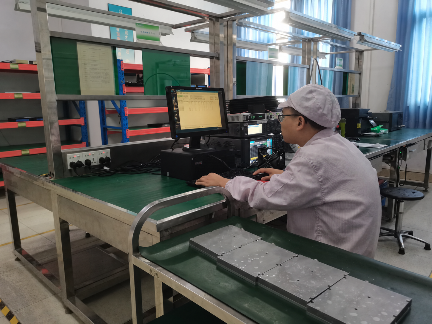
RF amplifier testing should establish output power, gain, gain flatness and thermal behavior under defined operating conditions. Start by agreeing on the frequency range, input drive, measurement reference planes, waveform, load and cooling. Results become comparable only when the relevant conditions are recorded with them.
Use this guide to plan RF power amplifier testing: define the conditions, select the measurements, and record the results needed for engineering review. A reading at one frequency or a short power run does not establish performance across every operating condition.
1. Define the test conditions first
Write down what each test must establish before selecting the measurement settings. The same amplifier can produce different readings when the drive level, cable path, waveform or thermal state changes.
| Test | Conditions to define | Record with the result |
|---|---|---|
| Output power | Frequency, input drive, waveform, load and output reference plane | Corrected power, power definition and path correction |
| Gain and gain flatness | Input/output reference planes, frequency steps and operating region | Input power, output power and gain at each test point |
| CW or pulsed operation | CW state, or pulse width, PRF, duty cycle and measurement timing | CW power, or separately identified peak and average power |
| Thermal behavior | Ambient conditions, mounting, cooling, load and run duration | Temperature location, supply current and power over time |
| Load and protection | Approved mismatch conditions, drive limits and stop conditions | Applied condition, protective response and recovery |
Use the product specification and agreed test plan to set limits. Keep measured values, typical specifications and acceptance limits in separate fields.
2. Measure output power at a defined reference plane
Output power testing confirms whether the amplifier delivers the required RF level under the stated conditions. Specify whether the result applies at the amplifier output connector, after a cable, at another device’s input or at an antenna feed. Loss between those points changes the reading.
A power-test path can include a signal source, amplifier under test, directional coupler, attenuator, power sensor and rated load. The coupler samples the signal for measurement while the main RF path continues to the load. Account for the coupling factor and losses in the measurement path when referring the reading back to the amplifier output.
Before enabling RF, check the frequency and power ratings of the connectors, cables, coupler, attenuator, load and sensor path. Follow the equipment’s input limits and the amplifier’s supply and cooling requirements. Add a driver amplifier only if the required input drive calls for it.
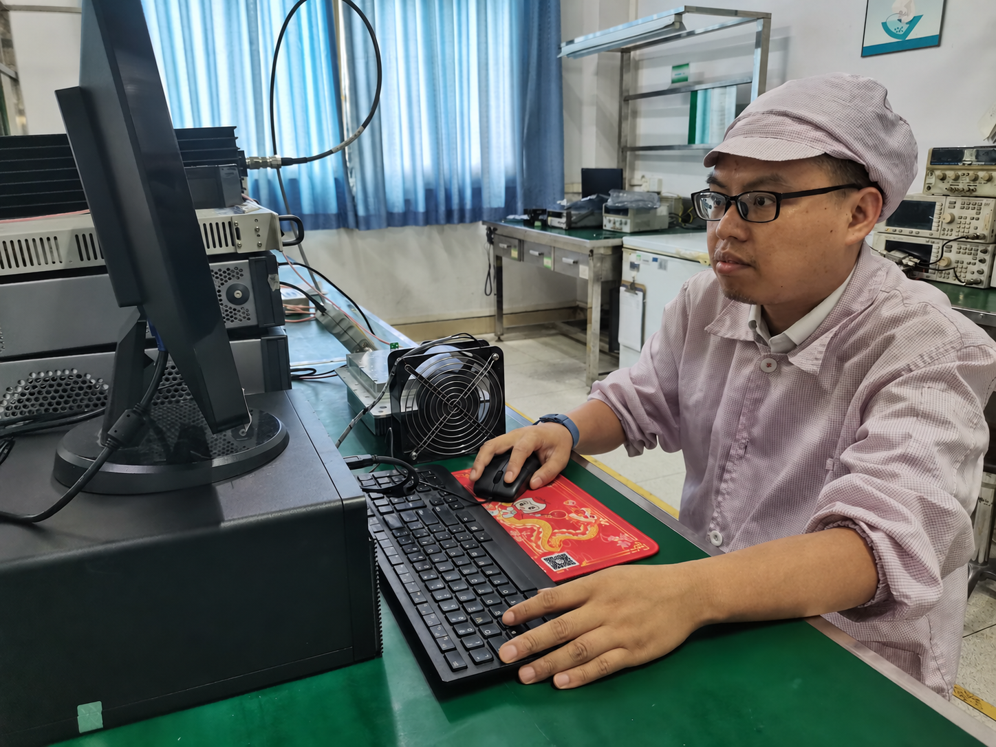
Record the reference planes and corrections with the result. A source setting or sensor display alone does not state the power at the amplifier connector.
3. Check gain and gain flatness across the band
For power measurements at the defined input and output reference planes, gain in dB equals output power in dBm minus input power in dBm. Measure at the frequency points required by the test plan, with the input drive controlled at each point.
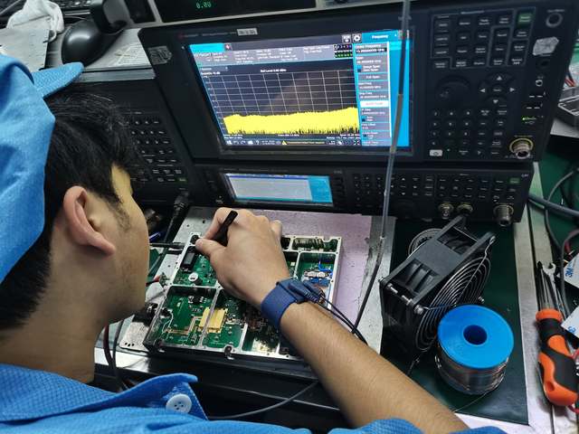
Small-signal gain and gain near compression describe different operating regions. For linear-operation checks, keep the device in the intended region. If the task is to find the compression point, use a defined power sweep; the P1dB measurement guide covers that separate procedure. Saturated output power cannot stand in for linear output capability.
Gain flatness describes gain variation across the frequency range. State the range and how flatness is reported, such as maximum-to-minimum variation or deviation from a reference value. Keep temperature and the RF path consistent, and correct for frequency-dependent cable, switch, coupler and fixture losses.
When the test also requires port matching or S-parameters, follow the RF amplifier VNA measurement steps. Their calibration and reference-plane requirements need to be defined for that measurement.
4. Separate CW and pulsed measurements
CW testing examines continuous output, power stability and thermal behavior under continuous drive. For pulsed testing, record peak power, average power, pulse width, pulse repetition frequency (PRF), duty cycle and measurement timing. Include rise and fall behavior when the application requires it.
For periodic rectangular pulses, duty cycle equals pulse width multiplied by PRF, using consistent units. With constant power during each pulse and negligible RF power between pulses, average RF power equals pulse power multiplied by duty cycle. These relationships do not make a pulsed power rating a CW rating.
Choose a sensor or analyzer and settings that support the pulse format and required time resolution. An average-only reading cannot describe pulse edges or the power variation within a pulse. A CW measurement also needs an engineering basis before it can represent pulsed operation.
For operating-mode selection, see the guide to specifying CW versus pulsed RF amplifiers.
5. Test thermal behavior with the intended cooling
A short output-power check does not establish sustained operation. Define the run duration, ambient temperature, airflow, mounting surface and enclosure arrangement before testing. Monitor output power, supply current and temperature during the run.
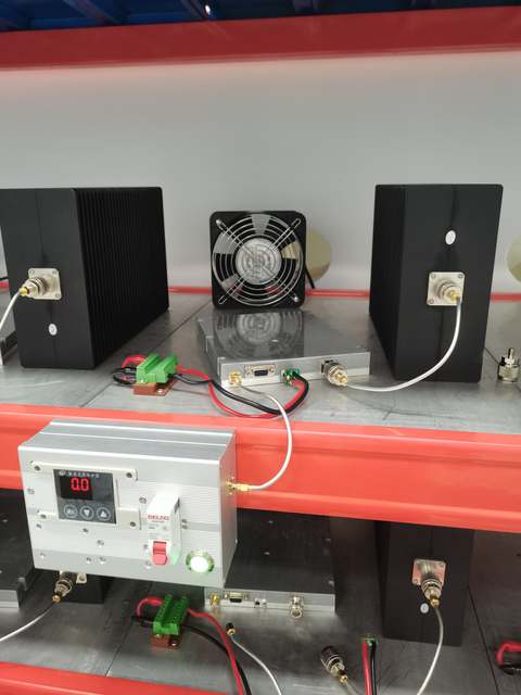
Identify where temperature is measured. Ambient, case, baseplate and junction temperature are different quantities. Keep the product’s required heatsink, airflow or other cooling conditions in the test record.
For pulsed operation, include duty cycle and average power in the thermal assessment; pulse width alone is insufficient. Reduced average RF power does not remove the need to verify cooling. Use the product’s approved operating limits and test plan for stop conditions.
For rack installation details, see the guide to RF amplifier cooling requirements.
6. Review load and protection limits
Antennas, fixtures, switches and test loads can present a mismatch and produce reflected power. An input or output VSWR specification describes matching at that port; it does not by itself establish the amplifier’s ability to survive a mismatched load.
Use an approved protection-test procedure with defined power, frequency, mismatch conditions, duration and temperature. Record the protective response and recovery behavior. Review input overdrive, current limits and interlocks where they apply. Do not infer a protection feature or threshold from a generic product category.
For load-change investigations, see the guide to VSWR and reflected-power protection.
7. Match the test plan to the application
For EMC work, define the required field or injected level and the calibrated RF path. For radar, define pulse power, timing and duty cycle. For communications, include the waveform and linearity requirements. Laboratory work needs repeatable settings and measurement limits; aerospace projects may add agreed environmental and documentation requirements.
These are inputs to a test plan. Product suitability still depends on the specific configuration and requirements. For checks performed on each manufactured unit, the production testing and traceability guide explains coverage, release limits and records.
8. Turn the test plan into useful RFQ inputs
Before requesting an amplifier, prepare the frequency range, required output power and reference plane, source drive, gain target, waveform, CW or pulse mode, load condition, supply, cooling, connector path and test duration. State which results must meet acceptance limits and which are for characterization.
Include the required report format and operating conditions so the supplier can review the same requirement you intend to verify at delivery.
RF amplifier testing FAQ
What should be tested on an RF power amplifier?
Start with frequency coverage, output power, gain, gain flatness, operating mode, thermal behavior and load/protection requirements. Select the actual checks and limits from the product specification and application-specific test plan.
Why does gain flatness testing need path corrections?
Cables, couplers, switches and fixtures can change loss with frequency. Their response can affect the measured variation, so define the reference planes and account for the relevant losses.
Can a short CW test verify pulsed and thermal performance?
It does not cover every pulse condition or establish sustained thermal behavior. Define the waveform, duty cycle, measurement timing, run duration and cooling for each required check.
Send the operating conditions and required test records to CorelixRF to discuss your RF amplifier testing requirements.