
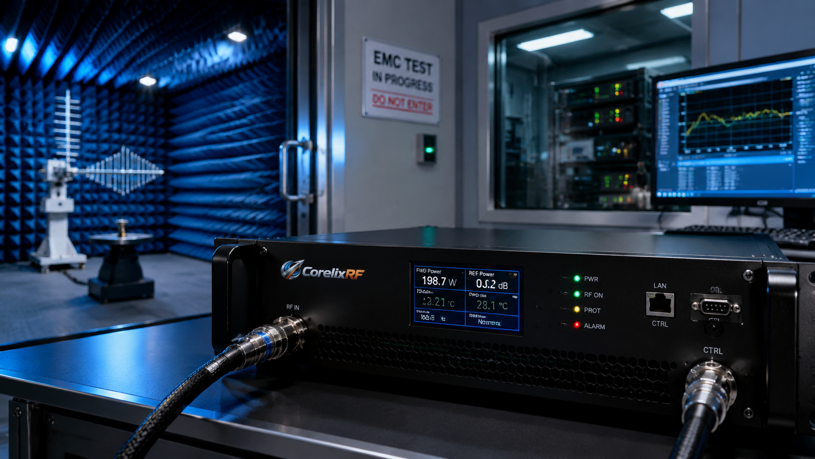
An EMC RF amplifier is usually part of a laboratory system, not a standalone product decision. The amplifier must work with signal sources, couplers, antennas, chambers, probes, loads, calibration procedures, protection devices, and documentation requirements. That makes EMC amplifier content a much richer topic than another frequency-band product article.
CorelixRF’s amplifier platform page identifies EMC amplifier platforms for EMC-related laboratory environments, test platform development, and compliance-oriented RF power support. It also references high-power HF/VHF engineering experience and broader RF power platform coverage. Buyers should still submit exact requirements because EMC work is heavily shaped by frequency range, power level, load path, standards context, and lab configuration.
Define the EMC Test Environment First
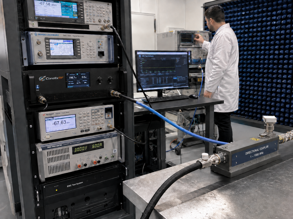
The first planning step is not wattage. It is the test environment. Engineers should define whether the amplifier will drive an antenna, CDN, clamp, fixture, or other coupling path. They should also define the frequency range, required field or injected level, load path losses, calibration method, and duty or dwell time.
Once that environment is clear, the amplifier selection becomes more meaningful. A lab may need a lower-frequency high-power path, a VHF/UHF broadband amplifier, or a custom EMC system review. CorelixRF’s RF power amplifier platform page provides the main entry point for these project-based requirements.
Frequency Coverage and Power Class
EMC amplifier requirements may overlap HF, VHF, UHF, and higher RF regions. If the work sits in VHF/UHF, the 30-512 MHz RF amplifier path can provide standard model context. If the requirement moves into mid-band or microwave testing, CorelixRF’s 300-2700 MHz amplifier and 2-6 GHz amplifier pages help frame the available platform ranges.
The output target should be defined at the test point, not only at the amplifier connector. EMC setups often include couplers, switches, antennas, cable runs, and calibration fixtures. Those losses must be included before selecting a power class.
Controlled Output and Repeatability
EMC labs care about repeatability. The amplifier should support controlled output behavior across the required range, and the system should include enough monitoring and documentation to support internal procedures. Engineers should ask about gain, power behavior, current requirements, cooling, protection, RF connector path, and available validation data.
If the amplifier is part of a new lab system, the RFQ should include a block diagram. This helps the manufacturer understand how the amplifier will interact with the source, directional coupler, power meter, antenna or injection device, load, and control rack.
Cooling, Safety, and Documentation
High-power EMC amplifiers can create serious thermal and operational constraints. Cooling, airflow, enclosure design, interlocks, current draw, and mismatch protection should be reviewed before quotation. The lab should also define what documentation is needed: datasheet, test data, mechanical drawings, connector details, calibration support, or acceptance test information.
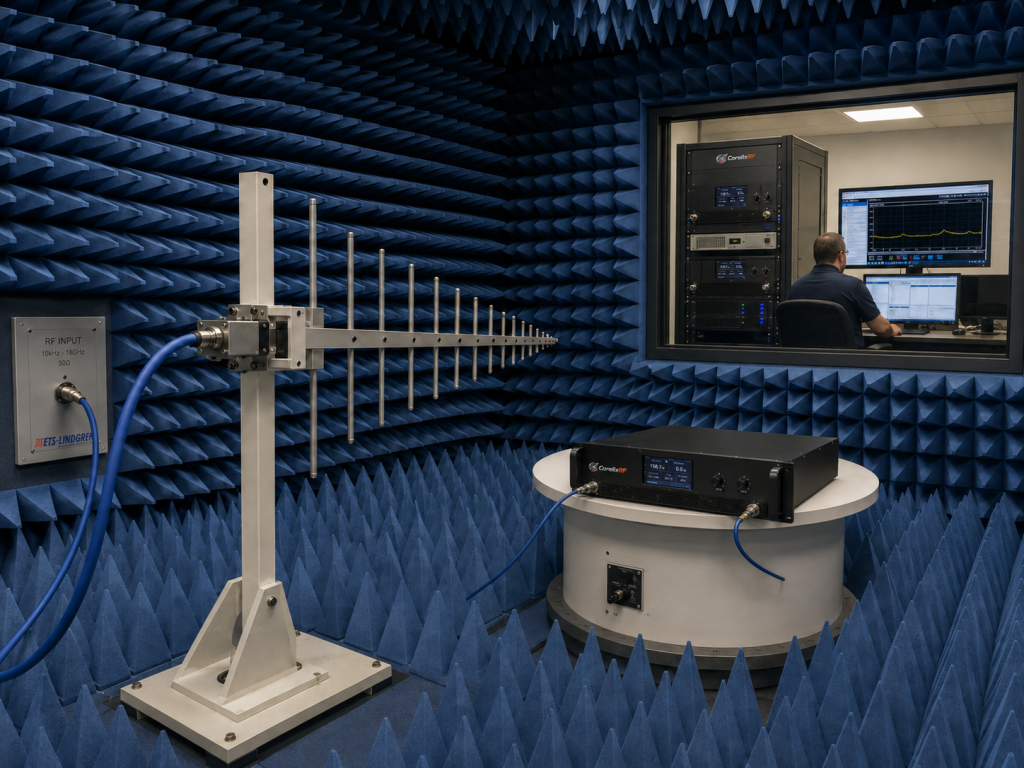
CorelixRF’s Contact page is the right place to submit frequency range, output power, operating mode, antenna or load condition, connector preference, cooling requirement, control interface, and documentation needs.
FAQ
What is an EMC RF amplifier used for?
It supports EMC-related laboratory testing, RF immunity setups, controlled high-power RF delivery, and project-specific test platform development.
Why should output power be defined at the test point?
Because cables, couplers, switches, antennas, fixtures, and loads can create significant losses between the amplifier and the actual test condition.
Can a standard RF amplifier be used in an EMC lab?
Sometimes, but the full test environment, duty cycle, load condition, protection, cooling, and documentation needs must be reviewed first.
What should an EMC amplifier RFQ include?
Include frequency range, required test level, RF path losses, coupling method, operating mode, duty cycle, cooling, connector path, control needs, and documentation requirements.