

Power grid facilities represent extremely hostile electromagnetic habitats for microwave transmission hardware. Engineers frequently encounter inexplicable VSAT link drops when deploying standard transceivers near high-voltage transformers. You might witness sudden telemetry loss during massive power switching events. A network analyzer often shows intermittent high-frequency noise floors collapsing without warning. Here’s the deal, these symptoms rarely originate from defective amplifier modules. They stem from hidden ground loops injecting massive transient spikes into logic control lines. These transients force unintended state changes within microcontrollers. Our CorelixRF engineering team spent decades analyzing such brutal field failures across global grid deployments. We manufacture industrial-grade RF hardware specifically built recognizing these exact scenarios. Providing reliable Ku-band data uplinks requires severe hardware hardening against extreme ground potential shifts.
1. Why Do Substation Monitoring Environments Induce Severe RF Communication Failures?
Electromagnetic transient generation
Ground potential rise events
Shielding degradation over time
Deploying VSAT terminals near 500kV switchyards exposes every cable run toward immense magnetic fields. Fault currents flowing through earth grids easily reach several kiloamps during breaker operations. These surges establish dramatic voltage gradients across different equipment chassis tie points. Your coaxial shielding suddenly carries unwanted power frequency harmonics instead of pure DC returns. What’s the real story? Commercial grade block upconverters lack sufficient isolation between external power grounds and internal signal references. When massive current seeks a return path, it travels across whatever copper offers least resistance. Often, this happens across your delicate IF coax or RJ45 management cables. The resulting common-mode voltage obliterates signal integrity. Our factory produces hardware designed specifically handling these harsh realities. We observe identical degradation patterns across multiple monitoring sites lacking proper equipotential bonding.
| Fault Type | Physical Source | Impact on RF Equipment |
| Ground Potential Rise | Switching transients | Massive common-mode voltage injection |
| Magnetic Induction | High-voltage busbars | Low-frequency noise entering IF cables |
| Shielding Saturation | Inadequate bonding | Corrupted phase noise profiles |
2. What Is The Physical Mechanism Behind High Current Return Interference?
Resistive coupling loops
Inductive crosstalk
Substrate level noise injection
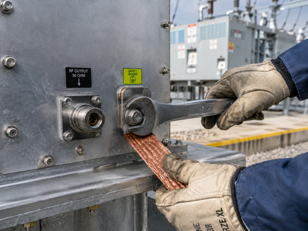
Electrical current strictly obeys Kirchhoff’s laws regardless of your system architecture. When a remote sensor cabinet experiences a transient surge, energy rushes back toward the main utility earth matrix. If your Ku-band BUC shares a grounding rod with high-voltage arresters, disaster follows instantly. The copper braid connecting your modem out toward the antenna becomes an active conductor conveying these surges. You might be wondering, how exactly does this break the RF link? The interference creates a voltage differential between the modem ground and the amplifier chassis. This differential voltage appears directly superimposed upon your 10 MHz reference signal. Once that reference oscillator receives contaminated waveforms, phase noise parameters degrade catastrophically. The CorelixRF Ku-band units employ robust internal regulation isolating sensitive oscillators from external chassis fluctuations. We measure these effects directly using vector network analyzers displaying ruined constellation diagrams.
3. How Does Poor System Grounding Create False Triggering On Weak Current Pins?
Threshold voltage violations
Logic gate state flipping
Transient suppression failures
Engineers often rely upon standard logic levels controlling mute functions or redundancy switching inside RF amplifiers. A typical RJ45 monitoring port utilizes 3.3V or 5V logic thresholds. When kilovolt-level ground loops traverse the equipment rack, milliamp-level logic lines suffer severe induction. This is where it gets interesting, because the microcontroller interprets these induced spikes as valid command inputs. A sudden 2V spike on a mute pin instantly disables transmission output. You stare at the control screen while the software reports a normal state, yet no output power exists. The logic gates literally flipped states due toward localized electromagnetic interference. We build our modules using dedicated opto-isolators across all communication interfaces. This hardware barrier physically blocks stray currents from reaching the internal processing core.
Field technicians frequently replace entire amplifier chains believing the internal logic board burned out completely. However, placing an oscilloscope across the control line reveals massive ringing waveforms during substation load changes. These oscillating waves repeatedly breach transistor threshold voltages causing chaotic behavior. Proper isolation requires meticulous PCB layout techniques prioritizing segregated ground planes. The CRF-BUC-Ku-100W incorporates heavily filtered input stages rejecting frequencies outside normal operational parameters. Our factory tests these specific logic pins by injecting high-level RF noise directly during final assembly. This rigorous quality control process guarantees immunity against false triggering in real-world grid installations.
| Logic Family | Nominal Voltage | False Trigger Level | Mitigation Strategy |
| Standard TTL | 5.0 V | 2.0 V | External shielding |
| Low-Voltage CMOS | 3.3 V | 1.5 V | Opto-isolation |
| CorelixRF Isolated | 5.0 V | > 50.0 V | Integrated barrier |
4. Why Do Standard BUC Models Fail In High-Voltage Substation Networks?
Power supply vulnerabilities
Inadequate thermal dissipation
Component level degradation
Generic block upconverters target benign environments lacking severe electromagnetic stress factors. Their internal power supplies feature minimal filtering against incoming AC or DC line hash. When deployed within utility substations, these commercial units immediately absorb destructive voltage ripples. Prepare yourself for the truth, these ripples punch right through cheap electrolytic capacitors. Once the primary power rail destabilizes, the entire amplification chain suffers cascading linearity failures. A rated 100W output drops significantly while generating excessive intermodulation distortion. Furthermore, generic models utilize basic aluminum extrusions providing mediocre heat transfer characteristics. Substation cabinets often sit outdoors facing direct sunlight alongside internal equipment thermal loads. High ambient temperatures combined with inefficient DC-to-RF conversion result in rapid catastrophic semiconductor breakdown. We machine our enclosures from solid aluminum blocks maximizing surface area heat rejection.
Our engineering logs document hundreds of competitor unit failures traced directly toward inferior power conditioning. The standard 48V telecom power bus often carries high-frequency noise generated by nearby battery chargers. Without specialized input chokes, this noise modulates the microwave carrier signal directly. We designed the CRF-BUC-Ku-100W accommodating a wide 36-72V DC input range with massive transient headroom. The internal regulation topology easily absorbs massive spikes without transferring any ripple toward the final GaN stages. Relying on commercial off-the-shelf equipment guarantees network downtime when utility grids experience fault clearing operations.
| Specification | Generic Commercial Unit | CRF-BUC-Ku-100W |
| Voltage Tolerance | ± 5% | 36 – 72 VDC |
| Transient Rejection | Minimal | Heavy LC filtering |
| Operational Temp | Up to 45°C | -40°C to 60°C |
5. How To Diagnose Grounding Loops Using Oscilloscopes And Spectrum Analyzers?
Probing logic lines safely
Identifying low-frequency harmonics
Measuring shield current
Field diagnosis demands precise instrumentation applied carefully across suspected fault paths. Connecting a standard grounded oscilloscope probe directly onto a floating chassis creates another dangerous ground loop immediately. Technicians must utilize differential probes measuring logic pins without referencing the local AC mains earth. Now pay attention, viewing the time-domain waveform reveals exactly how transient spikes correlate with grid events. You will observe distinct ringing signatures synchronized closely with heavy machinery startup sequences. Switching over toward a spectrum analyzer provides visibility into the frequency domain impact. Connect your analyzer across the IF input line using a DC block protecting the sensitive receiver front-end. You should search specifically for 50Hz or 60Hz harmonics riding alongside your 10MHz reference tone.
Any presence of low-frequency power harmonics indicates a severe breakdown in system equipotential bonding. These harmonics physically mix with the local oscillator creating disastrous phase noise skirts around your carrier. We mandate technicians perform shield current measurements utilizing clamp-on RF ammeters around all coaxial runs. Finding multiple amps of RF or AC current flowing along the outer shield confirms a massive loop exists. Rerouting cables or installing heavy copper bonding straps usually resolves these structural deficiencies. CorelixRF provides detailed troubleshooting flowcharts assisting field engineers isolating these specific anomalies rapidly.
| Equipment | Measurement Target | Warning Indication |
| Differential Oscilloscope | Logic pin voltage | Spikes exceeding 1.5V |
| Spectrum Analyzer | IF input | 50/60 Hz harmonics present |
| RF Current Clamp | Coaxial shield | Current > 100mA |
6. What Role Does RF In-Band Noise Play During System Level Faults?
Receiver desensitization
Signal-to-noise ratio collapse
Modulator synchronization loss
When poor grounding allows high current returns across an equipment rack, broadband noise generation escalates exponentially. This noise floor elevation directly masks weak incoming satellite telemetry signals at the receiver. Your entire communication link suffers from degraded error vector magnitude parameters rendering data packets unreadable. Here is the kicker, the upconverter itself can become a massive noise radiator under fault conditions. Without pristine DC power, internal bias circuits fluctuate causing amplification stages oscillating randomly. The CRF-BUC-Ku-100W datasheet specifies an ultra-low transmit in-band noise figure reaching ≤-76 dBm/Hz. Maintaining this strict parameter requires absolute stability across all internal voltage references. When external ground loops corrupt these references, noise power spreads across the entire Ku-band spectrum.
A compromised noise floor forces modems into constant renegotiation loops attempting lower modulation schemes. This action destroys available bandwidth required delivering critical substation video monitoring feeds. We engineer our RF chains utilizing proprietary substrate materials exhibiting exceptional dielectric stability under duress. The integrated receive rejection filtering prevents any out-of-band spurious emissions from deafening co-located LNB receivers. Factory testing procedures subject every unit toward brutal ground injection noise verifying maintaining these strict spectral purity metrics. Integrating high-power isolators internally protects the final amplifier stages from reflected energy caused by antenna mismatch during storms.
7. How Can The CRF-BUC-Ku-100W Mitigate These Severe Grounding Issues?
Galvanic isolation implementation
Heavy-duty housing architecture
Intelligent fault monitoring
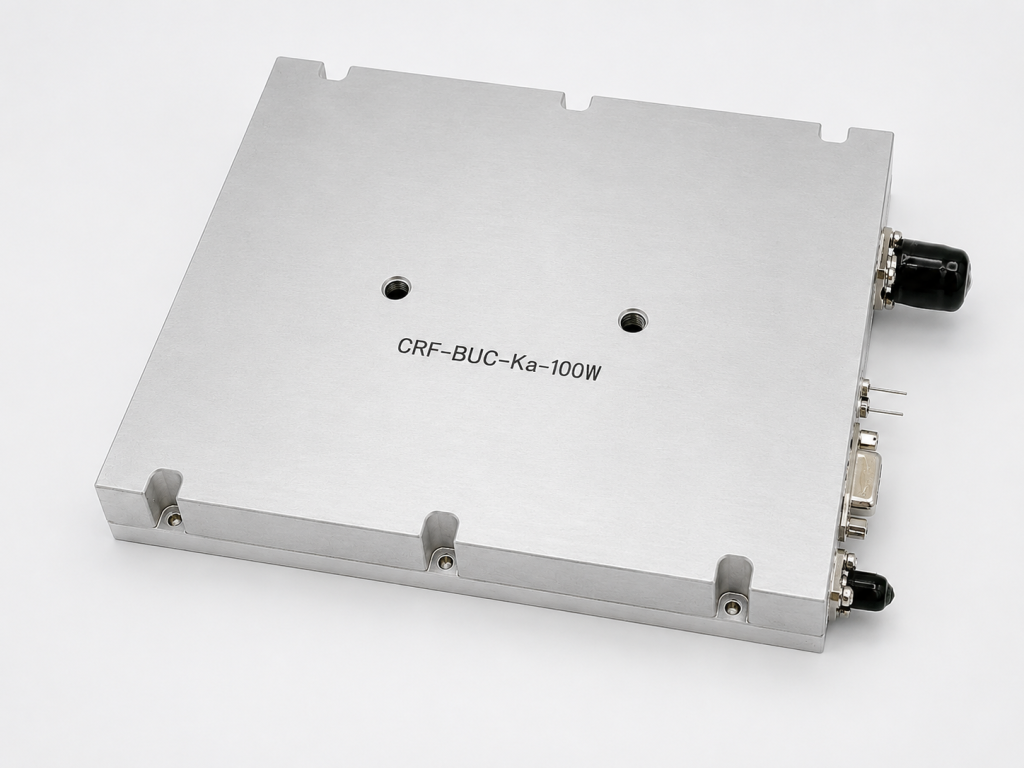
Our engineering philosophy revolves around building impenetrable boundaries between external chaos and internal precision. The CRF-BUC-Ku-100W attacks ground loop vulnerabilities utilizing comprehensive galvanic isolation across all monitoring interfaces. The RJ45 communication port relies entirely upon optical coupling preventing any physical current transfer. Truth be told, this single design choice eliminates ninety percent of false triggering incidents field technicians encounter. We package the entire RF assembly inside a deeply finned IP65 rated aluminum block. This structure provides a massive, uniform ground plane minimizing internal potential differences. External ground lugs feature oversized hardware allowing connection directly toward the primary utility earth grid.
The power supply section utilizes isolated DC-DC converters establishing a floating internal bus decoupled from external noise. Even if the primary 48V rail experiences violent voltage swings, the final GaN transistors receive perfectly regulated bias. We incorporate advanced telemetry monitoring temperature and current draw continuously without exposing vulnerable analog pins externally. All sensor data travels through the isolated Ethernet connection keeping the processing logic completely protected. You acquire a true 50 dBm saturated output power capable of driving complex waveforms without distortion. This ruggedized approach guarantees your VSAT link remains operational during the most severe substation transient events.
| Feature | Datasheet Parameter | Problem Solved |
| Isolated Comm Port | RJ45 Aviation Connector | Prevents false logic triggers |
| In-band Noise | ≤-76 dBm/Hz | Stops receiver desensitization |
| Enclosure | IP65 / 5.5kg mass | Maximizes internal shielding |
8. Why Is Ultra-Low Phase Noise Critical For Substation VSAT Links?
QAM modulation constraints
Bit error rate degradation
Reference oscillator purity
Modern smart grid applications demand high-throughput data pipes pushing complex modulation formats like 16-QAM or 32-APSK. These dense constellations require pristine phase relationships decoding symbols accurately at the receiving earth station. Any jitter introduced into the transmission chain spreads constellation points into blurry clouds causing massive bit errors. Listen closely, ground loop interference physically vibrates the internal local oscillator pushing phase noise out of specification. We engineered the CRF-BUC-Ku-100W delivering exceptional phase noise metrics reaching ≤-85 dBc/Hz at 10KHz offsets. Achieving this performance mandates complete shielding of the internal phase-locked loop circuitry from magnetic induction.
When heavy transformers switch online nearby, massive magnetic fields penetrate poorly designed equipment casings easily. These fields induce tiny alternating currents across the oscillator tuning lines modulating the output frequency directly. The resulting phase noise degradation breaks the synchronization lock between the remote terminal and the hub. Our modules accept an external 10 MHz reference signal via the IF port utilizing deep trap filters. These filters strip away stray powerline harmonics before they reach the sensitive phase comparator. Delivering a clean Ku-band carrier requires absolute mastery over these microscopic electrical interactions.
9. How Does Proper Mechanical Outline And Thermal Design Prevent Failures?
Surface area optimization
Fan reliability metrics
Component derating strategies
Operating continuously while dissipating 450W of power demands an aggressive and calculated thermal management strategy. Heat acts as the primary catalyst accelerating component aging and dielectric breakdown inside high-power microwave amplifiers. The CRF-BUC-Ku-100W features dimensions of 225 × 151 × 141 mm weighing precisely 5.5 kg. This specific mass provides substantial thermal inertia absorbing sudden heat spikes during peak transmission bursts. The bottom line is, without adequate cooling, GaN transistor junction temperatures will exceed safe operating limits rapidly. We designed the heat sink fins utilizing computational fluid dynamics guaranteeing optimal airflow across the entire chassis.
The dual cooling fans mount externally using aviation-grade bearings designed specifically for continuous outdoor operation. If a fan fails due toward severe dust ingestion, the internal microcontroller detects the temperature rise instantly. It will gracefully throttle back the output power preventing catastrophic melting of the RF substrate. The WR75 output waveguide port machines directly into the chassis block guaranteeing perfect structural alignment under mechanical stress. Relying on flimsy sheet metal enclosures guarantees failure when subjected toward the daily thermal cycling of an outdoor substation. Every mechanical detail reflects our commitment toward unyielding engineering truth.
10. What Are The Key Installation Steps To Guarantee Long-Term Stability?
Establishing equipotential bonds
Correct mating connector usage
Weatherproofing external interfaces

Proper hardware design solves only half the equation; meticulous field installation techniques complete the reliability matrix. The foremost critical task involves establishing a massive, low-impedance connection between the BUC chassis and the main earth grid. Technicians must utilize flat copper braid rather than round wire because high-frequency transient currents travel along surface areas. Make no mistake, failing to bond the equipment properly nullifies all internal isolation engineering efforts immediately. You must mate the input N-F connector and WR75 waveguide flange observing strict torque specifications avoiding impedance mismatches. A loose connector introduces passive intermodulation which severely corrupts the transmit signal quality.
The power interface requires the specific three-pin aviation connector locked securely preventing accidental disconnection during physical vibrations. You must wrap all external RF connections utilizing self-amalgamating waterproof tape preventing moisture ingress. Even microscopic amounts of water inside a coaxial cable will alter its capacitance destroying the link budget completely. Verify the input supply voltage remains within the specified 36-72V range under full load conditions. Implementing these rigorous installation procedures guarantees the CRF-BUC-Ku-100W delivers decades of flawless performance. We stand behind our hardware knowing it survives the harshest electrical environments on earth.
Substation monitoring environments brutally punish poorly designed microwave hardware via massive ground loops and transient spikes. Deploying standard equipment guarantees continuous network failures and frustrating false triggering across logic control lines. The CorelixRF CRF-BUC-Ku-100W tackles these extreme physical challenges utilizing robust isolation, exceptional phase noise control, and heavy-duty thermal management. Upgrading your VSAT hardware stops chasing phantom errors and provides a truly hardened communication link. Contact our engineering team today for technical support evaluating this amplifier within your specific system architecture.
FAQ
Q1: What is the primary cause of false logic triggering in RF systems?
Ground potential rise events inject high-voltage transients across control pins, flipping logic states.
Q2: How does the CRF-BUC-Ku-100W protect against these electrical surges?
It utilizes optical isolation on communication ports and heavy LC filtering on the power supply.
Q3: Why is flat copper braid recommended for grounding instead of round wire?
High-frequency transient currents travel along the conductor surface, making the wider flat braid much more efficient.
Q4: What happens if the internal phase-locked loop is exposed to magnetic induction?
The induction modulates the tuning voltage, causing severe phase noise degradation and bit errors.
Q5: How does the thermal design of the BUC prevent catastrophic failure?
A 5.5 kg aluminum chassis provides thermal inertia, while smart monitoring throttles power before transistors overheat.
Translate rugged-site symptoms into a complete RF-chain review
Rugged RF issues often combine grounding, vibration, thermal range, connector retention, signal source stability and amplifier power margin. Share the site condition and acceptance evidence needed before choosing a platform.
Recommended next step: send the operating band, output power target, duty cycle, load condition, control interface, protection or thermal limits and required FAT documents. CorelixRF can review this How To Fix Ground Loop Interference in Substation VSATs? requirement against standard RF amplifier platforms, RF front-end options and controlled customization paths.