
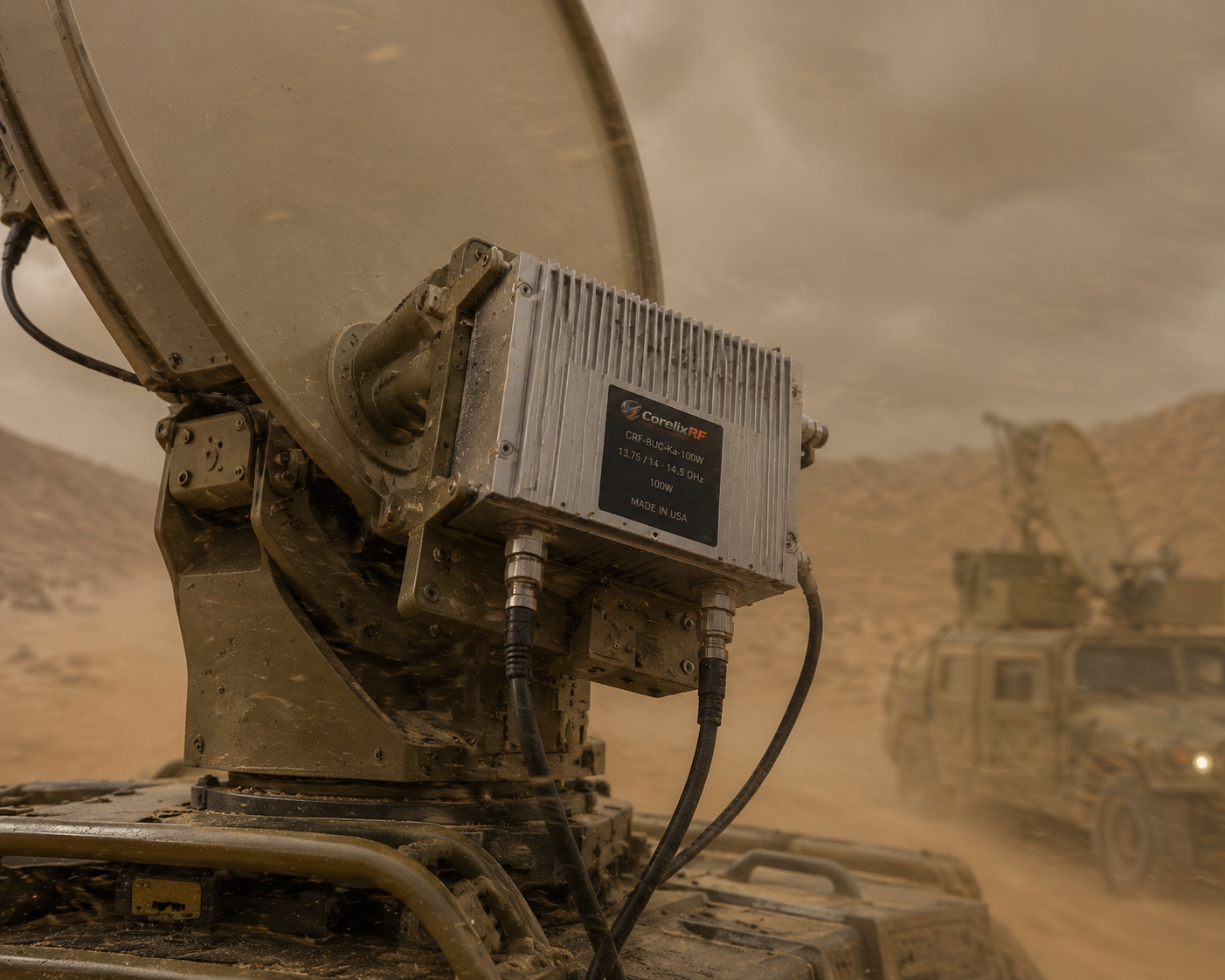
A massive electronic warfare shelter activates its primary jamming array. Sudden system resets occur instantly. This fault originates from high-current return paths shifting logic ground planes, causing critical control pins inside your block upconverter interpreting noise as actual trigger commands. We have observed this exact failure mode repeatedly over twenty years of field diagnostics. Our engineering team designed CorelixRF CRF-BUC-Ku-100W directly addressing such brutal grounding discrepancies. Using robust 48V architectures alongside specialized isolation boundaries establishes unparalleled operational reliability for defense integrators. Here is what matters most… resolving these parasitic loops requires fundamental architectural changes rather than simple software patches.
1. Why Do Large Electronic Warfare Shelters Experience Weak-Signal False Triggers During High-Power Transmission?
● Identifying Chassis Ground Inductance Limitations
● Analyzing High-Current Ramp-Up Profiles
● Resolving Shielded Cable Vulnerabilities
Electronic warfare platforms pack numerous high-power amplifiers into confined metal structures. When a Ku-band array transitions from standby mode into full transmission, sudden power demands draw hundreds of amperes across shared chassis grounds. This massive current flow encounters parasitic inductance along metal panels. A temporary voltage differential forms between different grounding points. Control interfaces operating on standard TTL or LVDS levels suddenly reference a ground plane floating several volts higher than normal. You might be wondering why do shielded cables fail under these exact conditions? Shielding prevents radiated emissions but cannot fix conducted loops formed when terminating both ends directly onto disparate ground potentials. The resulting voltage spike registers as an active high signal upon logic pins. System controllers read these phantom pulses, initiating emergency shutdowns or erratic frequency hopping. Fixing such structural flaws requires precise hardware selection at your RF front-end. Our approach demands components designed specifically expecting severe voltage transients. Engineers must stop treating metal enclosures as perfect zero-ohm conductors. Real-world physics dictates that rapid current transitions generate counter-electromotive forces. Therefore, selecting an upconverter with properly isolated telemetry lines represents the only viable long-term solution.
Ground Bounce Impact on Logic Thresholds
| Logic Family | Nominal Voltage | Trigger Threshold | Susceptibility to 1.5V Ground Shift |
| TTL | 5.0V | 2.0V | High |
| LVCMOS | 3.3V | 1.5V | Critical |
| RS422 | Differential | 200mV | Moderate |
| CorelixRF Ethernet | Isolated | N/A | Immune |
2. How Does Grounding Fault High-Current Return Disrupt System Logic in Radar and EW Front-Ends?
● Calculating Return Path Resistance Voltage Drops
● Evaluating Vulnerable Communication Connectors
● Examining Component Failure Under Saturation
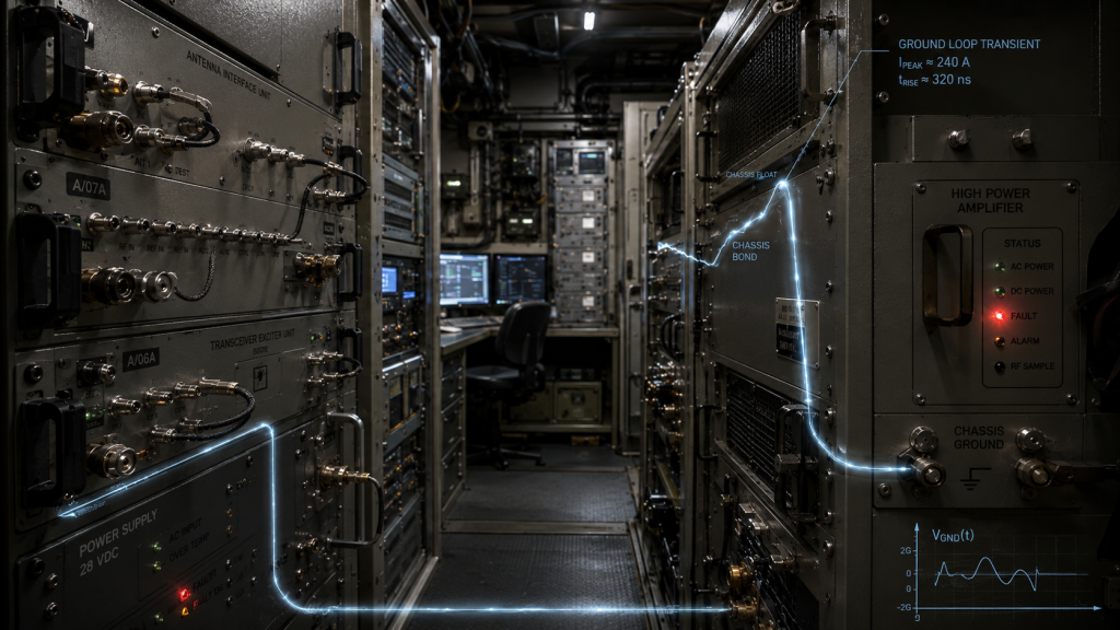
Let us examine fundamental physics driving this specific failure mechanism. An amplifier consuming 450 watts typical power, like our Ku-band units, pulls substantial current through direct current supply lines. If return paths lack sufficient cross-sectional area, resistance increases predictably. Ohms law dictates that high current multiplied by even milliohms of chassis resistance creates measurable voltage drops. Logic circuits utilizing 3.3V thresholds misinterpret a 1.5V ground bounce as a state change. The reality is engineers often overlook return path impedance during initial schematic reviews. They focus entirely upon forward RF propagation characteristics. When your transmitter hits 50 dBm saturated output power, return currents seek paths of least resistance. This current frequently travels through delicate Ethernet or monitoring cable shields. Ethernet communication interfaces using RJ45 connectors become vulnerable pathways for destructive currents. Isolating these monitoring methods requires physical decoupling internal to your block upconverter. Designing robust architectures means treating every ground pin as a potential noise injector. You must assume maximum current draw will occur instantaneously during pulse radar modes. Our architecture accounts for this by segregating heavy power grounds away from sensitive digital reference planes internally.
3. What Diagnostic Indicators Point Directly to Ground Loop Interference in Ku-Band Subsystems?
● Capturing Oscilloscope Differential Measurements
● Tracking Local Oscillator Modulation Artifacts
● Identifying Phase Noise Degradation Signatures
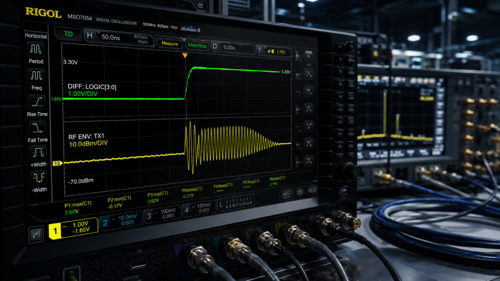
Field technicians constantly misdiagnose ground loops as software bugs. You must connect an oscilloscope featuring differential probes directly across your BUC power input and logic ground. During power ramp-up, watch that baseline voltage carefully. A sharp spike correlating exactly with RF envelope expansion confirms return path inductance issues. It gets worse spectrum analyzers connected via test ports might show elevated noise floors spreading across your entire 13.75 GHz spectrum. This happens because low-frequency ground oscillations modulate your local oscillator directly. Our equipment utilizes a 12.8 GHz or 13.05 GHz LO frequency, requiring exceptional stability. If ground faults inject noise into your 10 MHz reference input, phase noise degrades severely. You will see close-in phase noise failing our strict ≤-65 dBc/Hz at 100Hz specification. Identifying these specific waveform distortions allows engineers to stop replacing functioning components blindly. You must address actual grounding architecture flaws instead. Proper diagnostics save weeks of wasted troubleshooting time. When you observe symmetrical sidebands appearing around your main carrier, immediately suspect power supply return instability rather than complex internal synthesizer failures.
Diagnostic Signatures of Ground Loop Faults
| Diagnostic Tool | Measurement Location | Fault Signature Observed |
| Oscilloscope | Logic Ground Pin | Millivolt spikes synchronous with RF pulses |
| Spectrum Analyzer | Output Test Port | Elevated wideband noise floor |
| Phase Noise Tester | RF Output | Degradation below 1KHz offsets |
| Multimeter | Chassis Chassis | Milliohm resistance variance between panels |
4. How Does the CRF-BUC-Ku-100W Power Architecture Mitigate Chassis Ground Transients?
● Implementing Robust 48V Power Schemes
● Establishing Galvanic Isolation Boundaries
● Filtering Incoming Supply Line Anomalies
CorelixRF engineered the CRF-BUC-Ku-100W specifically anticipating hostile electrical environments found within mobile shelters. We implemented a robust 48V (36 – 72 V) supply voltage scheme. Higher voltage naturally reduces required current for any given 450W power consumption. This directly cuts return path voltage drops significantly. But here is the kicker we incorporate complete galvanic isolation between primary power returns and communication logic grounds. Our three-pin aviation connector handles bulk power delivery safely. This keeps heavy currents isolated from sensitive RJ45 Ethernet monitoring ports. By severing direct metallic connections linking these domains, ground loops cannot form through network switches. Furthermore, internal regulators filter incoming DC lines against severe transients before feeding RF stages. This methodology ensures continuous operation even when shelter generators output heavily distorted power waveforms. We designed an optional AC220V ±15% configuration serving ground VSAT stations lacking dedicated DC buses. Our internal DC-DC converters utilize planar transformers offering high isolation breakdown voltage ratings. This guarantees complete separation protecting downstream routing hardware against catastrophic shelter power surges.
5. What Are the RF Performance Advantages of Deploying the CRF-BUC-Ku-100W in High-Density Shelters?
● Maintaining Spectral Cleanliness via IM3 Control
● Integrating Receive Rejection Filtering Internally
● Managing Gain Stability Across Extreme Temperatures
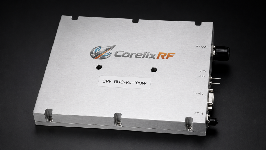
Deploying multiple transmitters demands strict adherence regarding intermodulation and spurious emissions. Our CRF-BUC-Ku-100W provides a rated output power of 50 dBm (100 W) while maintaining exceptional linearity. We guarantee IM3 levels ≤-25 dBc at 3 dB rated power back-off. What does this mean for you? It means your electronic attack signals remain spectrally clean. This avoids unintended interference with adjacent friendly receivers operating nearby. We also integrated advanced receive rejection filtering directly inside our 225 × 151 × 141 mm package. This prevents powerful transmission signals from leaking back into delicate receiving chains. With small signal gain exceeding 68 dB and wide gain adjustment ranges spanning 20 dB via 0.5 dB steps, system integrators gain precise control over link budgets. These parameters remain rock solid. We maintain ±2 dB stability across the entire operating temperature range. Squeezing this much RF performance into a 5.5 kg footprint requires specialized microwave substrate materials. We utilize advanced ceramic composites offering low dielectric loss at 14.5 GHz, ensuring maximum power transfers from transistor packages directly into your waveguide transition.
CRF-BUC-Ku-100W RF Characteristics vs Operational Benefit
| Metric | CorelixRF Specification | System Integration Impact |
| RF Frequency | 13.75 / 14 – 14.5 GHz | Covers standard and extended Ku-band allocations |
| Saturated Output | ≥50 dBm | Ensures adequate margin for complex waveforms |
| Gain Flatness | ±2 dB / 750 MHz | Maintains signal fidelity across wide bandwidths |
| Spurious Emissions| ≤-55 dBc | Prevents desensitization of co-located receivers |
6. How Do Built-in High-Power Isolators Protect the CorelixRF Block Upconverter Under Severe Mismatches?
● Understanding Antenna Degradation Mechanisms
● Absorbing Reflected Microwave Energy Safely
● Eliminating Reliance Upon Software Shutdown Routines
Antenna systems mounted atop moving vehicles frequently suffer damage. Connectors loosen, cables degrade, and radomes collect moisture over time. These physical changes alter antenna impedance violently. This sends massive amounts of reflected energy back toward your amplifier. This is where it gets interesting we integrated a high-power isolator directly at our WR75 output flange. When an antenna fails, creating high Voltage Standing Wave Ratios (VSWR), this isolator absorbs reflected RF energy. It turns that microwave power into heat safely. Your amplifier stages never see this destructive reflection. Our datasheets specify an output VSWR tolerance of 1.35:1 under normal conditions. However, built-in protection mechanisms prevent catastrophic transistor failure during sudden shorts or open circuits. This hardware-level defense eliminates reliance upon slow software-based shutdown routines. It saves expensive gallium nitride transistors from instant vaporization. Ferrite circulators utilized inside our isolators handle continuous mismatch conditions without saturating magnetically. We tested these components rigorously simulating severed waveguide runs under maximum 100W drive levels, proving our thermal routing effectively dissipates reflected loads indefinitely.
7. Why Is IP65 and Thermal Design Critical for Maritime and Vehicle-Mounted VSAT Stations?
● Maximizing Convective Heat Transfer Surfaces
● Sealing Interfaces Against Salt Spray Corrosives
● Preventing Internal Condensation in Fluctuating Climates
Heat represents the primary enemy attacking RF electronics constantly. Producing 100 watts of Ku-band energy generates substantial thermal waste naturally. If you examine our mechanical outline closely, you will notice extensive finning machined directly into our aluminum chassis. We designed this 5.5 kg package maximizing surface area for optimal air cooling. Let us dig deeper maritime environments introduce corrosive salt spray heavily. Vehicle deployments involve fine dust ingress continually. Our IP65 rating guarantees complete protection against dust and low-pressure water jets. We seal every single interface, including the N-F input and WR75 output flanges. We utilize aerospace-grade conductive gaskets preventing leakage. The unit operates flawlessly between -40 and 60 degrees Celsius environments. By managing thermal dissipation effectively without compromising environmental seals, we eliminate internal condensation issues. These moisture problems typically plague poorly designed commercial upconverters operating across fluctuating humidity zones. Dual integrated cooling fans provide forced airflow across deep heat sink channels. These fans feature conformal coated stators preventing moisture degradation, ensuring continuous CFM delivery even during torrential downpours or desert sandstorms.
Environmental and Mechanical Specifications
| Feature | CorelixRF Specification | Field Application Advantage |
| Operating Temp | -40°C to 60°C | Enables arctic and desert deployment |
| IP Rating | IP65 | Protects against dust and water spray |
| Weight | 5.5 kg | Reduces payload mass on mobile antennas |
| Cooling Method | Forced Air Cooling | Maintains transistor junction temperatures safely |
8. How Does Phase Noise and Spurious Suppression Maintain EW Targeting Integrity?
● Achieving Ultra-Low Jitter in Frequency Synthesis
● Shielding Digital Noise from Microwave Substrates
● Controlling Transmit In-Band Noise Floors
Electronic warfare effectiveness relies upon precise frequency synthesis fundamentally. Target tracking algorithms fail rapidly if your transmission signal contains excessive jitter. Our CRF-BUC-Ku-100W accepts standard 10 MHz reference signals via its IF port. Internal phase-locked loop multipliers achieve ultra-low phase noise profiles easily. We specify ≤-75 dBc/Hz at 1KHz and ≤-85 dBc/Hz at 10KHz offsets. Here is the secret achieving these numbers requires meticulous layout designs. We isolate noisy digital circuits away from sensitive microwave substrates using thick metal shielding walls. Furthermore, transmit and receive in-band noise remains strictly controlled internally. It registers below -76 dBm/Hz consistently. This prevents our transmission chain from raising noise floors inside your shelter. Strict spurious suppression below -55 dBc guarantees jamming energy concentrates entirely upon intended frequencies. This maximizes operational ranges while minimizing fratricide against allied communications networks. We filter every supply rail feeding our voltage-controlled oscillators aggressively. This eliminates microphonic responses induced by heavy vehicle vibrations, maintaining spectral purity even while driving across rugged off-road terrain profiles.
9. What Communication Interface Strategies Prevent False Alarms in Networked RF Arrays?
● Utilizing Differential Signaling Transformers
● Implementing Packet-Based Checksum Validation
● Replacing Analog Triggers with Digital Telemetry
Modern EW shelters network dozens of amplifiers together simultaneously. Engineers require real-time telemetry detailing temperature, current, and output power constantly. Using legacy serial protocols over unshielded wires invites disaster. Routing these cables near 100W microwave sources creates massive interference problems. Our CorelixRF monitoring method utilizes Ethernet routed through ruggedized aviation RJ45 connectors. You need to know this Ethernet inherently utilizes differential signaling via isolation transformers located inside physical layer chips. This magnetic coupling blocks common-mode voltage shifts caused by high-current ground faults entirely. Internal firmware features robust alarm and protection functions tailored for temperature monitoring. Instead of relying upon analog voltage triggers, we send digital packets carrying checksums. A ground bounce cannot alter a checksum without invalidating that entire packet. This prevents false alarms from ever reaching your central control terminal. Network switches simply discard corrupted packets, requesting retransmission automatically. This architecture provides complete immunity against electromagnetic pulses generated during high-power array switching events, keeping command centers free from ghost errors.
Telemetry and Control Interface Security
| Interface Aspect | CorelixRF Implementation | Ground Loop Mitigation |
| Physical Layer | Ruggedized Aviation RJ45 | Shielded shell with secure locking |
| Electrical Layer | Transformer Isolated Ethernet | Blocks common-mode voltage spikes |
| Data Link Layer | Packet Checksums | Invalidates noise-corrupted telemetry |
| Monitoring Method | Digital Polling | Replaces voltage-sensitive analog lines |
10. How Should Engineers Execute Final System Integration Using the CRF-BUC-Ku-100W?
● Securing Mechanical Mounting for Vibration Resistance
● Verifying Isolated Power and Ground Connections
● Validating RF Output and Telemetry Performance
Executing successful integrations demands rigorous testing methodologies. Begin by mounting our 225 × 151 × 141 mm chassis securely. Use designated M4 and M5 threaded holes shown on our mechanical outline. Ensure bare metal contact exists between BUC grounding lugs and shelter chassis panels. Supply 48V power using heavy-gauge wire minimizing voltage drops strictly. Now pay attention inject your 950 MHz – 1450 MHz IF signal keeping input levels monitored tightly. Utilize high-quality N-type connectors torqued properly. Connect WR75 waveguides using appropriate sealing gaskets preventing RF leakage. Before enabling transmission, verify Ethernet telemetry reports normal idle currents accurately. Ramp up power gradually while observing spectrum analyzers constantly. Ensure no unexpected spurious signals emerge due to local waveguide mismatches. CorelixRF supplies test data and pattern files for project reviews regularly. This accelerates validation phases significantly. Always wrap external RF connections with self-amalgamating tape preventing moisture intrusion over time. Proper torqueing of WR75 flange bolts ensures optimal return loss, maximizing efficiency for your completed electronic warfare system.
Final System Recommendations
Addressing false logic triggers inside dense electronic warfare shelters requires adopting isolated, high-voltage hardware architectures over vulnerable legacy designs. Integrating CorelixRF CRF-BUC-Ku-100W eliminates ground loop interference completely through physical isolation, robust thermal management, and superior RF component selection. Stop battling phantom alarms generated by inadequate return paths today. Contact our technical team immediately requesting detailed 3D models and compliance testing reports.
Q1: What is the CorelixRF CRF-BUC-Ku-100W?
The CRF-BUC-Ku-100W operates as a high-performance block upconverter delivering 100 watts of Ku-band RF power, designed specifically for rigorous defense and satellite communication environments requiring extreme reliability.
Q2: How does the built-in high-power isolator work?
This internal component absorbs reflected microwave energy caused by antenna mismatch, dissipating it harmlessly as heat rather than allowing that energy to destroy sensitive internal amplifier stages.
Q3: Why do ground loops cause logic failures in RF systems?
High current draw from amplifiers creates voltage drops across resistive chassis connections, shifting the ground reference potential and causing logic pins to register false high signals.
Q4: What communication interfaces are available on this model?
This unit utilizes a ruggedized RJ45 aviation connector providing isolated Ethernet monitoring, ensuring telemetry remains protected against electrical noise and ground voltage fluctuations.
Q5: How does IP65 sealing benefit vehicle-mounted stations?
IP65 certification guarantees the enclosure remains completely impervious against dust ingress and low-pressure water streams, preventing internal corrosion and condensation failures during mobile field deployments.
Make the lab setup and report curves part of the RFQ
Test-bench issues become easier to resolve when the RFQ lists signal source, cable loss, load condition, calibration setup, power sequencing, gain flatness, spurious limits and report format.
Recommended next step: send the operating band, output power target, duty cycle, load condition, control interface, protection or thermal limits and required FAT documents. CorelixRF can review this How to Prevent RF Front-End Ground Loops During 100W Transmission? requirement against standard RF amplifier platforms, RF front-end options and controlled customization paths.