
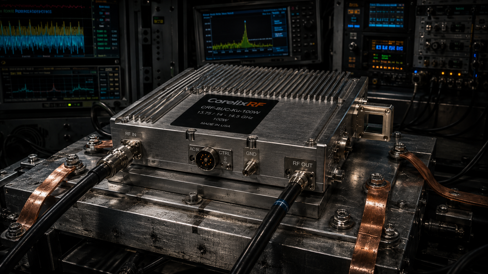
Large electronic warfare shelters face severe grounding faults when heavy RF returns disrupt logic pins. Our engineering team presents practical hardware solutions addressing false triggering mechanisms within complex field operations. CorelixRF delivers ruggedized architecture preventing catastrophic mission failures during intense electromagnetic interference scenarios.
1. What Triggers False Alarms in Large Electronic Warfare Shelters?
● Grounding loop fundamentals
● High-current return paths
● Weak-signal pin vulnerability
Here is the deal, false alarms within high-power military shelters originate from fundamental physical layout flaws. Operators often ignore how massive chassis metal behaves during high-frequency operation. Return currents from massive transmitters seek paths of least resistance. These paths unexpectedly cross weak-signal control lines. Microcontrollers misinterpret millivolt fluctuations as legitimate commands. A 100W transmitter pulling hundreds of watts creates substantial voltage drops across imperfect ground planes. We see this daily when field technicians report random VSWR faults. The shelter environment features immense vibration and extreme temperature shifts. Connectors loosen slightly over months of deployment. Contact resistance increases dramatically across these degraded mechanical joints. Heavy current flowing through these resistive joints elevates local ground potentials. Logic low signals suddenly register as logic high. Defense contractors waste weeks blaming firmware bugs. Real physics dictates that copper plains cannot sink infinite current instantly without voltage gradients. We measure these gradients using high-bandwidth differential probes. System integrators must map every single return path meticulously.
Grounding Flaw Characteristics | Impact Level | Diagnostic Method
Loose Chassis Fasteners | Severe | Micro-ohm meter testing
Shared Return Paths | High | Differential oscilloscope probing
Corroded Mating Surfaces | Critical | Visual inspection and VNA drops
2. How Does Poor Grounding Impact High-Power RF Systems?
● Voltage potential differences
● Chassis grounding failures
● Signal degradation mechanics
You might be wondering, how exactly do voltage potential differences tear down expensive RF chains? Large EW shelters pack multiple kW-level transmitters into tight, unyielding racks. A single poor weld on a chassis rail introduces milliohms of parasitic resistance. When our 48V power supply drives 450W into an amplifier, 10 amps rush back through that rack. Ten amps across ten milliohms equals one hundred millivolts of ground bounce. Standard TTL logic thresholds barely tolerate such aggressive bouncing. An active low mute pin might float above its trip point. This floating state disables transmitters randomly during active jamming missions. Signal degradation mechanics follow similar destructive patterns. Stray RF couples into poorly terminated shields. Our engineers frequently find generic commercial cables acting as parasitic antennas. These cables pick up high-power Ku-band energy directly. Reflected energy destroys sensitive upconverter mixer stages. Real-world engineering requires redundant, oversized grounding straps bolted directly onto bare metal. We mandate removing paint layers under every single equipment ear.
3. Why Do Heavy Return Currents Cause Logic Level Shifts?
● Ohmic loss across ground
● Transient current spikes
● Control circuit misinterpretations
What is the catch, when integrating commercial off-the-shelf components inside military vehicles? Transmitters undergo violent power cycling sequences. Sudden current demands create massive magnetic field variations. Inductive kicks travel along shared ground planes. Control circuit misinterpretations happen because these spikes exceed noise margins. Optoisolators become mandatory for any data communication crossing distinct power zones. We analyze failed modules returned from field deployments. Most show burnt logic gate inputs rather than blown RF transistors. Ohmic loss across ground structures dictates survival rates. A thin copper trace cannot handle pulsed currents generated by radar sweeps. Voltage references shift dynamically under heavy loads. Sensors reading thermal data output garbage values. The main processing unit reads these anomalies. It then triggers false over-temperature shutdowns. Operators lose transmission capability exactly when they need peak power. Proper architecture demands totally separate analog, logic, and power return layers. Star grounding topologies prevent these transient current spikes from migrating into weak-signal domains.
Failure Mode | Root Cause | Engineering Solution
Logic Gate Burnout | Inductive Kickback | Opto-isolated inputs
False Thermal Alarm | Reference Voltage Shift | Star grounding topology
Random Muting | Ground Bounce | Separate return layers
4. What Are Common BOM Selection Traps for Shelter Integrators?
● Inadequate isolation ratings
● Substandard connector choices
● Filter bypass issues
Consider this reality, specifically examining typical bill of materials failures. Procurement departments frequently substitute specified connectors with cheaper alternatives. Substandard connector choices ruin robust system architectures instantly. An aviation-grade three-pin connector handles severe vibration without losing contact pressure. Commercial RJ45 jacks vibrate loose inside diesel-powered shelters. This intermittent contact creates havoc on Ethernet monitoring streams. Filter bypass issues represent another massive trap. Engineers place excellent EMI filters near power entries. They then route noisy unshielded cables right past those filters. High-frequency noise jumps across the physical gap via capacitive coupling. The expensive filter becomes totally useless. Inadequate isolation ratings on DC-DC converters also plague large installations. When a 100W amplifier powers up, primary voltage sags. Cheap converters drop out, resetting internal microprocessors. We build our equipment utilizing components rated for harsh environments. Every interface requires rigorous review against expected electrical abuse. Our technical teams reject BOMs containing marginal components immediately. Engineering truth leaves no room for budgeting compromises on critical interconnects.
5. How Can Hardware Architecture Prevent Ground Loop Interference?
● Single-point vs multi-point ground
● Optocoupler isolation strategies
● Physical layout separation
This is where it gets interesting, separating noisy circuits from quiet ones requires ruthless physical discipline. Multi-point grounding works well for purely RF signals. It provides low-impedance paths for high-frequency return currents. However, DC power returns must employ strict single-point topologies. Mixing these philosophies guarantees disaster inside an EW shelter. Optocoupler isolation strategies break galvanic connections completely. We place optical boundaries between our Ethernet control lines and main processing cores. A massive ground fault elsewhere cannot push current backwards into our communication interfaces. Physical layout separation acts as the ultimate barrier. We physically distance power supply modules from sensitive IF input stages. The CRF-BUC-Ku-100W receives a 950 MHz input signal at 0 dBm. A tiny amount of coupled noise would degrade phase noise performance drastically. By carving slots in PCB ground planes, we force currents around sensitive zones. This routing strategy requires complex 3D electromagnetic simulations during the design phase. We validate these models thoroughly on actual vibration tables.
Routing Strategy | Signal Type | Grounding Topology
RF Chains | High Frequency | Multi-point grounding
DC Power | High Current | Single-point star ground
Ethernet Control | Weak Signal | Optically isolated floating ground
6. What Makes the CRF-BUC-Ku-100W Suitable for Harsh Electromagnetic Environments?
● Internal isolation design
● Power interface specifications
● Alarm protection logic
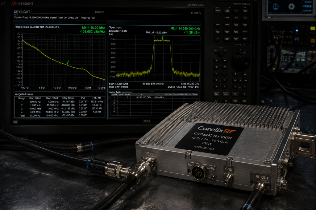
Look closely at the data, examining specific hardware reveals true ruggedness. The CRF-BUC-Ku-100W operates reliably between 13.75 GHz and 14.5 GHz. We designed an internal architecture centered around absolute isolation. A built-in high-power isolator protects the final amplifier stage from infinite VSWR events. When antennas get damaged by shrapnel, reflected power hits this isolator instead of fragile transistors. Our power interface specifications demand a robust 48V supply via a secure aviation connector. This configuration withstands intense physical shocks. Alarm protection logic constantly monitors internal temperature and current consumption. Unlike fragile commercial units, our firmware demands multiple sequential out-of-bounds readings before triggering a shutdown. This hysteresis prevents transient noise from causing false alarms. The IP65 rated enclosure stops salt fog and conductive dust penetration. We built this 100W block upconverter specifically for vehicle and maritime satellite communications. It delivers greater than 50 dBm saturated output power under brutal conditions. Field reliability stems directly from anticipating electromagnetic chaos.
7. How Does CorelixRF Mitigate Spurious Signals in Ku-Band Operations?
● Integrated receive rejection
● Ultra-low phase noise
● Harmonics suppression techniques
Ready for the good part?, maintaining spectral purity demands extraordinary filtering techniques. Spurious emissions from a 100W amplifier will blind friendly receivers nearby. We implement integrated receive rejection filtering directly behind the output waveguide. This suppresses transmit noise below -156 dBm/Hz in the 10.95 – 12.75 GHz receive band. Such deep rejection prevents receiver desensitization. Ultra-low phase noise oscillators form the heart of our frequency conversion blocks. Our 10 MHz reference input generates LO frequencies with exceptional stability. We achieve phase noise better than -95 dBc/Hz at 100 KHz offset. This clarity supports high-order modulation schemes required for modern tactical datalinks. Harmonics suppression techniques involve carefully tuned matching networks. We do not rely solely on bulky external cavity filters. Our engineers optimize drain bias networks, preventing harmonic generation at its source. A clean spectrum output guarantees full energy hits the intended target frequency. Anything less wastes DC power and creates fratricide amongst co-located radio equipment.
RF Performance Metric | Specification Limit | Operational Benefit
Transmit Noise Floor | $\le$ -156 dBm/Hz | Prevents receiver blinding
Phase Noise | $\le$ -95 dBc/Hz @ 100KHz | Enables high-order modulation
Harmonic Suppression | Integrated Bias Tuning | Eliminates fratricide
8. Why Does Thermal Dissipation Affect Grounding Integrity Over Time?
● Thermal expansion shifting
● Material degradation impacts
● Heat sink mounting impedance
Now, pay attention, thermodynamics directly influence electromagnetic compatibility. A 450W power consumption profile generates massive heat loads. We specify operating temperatures from -40 to 60 degrees Celsius. As metal chassis components heat up, they expand at different rates. Aluminum enclosures rub against steel mounting racks. This thermal expansion shifting breaks brittle oxide layers. It causes micro-arcing during high-vibration events. Such arcing injects broadband noise straight into the grounding system. Material degradation impacts thermal interface materials severely. Cheap thermal pastes dry out, pumping out from beneath hot power transistors. As components overheat, their internal leakage currents rise exponentially. Heat sink mounting impedance changes drastically over a few months. Engineers must use specialized conductive gaskets maintaining constant pressure. We bolt our heavy 5.5 kg modules utilizing locking washers and thread-locking compounds. These mechanical precautions guarantee stable ground impedance regardless of thermal cycling. Electronic warfare systems fail when mechanical details get ignored during prototyping.
9. How Can Field Engineers Diagnose Grounding Faults Using Oscilloscopes?
● Probing differential noise
● Identifying transient peaks
● Analyzing control line stability
Let’s be clear, guessing wastes valuable deployment time. Field engineers must approach these issues methodically using proper instrumentation. Probing differential noise requires isolating the oscilloscope from AC mains ground. Standard single-ended probes simply inject more noise into floating grounds. Technicians must clip differential probes across suspected weak-signal pins and their local reference points. Triggering on logic level transitions reveals the exact moment interference occurs. Identifying transient peaks demands high sampling rates. We recommend capturing waveforms during transmitter pulse-on events. This specific window contains the largest magnetic field variations. Analyzing control line stability involves watching for voltage droop during sustained transmission. If an active high enable signal dips below 3.3V, a ground loop is stealing current. I have spent decades teaching technicians how to read these specific noise signatures. Proper diagnosis prevents unnecessary component swapping. A 100W Ku-band BUC rarely fails spontaneously; bad shelter wiring usually murders it. Fixing the root cause guarantees long-term operational success.
10. What Are Effective Integration Practices for 100W Block Upconverters?
● Power supply dimensioning
● Waveguide mating protocols
● Ethernet monitoring setup
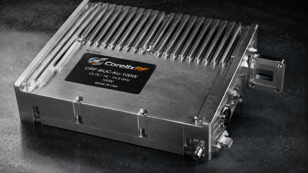
It boils down to this, successful integration requires rigorous adherence to documented procedures. Power supply dimensioning must account for peak current demands. A BUC drawing 450W nominally might pull significantly more during startup transients. We advise sizing power plants with at least thirty percent headroom. The 48V supply lines require heavy gauge wire minimizing voltage drops. Waveguide mating protocols demand absolute cleanliness. A single spec of dust on a WR75 flange degrades the 1.35:1 VSWR specification. Technicians must inspect every surface, using proper torque sequences on all bolts. Ethernet monitoring setup involves configuring RJ45 connections correctly. The shelter network switch must handle UDP packets efficiently. Our equipment reports internal temperature and gain adjustments seamlessly via this interface. Routing Ethernet cables away from high-power RF lines prevents data corruption. Shielded twisted pair cabling remains non-negotiable in these environments. We built the CorelixRF equipment rugged, but smart installation realizes its full combat potential.
Integration Checklist | Required Action | Consequence of Failure
Power Plant Sizing | Add 30% Headroom | Startup voltage dropouts
Waveguide Flanges | Clean and Torque | Degraded VSWR performance
Ethernet Routing | Separate from RF cables | Packet corruption
Systematic grounding failures within electronic warfare shelters destroy operational readiness. Implementing rigorous physical isolation and deploying hardened RF hardware eliminates these disastrous logic faults. The CRF-BUC-Ku-100W provides a heavily protected, high-power foundation for serious defense integrators. Contact our engineering team today for comprehensive datasheet access and advanced system-level evaluation support.
Q1: What is the frequency range of the CRF-BUC-Ku-100W?
The frequency range spans from 13.75 GHz to 14.5 GHz, providing excellent Ku-band coverage for high-power transmission.
Q2: How does the built-in isolator work?
It absorbs reflected RF energy when extreme VSWR events occur, protecting the sensitive internal power amplifier transistors.
Q3: What causes false thermal alarms in these systems?
Heavy return currents shift ground reference voltages, causing sensor readouts to spike artificially and trigger shutdown protocols.
Q4: Why is differential probing required for field diagnostics?
Standard probes introduce additional ground loops, whereas differential probes measure the exact potential difference across specific components.
Q5: What power supply does this 100W BUC require?
It requires a stable 48V DC supply, accepting inputs between 36V and 72V, consuming 450W typically.
Authorized RF engineering and compliance review
For regulated RF systems, this page should be used as an engineering and compliance review path, not as a public deployment checklist. CorelixRF starts with authorization status, operating region, frequency plan, output limit, antenna interface, safety controls, thermal limits and acceptance documents.
- RFQ checklist – send the data buyers usually forget, including band, power, duty cycle, interface and test standard
- delivery documentation – check what documents can support incoming inspection, FAT review and long-term maintenance
- quality and certification review – review the quality and compliance evidence before the project moves into procurement
- RF front-end platform – compare the RF chain as a system instead of selecting one isolated module
- RF configurator – turn frequency, power, thermal and interface requirements into a first configuration brief
- case studies – review similar engineering paths before sending an RFQ
- engineering contact – send the application notes, block diagram or target specification to engineering sales
This keeps the discussion inside lawful, authorized RF programs while still giving procurement teams a clear way to request amplifier, antenna, SDR source, documentation and factory review.