
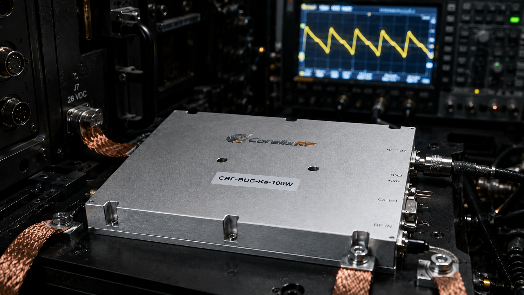
Troubleshooting EW Shelters: Grounding Faults And False Triggers. System lockups plague field engineers running high-power tactical arrays constantly. A sudden amplifier shutdown leaves radar networks completely blind. Thirty seconds of silence ruins your defensive posture permanently. We offer an effective method for isolating these hardware faults. Many technicians blame software bugs when control pins misbehave. They swap logic boards without checking underlying physical layers. Here is the deal. High-current return paths routinely hijack vulnerable grounding networks during peak operation. We see erratic voltage spikes causing constant headaches on site. This guide explains physical mechanisms behind frustrating field failures directly. Our team relies upon strict engineering truth rather than guesswork. Rely upon our twenty years of RF factory production experience. Let us analyze actual hardware behavior inside tactical shelter deployments.
1. What Causes Signal Anomalies In Large EW Shelters?
Identifying baseline noise floors
Operators inside an EW shelter frequently encounter strange spectrum readings. Baseband noise floors suddenly elevate during heavy radar transmission cycles. You might suspect a blown driver stage or mismatched antenna. A standard spectrum analyzer often shows mysterious low-frequency hums constantly. You might be wondering. Why do these phantom signals appear only during specific missions? The answer usually points directly toward poor physical grounding architecture. Large shelters pack massive electrical loads into very confined spaces. Powering a Ku-band block upconverter requires significant direct current overhead. That 450W typical power consumption strains every internal connection point. Your baseline noise floor reflects the overall health of grounds. A healthy ground keeps your spectrum analyzer screen completely clear. We trace elevated noise directly back toward degraded physical connections.
Recognizing mechanical vibration effects
Heavy vehicle engines generate constant mechanical vibration during mobile operations. Constant shaking gradually loosens heavy-duty copper busbars over extended time. A loose busbar creates micro-arcing events within your equipment rack. Those tiny arcs generate wideband electromagnetic interference across entire bays. Sudden transmission bursts cause severe voltage sags across power rails. A 48V supply might temporarily drop significantly under heavy load. We use rapid-response oscilloscopes for capturing these transient voltage dips. Ground planes shift when main power rails struggle supplying current. This shifting ground reference heavily degrades phase noise performance predictably. Unstable grounds push phase noise readings into unacceptable operating ranges. We measure ≤-65 dBc/Hz at 100Hz offset under normal conditions. Mechanical vibration destroys that pristine phase noise measurement almost instantly. You must secure all power cables using industrial locking mechanisms.
Noise Source Identification
| Symptom | Primary Cause | Diagnostic Tool |
| Elevated Baseband | Ground Loop | Spectrum Analyzer |
| Wideband Spikes | Loose Busbar Arcing | High-Z Oscilloscope |
| Phase Noise Degradation | Voltage Sags | Phase Noise Tester |
2. How Do Poor Grounding Networks Impact System Reliability?
Analyzing high resistance chassis bonds
Engineers must recognize how grounding networks dictate overall system health. A faulty ground loop completely destroys delicate baseband signal integrity. We frequently inspect tactical vehicles displaying severe SWR alarm errors. The local technician usually assumes an antenna cable failed somewhere. What is the real story? Poorly bonded chassis panels create massive resistance paths for current. High-power RF modules dump excess heat and current into panels. If that chassis lacks solid earth bonding then trouble begins. The return current desperately seeks any available path toward sources. A poorly grounded panel vibrates constantly during rough terrain transport. This vibration wears down protective zinc coatings rapidly and continually. Bare steel oxidizes within hours under coastal salt fog conditions. You end up with invisible insulators hiding between frame components.
Tracking wandering return currents
This wandering current often travels through sensitive communication interface cables. An Ethernet RJ45 shield suddenly carries amps of unintended power. Those data cables melt or fail under such severe stress. You lose remote monitoring telemetry before realizing what happened entirely. The CRF-BUC-Ku-100W utilizes an aviation-grade RJ45 connector specifically for durability. A weak ground network renders even military-grade connectors totally useless. System reliability plummets when grounding paths act like heating elements. You must measure chassis bonding resistance using four-wire micro-ohm meters. Anything above a few milliohms warrants immediate corrective maintenance action. High currents destroy fragile silicon logic gates without any warning. We design strong hardware capable of surviving minor ground faults. A complete ground failure eventually overwhelms even our robust protections.
3. Why Do High-Current Return Paths Form In Shelter Operations?
Understanding parallel resistance paths
A typical shelter houses multiple high-power amplifiers firing simultaneously together. A single 100W rated BUC draws nearly ten amps continuously. Imagine five identical units engaging during a coordinated jamming sequence. You suddenly have fifty amps flowing through common ground planes. Let me explain. Current always takes the path of least electrical resistance automatically. Copper ground straps corrode quickly due to harsh environmental factors. Oxidation layers build up unseen beneath tight mounting bolts continuously. That oxidation adds significant resistance toward primary high-current return paths. The fifty amps cannot pass through corroded bolts effectively anymore. This massive energy must find an alternative route back quickly. Smaller sensor wires offer parallel paths with lower relative resistance. The current forces its way through delicate monitoring circuit boards.
Observing physical board damage
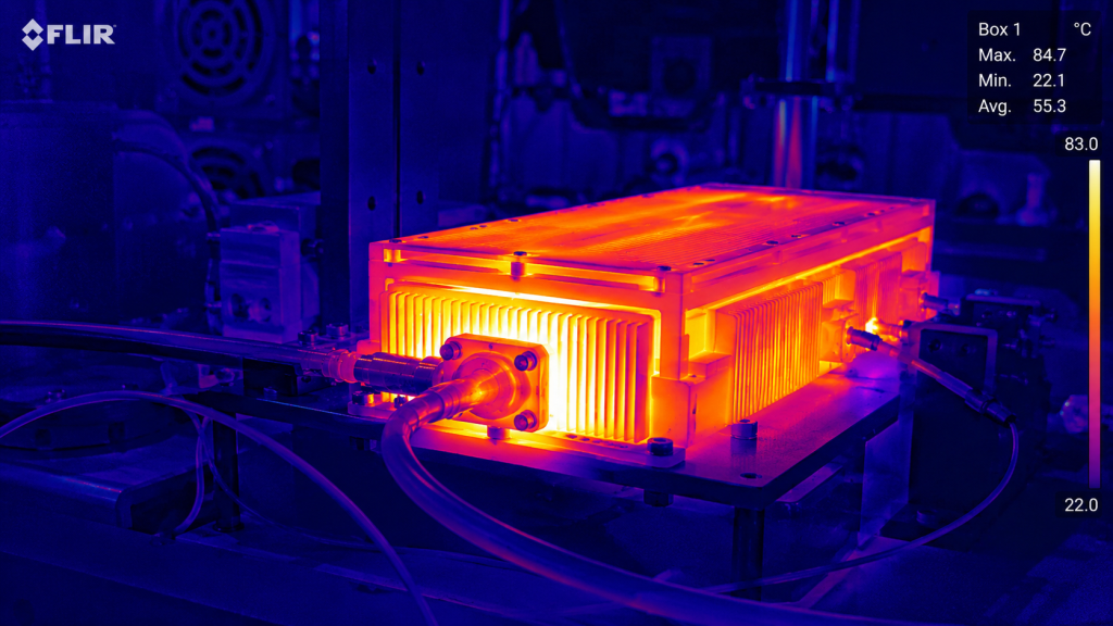
We observe similar destruction in older naval radar platforms regularly. A bad ground path turns your monitoring cables into fuses. Operators lose control over their arrays right during critical engagements. Replacing vaporized cables takes hours of agonizing manual labor typically. We see printed circuit board traces literally vaporizing under load. Your thermal monitoring circuits burn out within milliseconds of transmission. High-current paths form wherever maintenance crews neglect basic anti-corrosion practices. We recommend inspecting all grounding straps with thermal imaging cameras. Hot spots reveal hidden oxidation layers before catastrophic module failure. A hot ground strap indicates power turning into wasted heat. You lose output power when amplifiers fight against ground resistance. We build heavy copper traces inside our RF amplifier modules.
Resistance and Current Path Analysis
| Path Type | Expected Resistance | Failure Mode |
| Primary Copper Strap | < 5 milliohms | Salt Fog Oxidation |
| Secondary Chassis Bond | < 10 milliohms | Vibration Loosening |
| Sensor Wire Shield | > 50 ohms | Trace Vaporization |
4. What Triggers False Alarms On Weak-Signal Control Pins?
Examining ground bounce mechanisms
Control pins operate using very low voltage logic thresholds normally. A simple 3.3V signal tells an amplifier when to transmit. Ground bounce occurs when high return currents elevate local potentials. Your reference ground suddenly shifts two volts above true zero. This is where it gets interesting. The logic circuit misinterprets that voltage shift as an instruction. A false trigger commands your 50 dBm amplifier prematurely instantly. Firing an amplifier into an unmatched load destroys output stages. We build high-power isolators into our designs for this reason. That built-in isolator protects the RF chain from reflected energy. A false trigger still creates chaotic interference across communication networks. Weak-signal pins lack physical mass for handling transient current spikes. Stray RF energy also couples onto unshielded control wiring harnesses.
Mitigating stray RF coupling
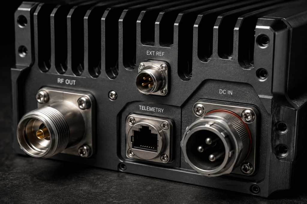
A 14 GHz transmission easily leaks into poorly designed enclosures. That leaked energy rectifies inside logic gates causing random reboots. We utilize heavily shielded three-pin aviation connectors for power interfaces. This isolation prevents stray current from triggering sensitive alarm circuits. A false trigger during maintenance could injure personnel working nearby. The 100W output generates hazardous field strengths within enclosed spaces. We design safety interlocks preventing uncommanded transmissions under single faults. Hardware must remain predictably safe despite severe external electrical noise. We filter every single input pin using feed-through capacitor networks. Those capacitors shunt high-frequency noise directly into the heavy chassis. You gain immunity against adjacent jammers operating nearby your shelter. False triggers disappear entirely once you isolate the logic grounds.
5. How Do We Isolate Ground Loops Using Diagnostic Equipment?
Deploying high speed oscilloscopes
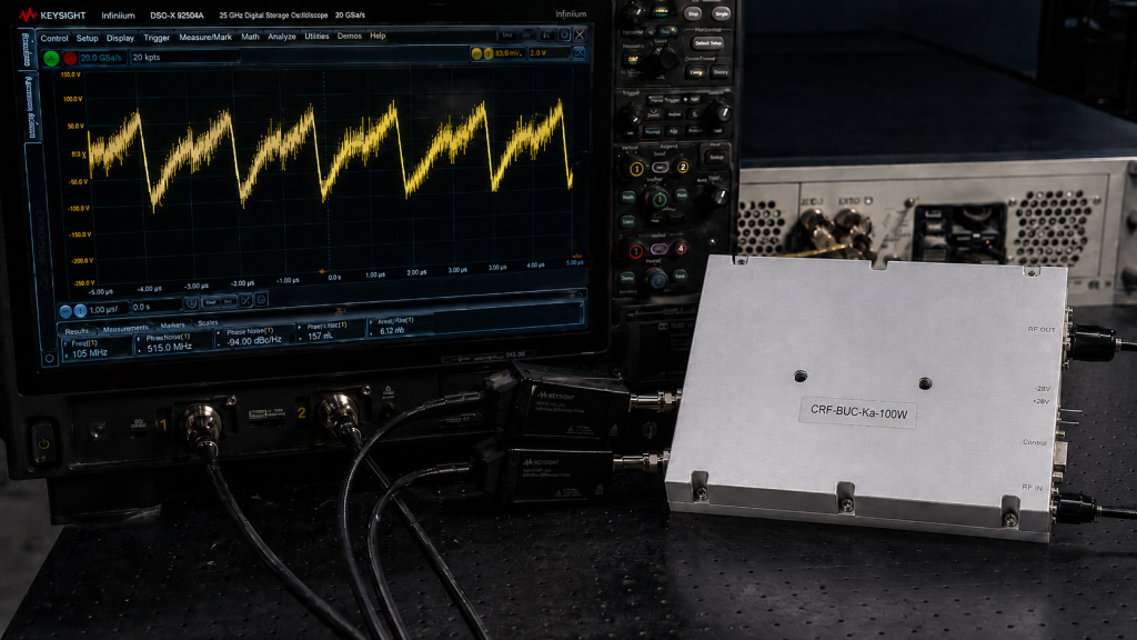
Field troubleshooting requires specific tools for identifying invisible electrical paths. You cannot fix ground loops using only a digital multimeter. A standard multimeter lacks sufficient bandwidth for seeing fast transients. Now pay attention. We deploy high-speed oscilloscopes equipped with differential active probes instead. Connect one probe across your main power supply output terminals. Connect another probe directly onto your module power input pins. Trigger your oscilloscope using an external transmission command pulse signal. Watch how voltage drops differ between those two measurement locations. A large discrepancy indicates massive resistance along your cabling run. You must also use directional couplers for measuring reflected power. A rising VSWR often correlates with worsening ground loop conditions. Return currents disrupt impedance matching networks within your antenna feed.
Documenting baseline resistance measurements
We look for VSWR readings exceeding a 1.5:1 ratio closely. Finding these loops requires patience and methodical point-to-point physical measurements. Disconnect non-essential equipment sequentially until noise floor readings drop significantly. This isolation process identifies exactly which component introduces rogue currents. Always document your baseline resistance values during initial shelter commissioning. Comparing future readings against this baseline highlights degrading physical bonds. Finding faults early prevents catastrophic amplifier damage during live operations. Solid diagnostic practices save thousands of dollars in replacement hardware. We provide factory test data showing optimal voltage drop profiles. You should compare your field readings against our factory benchmarks. A deviation exceeding ten percent warrants an immediate physical inspection. Your equipment rack acts as a massive interconnected RF ecosystem.
Diagnostic Tool Selection
| Tool Name | Measurement Target | Condition Indicated |
| Differential Probe | Voltage Transients | Ground Bounce |
| Directional Coupler | Reflected Power | Impedance Mismatch |
| Micro-Ohm Meter | Chassis Bonding | Interface Corrosion |
6. What Specific Oscilloscope Traces Reveal Ground Faults?
Analyzing sawtooth voltage patterns
Engineers must recognize distinct waveform signatures indicating severe grounding problems. A healthy power rail shows a clean horizontal line normally. Ground faults produce a characteristic sawtooth pattern during transmission bursts. Ready for the good part? This sawtooth waveform represents capacitors struggling against high path resistance. We also look for high-frequency ringing on rising pulse edges. Ringing indicates parasitic inductance within your main grounding strap connections. A 100W module pulls current far too fast for inductors. That inductive kickback generates voltage spikes exceeding sixty volts easily. Our hardware tolerates 36 to 72 volts input supply ranges. Cheaper modules lacking robust regulation catch fire from these spikes. An oscilloscope FFT function reveals exact frequencies of this ringing. You often see spikes aligning perfectly with clock generator frequencies.
Performing forensic failure analysis
These traces prove that digital noise bleeds into power domains. Capturing these traces requires setting trigger holds off correctly beforehand. We document every trace pattern for post-mission forensic failure analysis. Proper waveform analysis separates true engineering from blind parts swapping. We train our field teams for recognizing these exact traces. A fast Fourier transform isolates switching power supply noise efficiently. You can pinpoint which internal converter causes your ground bounce. Precision diagnostics prevent technicians from chasing phantom software bugs blindly. You stop replacing perfectly good computer boards wasting defense budgets. We built internal logging capabilities for capturing these transient events. Our Ethernet interface broadcasts alarm packets whenever voltage drops dangerously. You receive an exact timestamp detailing when the ground failed.
7. How Does The CRF-BUC-Ku-100W Mitigate These Grounding Risks?
Utilizing massive aluminum chassis
Our factory designs hardware specifically for hostile tactical operating environments. We engineered the CRF-BUC-Ku-100W utilizing an immensely thick aluminum chassis. This housing provides exceptional thermal mass and minimal electrical resistance. Here is the kicker. We completely separate internal RF grounds from digital logic grounds. A dedicated three-pin aviation connector handles bulk 48V power delivery. This connector design survives brutal physical shock and heavy vibration. We integrated an RJ45 aviation connector for Ethernet monitoring telemetry. This physical separation prevents bulk current from destroying sensitive communications. The module features active alarm protection for temperature and current. The system shuts down gracefully before ground loops cause fires. Heat acts as a major catalyst for electrical resistance increases. Our thick chassis dissipates 450W of heat load highly effectively.
Machining solid RF cavities
Keeping the module cool maintains stable resistance across internal bonds. You experience fewer thermal runaway events during extended transmission cycles. We achieve ≤-55 dBc spurious emissions through strict layout techniques. Our engineers machine RF cavities directly into solid metal blocks. This machining technique eliminates internal grounding wires completely reducing inductance. You get 50 dBm rated output power without stability concerns. This hardware reflects twenty years of brutal field testing reality. We do not rely upon thin stamped metal shielding anywhere. Every internal board mounts flush against heavy metal grounding posts. This direct mounting strategy provides zero impedance paths for current. Your RF signal remains pure despite chaotic external electrical storms. We provide mounting hole patterns optimized for maximum surface contact.
CRF-BUC-Ku-100W Mitigation Features
| Hardware Feature | Engineering Purpose | Grounding Benefit |
| Solid Aluminum Chassis | Thermal Mass | Low Resistance Path |
| Split Ground Planes | RF/Digital Isolation | Prevents Logic Bounce |
| Aviation Connectors | Vibration Resistance | Maintains Bond Integrity |
8. What Role Does Aviation-Grade Shielding Play In Shelter Deployments?
Defeating ambient microwave radiation
Commercial connectors fail rapidly inside military or heavy industrial shelters. A standard plastic Ethernet plug melts near high-power amplifier stages. We mandate aviation-grade shielding across all our external equipment interfaces. Listen to this. Metal connector shells provide a continuous Faraday cage around pins. This continuous metal barrier blocks external 14 GHz microwave radiation. Shielding stops high-frequency energy from coupling into internal baseband circuits. An unshielded wire acts like a perfect receiving antenna accidentally. It feeds jamming signals straight back into your own processors. Our IP65 rated enclosures keep corrosive salt fog out entirely. Preventing moisture ingress stops galvanic corrosion between different metal types. Clean metal contacts maintain the micro-ohm resistance levels required safely. Standard commercial interfaces invite disaster inside demanding tactical military environments.
Surviving severe mechanical shock
A single corroded pin drops your network connection permanently offline. Our shielded designs provide an uninterrupted mechanical defense against moisture. Equipment survival depends entirely upon these robust physical interface choices. We test these connectors under severe mechanical stress profiles continuously. The locking threads prevent backing out during prolonged transit routes. A secure thread guarantees your ground path remains absolutely solid. Aviation shielding represents basic survival gear for serious RF engineering. We supply mating connectors featuring heavy silver plating for conductivity. That silver plating resists tarnishing better than standard industrial nickel. You can tighten these connectors using standard field maintenance wrenches. The rugged housing prevents accidental damage from dropped heavy tools. We never compromise on external physical interfaces for B2B customers.
9. How Do We Validate Power Stability Under Extreme Load?
Pushing modules into saturation
Validating system stability requires testing hardware far beyond normal limits. We push amplifiers into deep saturation during our factory burn-in. The CRF-BUC-Ku-100W delivers 50 dBm under continuous wave test conditions. Truth be told. We monitor input voltage drops closely while drawing 450 watts. A simulated ground fault introduces intentional resistance into our setups. We measure how well internal regulators handle these starved conditions. The amplifier must maintain constant output power despite fluctuating supplies. We check IM3 distortion levels during these simulated voltage sags. Our specification demands ≤-25 dBc at 3 dB rated back-off. A poor ground causes IM3 performance to degrade almost immediately. We simulate worst-case voltage drops using programmable high-current DC loads. The amplifier must survive these torture tests without requiring reboots.
Relying upon empirical data
Our engineering process focuses heavily upon worst-case physical operating margins. We deliver reliable rf power across entirely unpredictable battlefields confidently. We use automated test racks for recording thousands of data points. This rigorous validation guarantees predictable behavior during actual combat scenarios. Field engineers rely upon our published data sheets for calculations. We never publish estimated specifications or theoretical performance curve graphs. You receive pure engineering truth backed by harsh empirical testing. We provide detailed test reports matching your exact serial number. Those reports prove our hardware handles unstable grounds without failing. You can trust our thermal cycling data under full load. We freeze modules at -40 degrees Celsius before applying power. The internal components survive immense thermal shock without cracking solders.
Power Stability Validation Metrics
| Parameter Tested | Test Condition | Pass/Fail Criteria |
| Rated Output Power | Continuous Wave | ≥ 50 dBm |
| IM3 Distortion | 3 dB Back-off | ≤ -25 dBc |
| Input Voltage Sag | +10% Path Resistance | No Auto-Shutdown |
10. Why Is Thermal And Current Monitoring Critical For RF Modules?
Tracking continuous current consumption
High-power RF modules generate extreme heat requiring constant active management. An amplifier drawing 450 watts turns most energy into heat. Ground loops exacerbate heating by adding resistance to return paths. Make no mistake. We implement continuous thermal and current monitoring via Ethernet connections. A sudden spike in current consumption usually precedes catastrophic failure. Field operators must receive these alarm packets without any delay. A melted logic pin destroys your ability for remote diagnostics. We designed our protection circuits for independent autonomous shutdown actions. The amplifier cuts power internally if temperature exceeds sixty degrees. This internal protection saves your investment when external systems fail. Monitoring lets technicians schedule proactive maintenance before actual hardware burns. You can track gradual resistance increases over months of deployment.
Utilizing actionable telemetry intelligence
Data logging provides actionable intelligence regarding your grounding network health. We build resilient nodes for surviving the harshest electromagnetic environments. We recommend integrating our telemetry data into your primary dashboards. Your software should flag any sudden current draw increases immediately. This proactive approach prevents unexpected downtime during high-stakes tactical deployments. Reliable RF generation demands continuous vigilance over physical electrical environments. An ignored current alarm always results in a melted board. We provide simple SNMP traps for easy software integration architectures. You do not need proprietary software for reading our telemetry. Open standards allow fast integration into existing military management networks. Our hardware reports its exact physical status without any obfuscation. We give engineers raw data required for making tactical decisions.
Engineers must treat physical grounding networks as critical system components. You cannot ignore high-current return paths inside complex tactical shelters. Our CRF-BUC-Ku-100W provides robust hardware isolation against severe transient voltage faults. Contact our factory team today for detailed schematic reviews. Secure your arrays using our proven industrial RF power solutions reliably.
FAQ
Q1: What is a ground loop in an RF system?
A ground loop occurs when multiple conductive paths exist between components, allowing stray high-current returns to cause interference.
Q2: How does the CRF-BUC-Ku-100W handle power fluctuations?
The module utilizes internal regulation to operate stably across a 36 to 72 volt input range despite supply sags.
Q3: Why do weak-signal pins experience false triggers?
Shifted ground potentials confuse logic circuits, causing them to interpret noise spikes as legitimate operational command voltages.
Q4: What tools detect high-current return path faults?
Engineers utilize high-speed oscilloscopes with differential probes and micro-ohm meters to measure chassis bonding resistance directly.
Q5: How does aviation shielding improve reliability?
Solid metal connector shells block ambient microwave radiation and prevent moisture ingress from corroding critical electrical contacts.
Authorized RF engineering and compliance review
For regulated RF systems, this page should be used as an engineering and compliance review path, not as a public deployment checklist. CorelixRF starts with authorization status, operating region, frequency plan, output limit, antenna interface, safety controls, thermal limits and acceptance documents.
- RFQ checklist – send the data buyers usually forget, including band, power, duty cycle, interface and test standard
- delivery documentation – check what documents can support incoming inspection, FAT review and long-term maintenance
- quality and certification review – review the quality and compliance evidence before the project moves into procurement
- RF front-end platform – compare the RF chain as a system instead of selecting one isolated module
- RF configurator – turn frequency, power, thermal and interface requirements into a first configuration brief
- case studies – review similar engineering paths before sending an RFQ
- engineering contact – send the application notes, block diagram or target specification to engineering sales
This keeps the discussion inside lawful, authorized RF programs while still giving procurement teams a clear way to request amplifier, antenna, SDR source, documentation and factory review.
CorelixRF engineering review path: if this EW shelter issue involves amplifier shutdowns, RF chain grounding, antenna/load mismatch or field integration risk, review our RF front-end integration platforms, RF power amplifier platforms, and RF antenna options, then send the grounding and RF chain details for engineering review.