

Field engineers operating inside massive electronic warfare shelters frequently face sudden system halts. Phantom VSWR alerts trigger randomly across control consoles during peak microwave transmission bursts. Resolving these hidden electrical faults demands specialized hardware component upgrades immediately. Designing robust RF architectures prevents catastrophic mission failures in hostile environments. I bring twenty years troubleshooting complex amplifier arrays directly from factory test floors. Here is the deal, compromised ground paths destroy signal integrity entirely.
Convert VSWR protection needs into amplifier requirements
For high-power RF systems, CorelixRF can help define reflected-power thresholds, protection logic, coupling method, control interface, thermal margin and test evidence before quotation.
1. What Triggers False VSWR Alarms in Large Electronic Warfare Shelters?
● High-power RF operations in confined shelter environments
Operating heavy jamming equipment inside metallic enclosures generates severe electromagnetic stress continually. Massive energy bursts reflect off poorly shielded internal bulkheads during standard tactical deployments. Transmitting Ku-band frequencies across tight spaces demands exceptionally clean electrical power delivery networks. Mobile field units pack multiple transceivers closely, compounding electromagnetic interference risks significantly. Operators pushing 100W modules notice erratic behavior when running several chassis simultaneously. This environmental density creates unpredictable current behaviors along shared grounding backplanes. Ground planes acting as reference points suddenly float above true zero volts. What is the real story? Compromised ground planes ruin expensive microwave architecture instantly. Designing resilient systems requires understanding physical hardware limitations intimately. Engineers must address physical layout geometries before writing control software loops. High frequency operations expose mechanical assembly flaws mercilessly.
● Sudden output power drops during active jamming
Technicians often observe rapid power degradation without finding physical component damage. Thermal throttling mechanisms trigger falsely under heavy continuous load conditions. These false triggers disrupt critical countermeasure deployments instantaneously, leaving systems highly vulnerable. Amplifiers expect steady 48V DC supply voltages across their primary input terminals. When massive current surges return through resistive chassis joints, local ground potentials shift. Internal microcontrollers misinterpret this ground shift as an extreme VSWR fault condition. Protective firmware routines shut down RF output stages automatically, halting jamming operations entirely. You might be wondering, why do standard diagnostics miss this specific error? Basic software logs only record triggered events, masking underlying analog electrical chaos. We must look beyond digital telemetry screens, measuring raw analog voltages directly.
● Diagnosing phantom VSWR alerts on your control console
System software logs record high reflection coefficients erroneously during peak operational hours. Reflected power detectors read corrupted voltage levels across mismatched internal impedances. Stray return currents hijack delicate telemetry pathways connecting amplifier modules backward toward central controllers. Ethernet monitoring ports register chaotic data packets due specifically toward induced voltage spikes. Field crews waste hours replacing perfectly functional antenna cables needlessly. A true VSWR fault involves actual physical damage or severe connector degradation. Phantom alarms originate exclusively from poor direct-current return loops spanning equipment racks. This is where it gets interesting, replacing cables never solves ground-loop feedback. Mastering field diagnostics means distrusting software alarms until hardware verification proves otherwise.
2. How Do Poor System Grounding and High Current Returns Interact?
● Mapping 48V power supply return paths
Power supply units driving large amplifiers draw immense electrical current constantly. A typical 100W transmitter routinely consumes 450W continuously during active engagement profiles. Electrons seek low-impedance routes back toward their originating power source naturally. Dedicated ground straps often feature higher inductance than massive aluminum equipment racks. High-frequency transient currents prefer flowing across wide metallic surfaces instead of thin wires. This phenomenon forces return currents straight through sensitive communication interfaces unintentionally. Look at it this way, electricity always exploits hardware integration mistakes aggressively. Engineers designing shelter layouts must calculate direct-current return paths meticulously. Ignoring these invisible conductive routes guarantees erratic system behavior under load.
● Chassis impedance mismatches under high vibration
Mobile shelters experience intense mechanical shock during off-road vehicular transit constantly. Fasteners loosen slightly, creating micro-gaps between conductive metal panels inside equipment racks. These microscopic separations increase electrical resistance across bonded chassis joints drastically. Even milliohms of resistance become problematic when handling ten amps of supply current. Voltage drops across these loose joints elevate local ground potentials significantly. Subsystems mounted near these resistive barriers suffer immediate reference voltage corruption. Ready for the good part? Tightening loose bolts temporarily fixes phantom alarms during field exercises. Maintaining proper torque specifications across hundreds of mounting points proves practically impossible long-term. We must engineer solutions surviving severe vibration without relying upon perfect mechanical bonding.
● Identifying stray current loops using differential probes
Standard digital multimeters fail entirely when measuring dynamic RF environments accurately. Field engineers must deploy high-speed oscilloscopes paired alongside isolated differential probes. Measuring voltage gradients across solid metal plates reveals shocking stray current loops. Traditional single-ended measurements introduce their own grounding errors, confusing technicians further. Differential probing exposes hidden voltage spikes hiding across massive grounding backplanes perfectly. Capturing these microsecond transients requires careful oscilloscope triggering techniques during peak transmission. The truth of the matter, invisible electrical noise causes highly visible system failures. Validating clean grounds dictates utilizing precision instruments far beyond standard issue toolkits.
Ground Loop Diagnostic Matrix
| Fault Symptom | Root Cause Mechanism | Verification Instrument |
| Random System Reboots | Severe ground potential shift | Differential Oscilloscope |
| False VSWR Alarms | ADC pin voltage corruption | High-speed Data Logger |
| Intermittent Ethernet Drops | Common-mode noise on RJ45 | Spectrum Analyzer |
3. Why Are Weak-Signal Pins Highly Vulnerable in High-Power Systems?
● Physical proximity of RJ45 ethernet monitoring lines near RF decks
Communication interfaces share incredibly tight spaces alongside massive radio-frequency output stages. The CorelixRF engineering team maps internal routing paths obsessively, preventing destructive interference. Standard RJ45 cables act as highly efficient receiving antennas inadvertently. Electromagnetic fields radiating off unshielded amplifier sections couple directly into weak-signal wires. This parasitic coupling induces rogue currents flowing straight backwards into sensitive microcontrollers. Let me explain why, physical distance remains your best defense against electromagnetic coupling. High-density packaging forces compromises, placing high-voltage rails precariously close toward delicate logic traces. Managing these proximate fields separates robust industrial designs from fragile commercial prototypes.
● Induced voltage spikes affecting standard TTL logic gate states
Microcontrollers process digital information utilizing extremely tight voltage thresholds natively. A standard logic gate interprets anything below one volt as binary zero. Massive ground shifts elevate baseline voltages above these critical interpretation thresholds temporarily. Consequently, monitoring circuits read false alarms, initiating catastrophic protective shutdown sequences immediately. These components lack inherent filtering necessary for surviving harsh electronic warfare environments. Designers utilizing off-the-shelf logic chips court disaster inside 100W Ku-band transmitters. Pay close attention now, hardware filtering algorithms cannot save corrupted analog sensor data. Protecting weak pins demands brute-force electrical isolation strategies deployed directly at hardware borders.
● Analyzing oscilloscope captures depicting rapid false trigger pulses
Capturing anomalous events requires configuring oscilloscopes for single-shot trigger modes specifically. Technicians monitor alarm logic pins, waiting patiently for system failures during burn-in testing. Oscilloscope traces frequently reveal sharp voltage spikes perfectly synchronized alongside RF power bursts. These spikes exceed safe operating limits, destroying delicate integrated circuits gradually over time. Engineers reviewing this waveform data understand why software debouncing algorithms fail constantly. Microsecond duration pulses bypass sluggish firmware protections entirely, commanding instant hardware resets. Consider this fact, seeing electrical noise visually changes your entire troubleshooting perspective. Resolving these rapid triggers dictates overhauling circuit board isolation philosophies fundamentally.
4. How Can We Isolate and Measure Ground Loops in the Field?
● Deploying clamp-on current meters for DC return validation
Identifying rogue currents requires non-invasive measurement techniques preserving existing electrical pathways. Technicians clamp specialized DC current probes around grounding straps systematically. Measuring zero amps across a primary ground wire indicates severe architectural problems immediately. This proves return currents are traversing chassis metal rather than designated conductors. Here is the deal, current always flows, but rarely where designers originally intended. Tracking these stray paths helps engineers visualize invisible electrical faults precisely. Adjusting bonding straps based upon these readings restores proper operational stability rapidly. Validating DC returns forms your initial diagnostic step inside any malfunctioning shelter.
● Evaluating VNA noise floor collapse during peak power bursts
Vector Network Analyzers represent incredibly sensitive measurement equipment requiring absolute environmental stability. Activating a 100W transmitter nearby often causes VNA noise floors dropping drastically. This collapse signifies massive electromagnetic interference overloading front-end receiving mixers. Engineers attempting filter tuning during active jamming face impossible diagnostic challenges continually. Stray currents running through test benches elevate equipment ground potentials unevenly. What is the real story? Your multi-million dollar test equipment lies under heavy interference. Creating localized Faraday cages around sensitive instruments mitigates some broad-spectrum noise effectively. We must isolate measurement gear electrically, preventing false data interpretation during calibration.
● Temporary bypass techniques for immediate fault isolation
Field repairs demand fast diagnostic procedures isolating faulty components rapidly. Technicians disconnect specific telemetry harnesses, checking whether random alarms cease suddenly. Routing temporary ground wires across suspected high-resistance joints provides immediate feedback. If bypassing a structural panel resolves instability, engineers identify mechanical bonding failures instantly. This is where it gets interesting, temporary fixes often outperform original factory installations temporarily. Documenting these bypass experiments generates critical data for future product revision cycles. We implement these hard-won field lessons directly into every CorelixRF manufacturing process heavily.
Field Measurement Equipment Settings
| Instrument Type | Parameter Target | Recommended Setting |
| Oscilloscope | Transient Capture | Single-shot, 500MS/s |
| Clamp Meter | DC Return Path | 10A Range, Zeroed |
| VNA | Noise Floor Check | IF BW 100Hz, Max Averaging |
5. What Role Does Thermal Dissipation Play in Exacerbating Grounding Issues?
● 450W power consumption heating up mounting interfaces
High-power amplifiers convert significant electrical energy directly into waste heat continually. The CRF-BUC-13.75-14.5GHz-100W dissipates 450W typically during maximum sustained power output phases. This massive thermal load transfers directly across metallic chassis mounting surfaces. As aluminum structures absorb heat, they undergo measurable physical expansion simultaneously. Ready for the good part? Heat literally bends solid metal, destroying perfect electrical contacts. These warping interfaces introduce fluctuating resistance values across critical grounding pathways dynamically. Managing this thermal reality separates successful EW deployments from catastrophic field failures.
● Thermal expansion causing intermittent contact resistance
Materials expanding at different rates create severe mechanical stress across bolted assemblies. Screws securing amplifier modules stretch microscopically during extreme temperature cycling events. This stretching reduces clamping force, allowing oxidation layers forming between conductive surfaces slowly. Over several months, previously solid ground connections degrade into highly resistive barriers. Systems passing initial factory acceptance tests fail mysteriously after extended field deployments. Look at it this way, physics relentlessly attacks mechanical joints utilizing heat and time. Engineers must specify thermal compounds providing both heat transfer and electrical conductivity simultaneously.
● Analyzing IP65-rated enclosure grounding limitations
Sealing electronic equipment against environmental contaminants introduces massive grounding challenges structurally. IP65 ratings demand rubber gaskets completely isolating internal components from external environments. Rubber fundamentally acts as an electrical insulator, disrupting chassis-to-chassis grounding schemes entirely. Engineers must route dedicated internal ground straps bypassing these thick rubber seals manually. Failing this step leaves internal circuit boards floating electrically relative toward outer housings. The truth of the matter, environmental protection often ruins radio-frequency grounding architecture unintentionally. Balancing watertight integrity alongside microwave performance requires decades of mechanical engineering experience.
6. How Does the CRF-BUC-13.75-14.5GHz-100W Resolve Return Current Chaos?
● Built-in high-power isolator and integrated receive rejection filtering
CorelixRF designs focus relentlessly upon surviving brutal electrical warfare environments natively. We integrate massive built-in high-power isolators directly onto our primary RF substrates. These isolators absorb reflected energy gracefully, preventing destructive standing waves reaching active transistors. Furthermore, integrated receive rejection filtering blocks out-of-band interference polluting weak-signal pathways effectively. This hardware-level filtering provides 68 dB minimum small signal gain cleanly. Let me explain why, blocking noise physically beats filtering noise digitally every time. Relying upon software for hardware protection guarantees eventual catastrophic module failure. Our engineering truth dictates solving physical problems utilizing heavy-duty physical microwave components.
● Optocoupler isolation for communication interfaces over RJ45
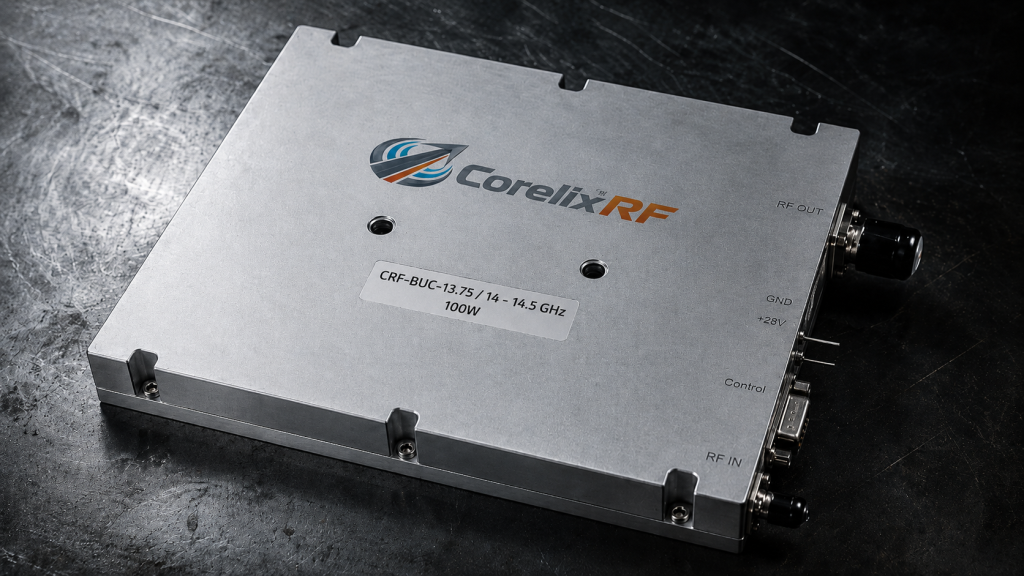
Monitoring telemetry ports represent massive vulnerabilities within high-power electronic shelter systems. The CRF-BUC-13.75-14.5GHz-100W features complete optocoupler isolation across its RJ45 ethernet communication interface. Optocouplers translate electrical signals into light, crossing physical gaps without sharing conductive grounds. This optical barrier stops chassis return currents dead, protecting sensitive monitoring networks permanently. Field operators never experience phantom VSWR alarms resulting from corrupted telemetry data again. Here is the deal, optical isolation costs more but saves millions during deployments. We refuse building cheap interfaces knowing they fail during critical tactical operations.
● Evaluating 36-72V DC input tolerance under heavy load
Military supply voltages fluctuate wildly during intense generator loading sequences. Our module accepts wide-ranging 48V nominal inputs, specifically surviving 36-72V DC swings effortlessly. Internal switching regulators maintain stable core voltages regardless of external power delivery chaos. This massive input tolerance prevents sudden amplifier resets when massive radar arrays activate nearby. We include robust alarm protection functions monitoring temperature and current dynamically. You might be wondering, how does this eliminate ground loops exactly? By accepting massive voltage drops across supply lines, our regulators ignore resistive ground faults.
CRF-BUC-13.75-14.5GHz-100W Core Parameters
| Specification | Value | Engineering Benefit |
| Frequency Range | 13.75 / 14 – 14.5 GHz | Covers standard Ku-band operations |
| Rated Output | 50 dBm / 100 W | Delivers massive jamming power |
| Supply Voltage | 48 V (36 – 72 V) | Survives severe voltage drops |
7. What Are the Mechanical and Environmental Defenses of This CorelixRF Module?
● Rigid 225 × 151 × 141 mm milled chassis for optimal RF grounding
Microwave engineering demands absolute mechanical rigidity preventing phase noise degradation under vibration. We mill our 225 × 151 × 141 mm chassis from solid aluminum blocks directly. This monolithic structure eliminates internal resistive joints, providing perfect electrical ground planes continuously. Weighing 5.5 kg, this heavy metal casing absorbs both thermal loads and physical shocks. Consider this fact, lightweight folded sheet metal chassis cannot support 100W Ku-band transmitters. Our rigid housing guarantees consistent electrical performance across decades of harsh deployments.
● Three-pin aviation connector mating for robust power delivery
Standard commercial power connectors melt under 450W continuous power consumption loads routinely. We equip the CRF-BUC-13.75-14.5GHz-100W utilizing heavy-duty three-pin aviation connectors exclusively. These military-grade interfaces lock securely, defying extreme vibration profiles without losing contact pressure. Thick gold-plated pins handle massive current surges seamlessly while minimizing contact resistance permanently. Pay close attention now, your power connector determines your overall system reliability fundamentally. Sourcing premium aviation connectors eliminates mysterious voltage drops crippling lesser amplifier designs.
● Sustaining stable phase noise amidst extreme shock profiles
Electronic warfare depends heavily upon maintaining ultra-clean phase noise characteristics constantly. Our rigid mounting architecture secures delicate oscillator circuits against microphonic vibration effects perfectly. The module delivers exceptional phase noise performance: ≤-65 dBc/Hz @ 100Hz routinely. Even under heavy chassis vibration, internal grounding remains solid, preventing noise floor elevation. What is the real story? Poor mechanical design ruins premium RF components immediately. We merge heavy-duty mechanics alongside delicate microwave electronics harmoniously.
8. How Do We Validate System Stability After Component Integration?
● Running 100W rated power continuous wave tests
Validating true amplifier performance requires brutal continuous wave burn-in testing protocols. We push every module producing 50 dBm continuously across extended thermal cycles. These stress tests force hidden grounding flaws exposing themselves before shipping occurs. Technicians monitor heat dissipation profiles using advanced thermal imaging cameras precisely. This is where it gets interesting, many competitors only specify pulsed power capabilities. We guarantee our 100W rating survives relentless continuous duty operational demands natively.
● Monitoring IM3 across the 13.75-14.5 GHz band
Intermodulation distortion destroys signal clarity during complex multi-carrier jamming operations severely. We measure IM3 meticulously, guaranteeing ≤-25 dBc at 3 dB rated power back-off. Maintaining this linearity requires perfectly clean power rails totally free from ground loops. Any stray return currents injecting noise into bias circuits ruins IM3 metrics instantly. Ready for the good part? Our isolated architecture keeps bias voltages absolutely pristine always. Integrators rely upon our factory test data confidently during system design phases.
● Long-term Ethernet telemetry recording for zero false alarms
Proving our optical isolation effectiveness demands rigorous long-term telemetry data logging. We connect modules toward simulated shelter networks, generating massive RF interference nearby continuously. Our servers monitor RJ45 communication streams, demanding absolutely zero false VSWR alarm triggers. Over hundreds of hours, our optocoupler barriers reject every single induced voltage spike perfectly. Look at it this way, validated telemetry builds operator trust during critical missions. We supply customized test pattern files aiding integrators during their own validation procedures.
System Validation Test Plan
| Test Phase | Methodology | Success Criteria |
| CW Burn-in | 24-hour continuous 50dBm output | Zero thermal throttling events |
| Linearity Check | Two-tone injection at back-off | IM3 ≤-25 dBc |
| Telemetry Stress | Heavy RF induction near RJ45 | Zero packet loss or false alarms |
9. What Maintenance Protocols Prevent Future Grounding Deterioration?
● Periodic torque verification on M5 mounting threads
Maintaining optimal electrical bonding requires disciplined mechanical maintenance schedules consistently. Field crews must verify torque specifications across all M5 chassis mounting threads periodically. Vibration loosens fasteners predictably, necessitating strict tightening regimes utilizing calibrated torque wrenches specifically. The truth of the matter, lazy maintenance destroys perfect engineering designs over time. Establishing mandatory torque checks prevents mysterious ground loops reemerging months after deployment.
● Anti-oxidation treatments for chassis bonding surfaces
Bare aluminum oxidizes rapidly when exposed toward humid salt-fog environments naturally. This microscopic oxide layer acts as an incredibly effective electrical insulator unfortunately. Technicians must apply specialized conductive anti-oxidation pastes between mating chassis surfaces during installation. This compound seals microscopic gaps, preventing oxygen from degrading critical electrical ground paths. Here is the deal, chemical prevention stops electrical failures before they physically manifest.
● Baseline establishment for quiescent current draw
Detecting amplifier degradation early requires establishing solid operational baseline metrics immediately. Engineers record exact quiescent current draws across 48V supply lines during initial commissioning. Any gradual increase signals failing internal components or degrading ground connections developing slowly. Monitoring these baselines enables predictive maintenance scheduling prior toward catastrophic hardware failures. Let me explain why, tracking minor current variations saves entire electronic warfare missions.
10. How Can Integrators Partner with CorelixRF for System Success?
● Reviewing supplied test data and customized pattern files
CorelixRF provides comprehensive factory test data accompanying every single amplifier module dispatched. We supply exact S-parameter files alongside detailed harmonic performance charts for project review. Integrators feed this accurate data directly into their system-level simulation software confidently. What is the real story? Guessing microwave performance leads toward massive architectural failures inevitably. Our transparent engineering truth philosophy eliminates integration guesswork completely.
● Custom RF/IF frequency mapping for specific threat profiles
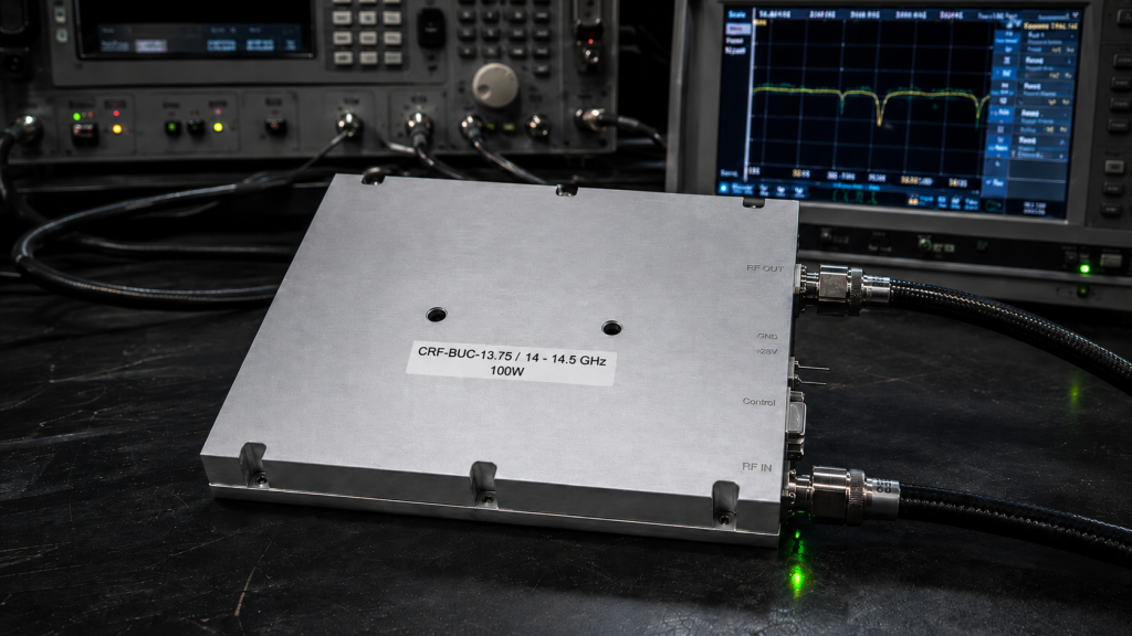
Electronic warfare requires bespoke hardware addressing rapidly evolving global threat landscapes specifically. We customize IF frequency ranges natively, supporting 950-1450 MHz or higher bands seamlessly. Adjusting local oscillator frequencies matches unique customer requirements without sacrificing delivery timelines heavily. You might be wondering, how do we maintain quality during rapid customization cycles? Our modular 225 × 151 × 141 mm architecture supports internal tuning modifications efficiently.
● Leveraging factory-direct engineering support
Solving complex ground loop phenomena requires direct access toward original hardware designers continuously. CorelixRF bypasses standard distribution channels, connecting B2B clients directly alongside our engineering veterans. We review your specific shelter layouts, suggesting optimal grounding architectures before manufacturing begins. Consider this fact, direct factory communication accelerates deployment schedules significantly. Partnering with a 30-year RF factory guarantees accessing unparalleled microwave troubleshooting expertise directly.
Integration Support Matrix
| Support Tier | Deliverable | Client Benefit |
| Data Package | S-parameters, IM3 charts | Accurate system simulation |
| Customization | bespoke IF/RF frequency | Targeted threat engagement |
| Direct Engineering | Architecture review | Eliminating ground loops early |
Final Thoughts
Mastering electronic warfare hardware requires confronting harsh physical realities governing microwave energy and high-current paths. Relying strictly upon software diagnostics masks dangerous analog grounding faults, risking entire mission deployments unnecessarily. Integrating optical isolation alongside massive milled chassis structures eliminates phantom alarms permanently. Connect with CorelixRF directly, securing your next system integration utilizing proven engineering truth.
FAQ
Q1: What triggers false VSWR alarms in large electronic warfare shelters?
Heavy jamming causes high current returns traversing chassis grounds, shifting reference voltages. These shifts corrupt weak telemetry pins, creating phantom alarms without actual hardware damage.
Q2: How do poor system grounding and high current returns interact?
Massive 48V return currents seek low-impedance paths through loose, vibrating metal chassis joints. This creates voltage drops across interfaces, disrupting sensitive communication electronics nearby entirely.
Q3: Why are weak-signal pins highly vulnerable in high-power systems?
RJ45 ethernet lines sit close toward massive RF decks, absorbing stray electromagnetic radiation. Induced spikes exceed standard logic gate thresholds, commanding instant, false protective shutdowns automatically.
Q4: How can we isolate and measure ground loops in the field?
Engineers utilize high-speed oscilloscopes paired with isolated differential probes across suspected resistive joints. Clamp meters also verify whether direct-current flows properly along designated ground straps.
Q5: What role does thermal dissipation play in exacerbating grounding issues?
The 450W power consumption causes significant aluminum chassis expansion, warping mating surfaces microscopically. This thermal cycling introduces fluctuating resistance, destroying previously solid electrical ground bonds eventually.