
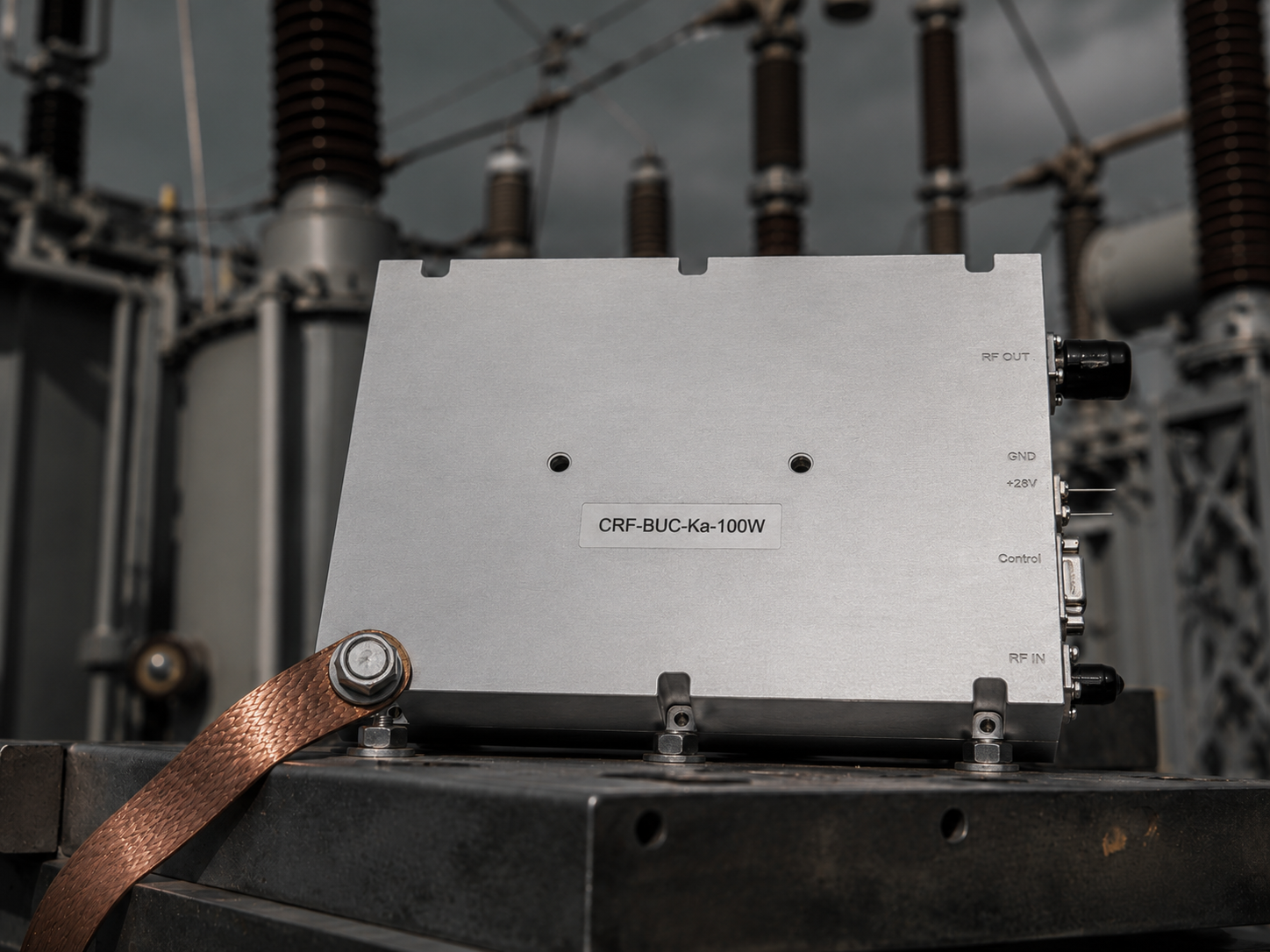
Engineers face brutal realities inside high-voltage substations daily. Your monitoring displays flash erratic warnings constantly. Vehicle-mounted countermeasure systems exhibit screen-flickering VSWR alarms reducing transmit power unexpectedly. Here is the deal. Thirty seconds of unexpected downtime wreaks havoc upon grid dispatch operations. Massive fault currents exploit weak grounding paths maliciously. Rogue transient voltages infiltrate sensitive telemetry lines. We developed rigorous field methods solving these exact hardware failures.
Severe Electromagnetic Realities Inside Substation Environments You might be wondering Why do standard commercial amplifiers fail spectacularly near switchyards? Massive transformers generate immense magnetic flux fields continually. Breaker actuations discharge terrifying amounts of localized energy. Substation earth grids experience radical voltage shifts during phase faults. Your VSAT terminal sits directly amid this violent electrical chaos. Ground resistance degrades naturally over years due to severe salt fog corrosion. Contact points oxidize silently beneath thick industrial grime layers. We measure ground bonds drifting from milliohms toward tens of ohms. High resistance forces rogue electrons down unexpected metallic pathways. Fault currents seek any low-impedance route back toward source transformers. Coaxial cable shields offer highly attractive return routes. What is the real story? Poorly bonded chassis components become deadly current conduits. Standard RF hardware lacks sufficient isolation against such brute-force electrical assaults. Physical isolation barriers remain absolutely necessary. Frontline technicians waste countless hours rebooting seemingly frozen microcontrollers. We analyze actual physical layer breakdowns instead. RF engineers must understand applied electromagnetics thoroughly.
Substation Environmental Stress Factors
| Stress Factor | Physical Mechanism | Hardware Impact |
| Ground Potential Rise | Massive fault current injection | Chassis voltage elevation |
| Switching Transients | Breaker arc discharge | High-frequency noise coupling |
| Salt Fog Corrosion | Chemical metal degradation | Ground resistance increase |
| Magnetic Induction | 50Hz transformer flux | Low-frequency shield currents |
Decoding False Triggers Upon Weak Logic Interfaces
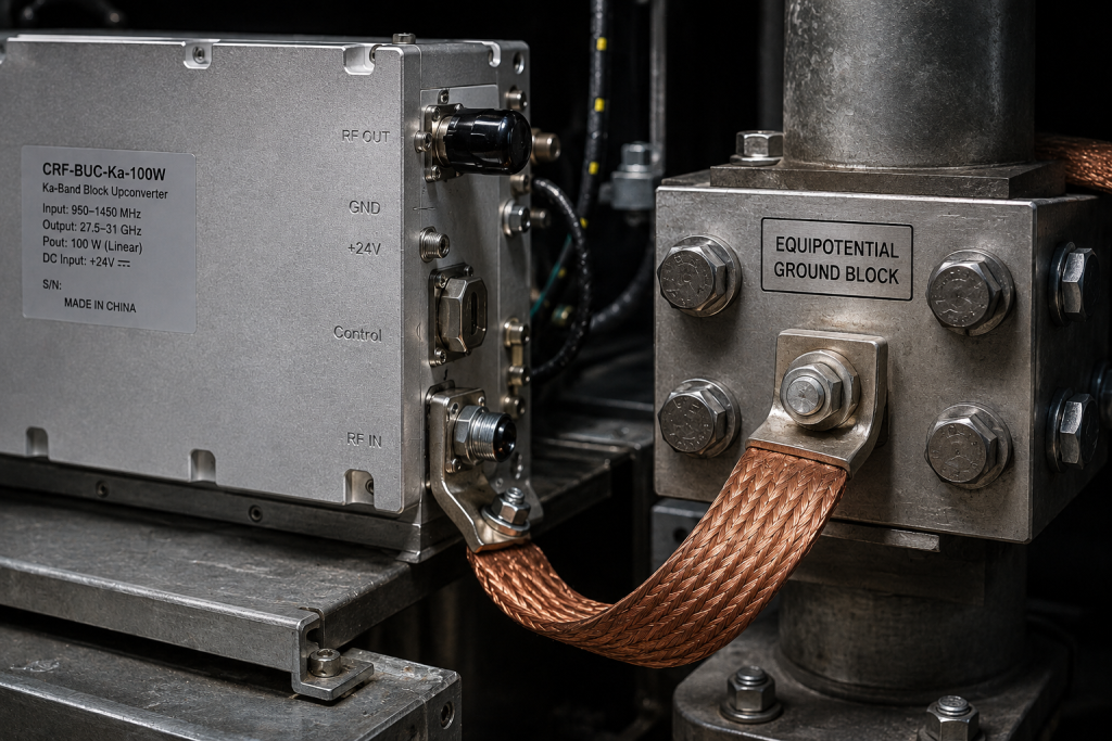
But here’s the kicker Microprocessors operate utilizing extremely tight voltage tolerances. Modern Ethernet interfaces utilize differential signaling meant for pristine data centers. RJ45 connectors feature tiny metallic pins spaced millimeters apart. When massive return currents surge across communication shields, disaster strikes immediately. Inductive coupling forces severe transient spikes onto RX and TX data lines. This is where it gets interesting A sudden 15V spike overpowers internal 3.3V logic gates effortlessly. Substation BUCs interpret these rogue spikes as legitimate mute commands. Often, false temperature limit warnings trigger system-wide shutdowns unnecessarily. We see VNA curves collapsing completely at high-frequency bands. BUC performance degrades while technicians stare confusedly at perfect weather outside. Unbalanced parasitic capacitance converts common-mode noise into differential-mode errors. Current flowing across high-resistance ground straps ruins signal integrity permanently. You must block these pathways physically using galvanic isolation. CorelixRF engineers spent decades analyzing these specific failure modes. We mandate hardcore hardware decoupling for every remote terminal application. Reliance upon cheap unshielded plastic connectors guarantees field failures.
Logic Pin Vulnerability Metrics
| Interface Type | Standard Threshold | Failure Threshold | Field Observation |
| RJ45 Ethernet | 2.5V Differential | 5V Peak Transient | Link drops suddenly |
| RS-485 Control | 5V Common Mode | 12V Inductive Spike | Corrupted command parsing |
| Alarm Pins | 3.3V TTL | 8V Surge | False thermal shutdown |
| Power Supply | 48V DC Nominal | 72V Overvoltage | Internal fuse rupture |
Hardcore Field Isolation and Measurement Tactics
Ready for the good part? Proper field diagnosis requires serious instrumentation. Leave your cheap digital multimeters inside your truck. Grab a high-bandwidth oscilloscope equipped with dedicated differential isolated probes. Never clamp standard grounded probes onto active substation electronics. Listen closely. You risk destroying expensive test equipment instantly. Disconnect that main RJ45 cable from your amplifier chassis. Place differential probes across those exposed logic pins carefully. Trigger a local switchgear operation manually if safety protocols allow. Watch your screen capture massive common-mode voltage spikes clearly. Next, deploy a professional earth resistance clamp meter. Clamp directly around specific copper bonding wires connecting chassis grounds. We frequently measure 15 ohms where 0.1 ohms must exist. High impedance forces return currents straight through your Ethernet shielding. Reconnect all communication lines temporarily. Measure current flowing across those thin outer RJ45 metal shells. Detecting significant amperage proves your logic ground remains improperly floating. Professional troubleshooting relies upon empirical measurement rather than blind guessing.
Field Troubleshooting Instrumentation
| Instrument Required | Specific Measurement Target | Expected Healthy Value |
| Differential Oscilloscope | Transient voltage spikes | Under 100mV peak |
| Earth Clamp Meter | Chassis bonding impedance | Under 0.5 ohms |
| Spectrum Analyzer | In-band spurious emissions | Below -55 dBc |
| Current Probe | Ethernet shield current | Zero milliamperes |
The CorelixRF Hardware Solution Architecture
Let’s dig deeper. We engineered the CRF-BUC-Ku-100W specifically for these hostile domains. Our design team abandoned standard commercial telecom connectors entirely. We utilize heavy-duty three-pin aviation connectors handling 48V DC power. Communication flows securely through dedicated ruggedized RJ45 aviation housings. These thick metal housings bond directly into solid aluminum chassis blocks. Here is the truth. We dynamically isolate internal logic grounds from main exterior chassis grounds. Internal high-speed optocouplers block stray substation voltages effectively. Review our stringent RF performance data objectively. Our BUC covers 13.75 through 14.5 GHz seamlessly. We output 50 dBm rated power continuously. Small signal gain exceeds 68 dB with incredible flatness. Gain stability remains within ±2 dB across -40 to 60 °C. Phase noise measures ≤-65 dBc/Hz at 100Hz offsets. We integrated receive rejection filtering alongside built-in high-power isolators. This 5.5 kg unit carries an IP65 environmental protection rating. We fully comply with stringent GJB 9001C military quality standards.
CRF-BUC-Ku-100W Key Specifications
| Parameter Name | Specification Value | Engineering Benefit |
| RF Frequency Range | 13.75 – 14.5 GHz | Broad Ku-band coverage |
| Rated Output Power | 50 dBm / 100 W | High-penetration uplink |
| Small Signal Gain | ≥68 dB | Robust signal amplification |
| Phase Noise | ≤-65 dBc/Hz @ 100Hz | Clean digital modulation |
| Operating Temp | -40 to 60 °C | Extreme weather resilience |
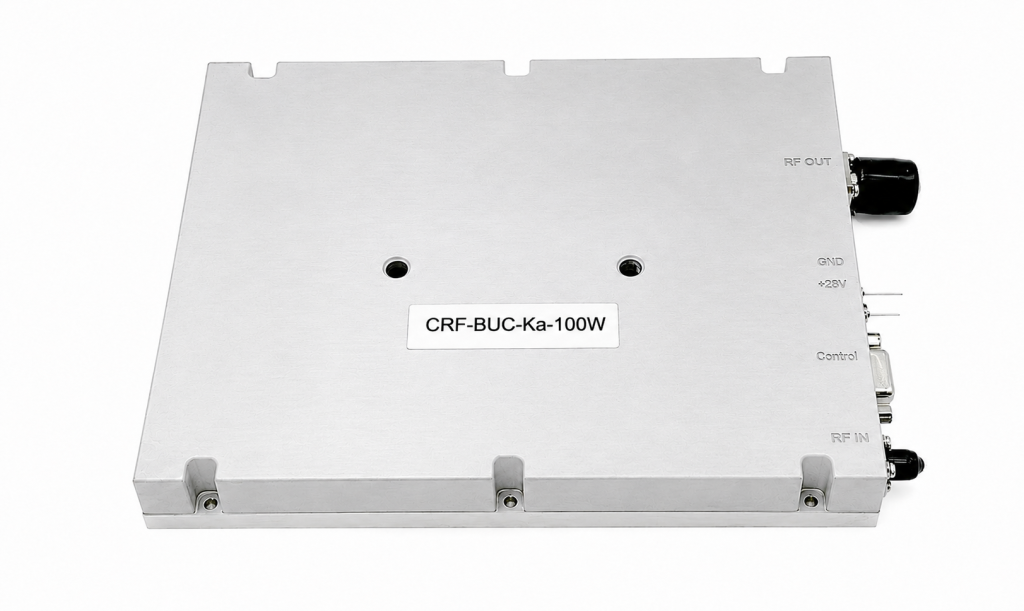
Designing Indestructible VSAT Ground Topologies Now consider this. Deploying superior RF hardware solves merely half your engineering battle. System integrators must execute uncompromising grounding protocols locally. We demand strict single-point earthing topologies for every site. Your antenna pedestal, equipment rack, and amplifier must share one massive equipotential block. Tie this central block into primary substation grids using heavy copper. What does this mean? You eliminate dangerous potential differences between separate interconnected components. Never daisy-chain ground wires across multiple electronic devices randomly. Run individual thick bonds from every chassis directly toward that central node. Shielded twisted pair data cables cause havoc if grounded bilaterally. Ground communication shields strictly at your indoor baseband rack side. Leave outdoor BUC shield connections floating capacitively. This technique breaks low-frequency ground loops instantly while maintaining high-frequency shielding. Poor grounding modulates 50Hz AC hum directly onto microwave transmission carriers. Our hardware guarantees maximum spurious signal rejection hitting ≤-55 dBc. Hardcore engineering demands relentless perfection regarding physical layer installation.
Recommended Grounding Topology Rules
| Component | Grounding Method | Forbidden Practice |
| CRF-BUC Chassis | Direct thick copper bonding | Daisy-chaining to LNB |
| Ethernet Shield | Ground at indoor modem only | Grounding at both ends |
| Antenna Pedestal | Welded strap to main grid | Relying on concrete rebar |
| IF Coaxial Cable | Surge arrestor at building entry | Bypassing lightning arrestors |
Final Engineering Verdict
Engineers must respect brutal physics inside high-voltage utility environments. Massive ground return currents destroy weak communication logic paths mercilessly. Proper physical isolation techniques save critical satellite telemetry networks. CorelixRF builds ruggedized Ku-band hardware solving these specific electromagnetic anomalies permanently. Contact our engineering team today regarding detailed CRF-BUC-Ku-100W datasheets and integration support.
FAQ
Q1: What causes false triggers on weak current monitoring pins?
Massive ground potential rises force transient return currents across communication cable shields. These currents induce high voltage spikes onto sensitive RX and TX lines. Microcontrollers misinterpret these rogue spikes as valid mute or shutdown commands.
Q2: How does the CRF-BUC-Ku-100W handle severe electromagnetic interference? We utilize rugged aviation connectors bonding directly against solid aluminum chassis blocks. Internal optocouplers physically isolate logic grounds from exterior high-voltage transients. Built-in receive rejection filtering eliminates spurious out-of-band signals completely.
Q3: Why do VNA curves collapse at high frequency bands during testing?
Poor grounding allows wideband switching noise injection directly into measurement equipment ports. Unbalanced parasitic capacitance converts common-mode substation noise into differential-mode errors. This elevated noise floor destroys high-frequency vector network analyzer dynamic range.
Q4: What are the strict grounding rules for substation VSAT terminals?
Implement absolute single-point earthing topologies utilizing a central equipotential block. Connect this block directly into main substation earth grids using heavy copper. Never ground Ethernet communication shields simultaneously at both equipment ends.
Q5: What specific RF parameters define the CorelixRF 100W Ku-band amplifier? Our unit delivers 50 dBm rated output power across 13.75 to 14.5 GHz. Small signal gain exceeds 68 dB alongside a 20 dB adjustment range. Phase noise remains strictly below -65 dBc/Hz at 100Hz offsets.
Move from troubleshooting to an RF front-end review
For substation or rugged VSAT links, ask the factory to review grounding, shielding, BUC/LNB path, amplifier power margin, signal source stability, cable loss and environmental limits as one RF chain instead of isolated symptoms.
Recommended next step: send the operating band, required output power, duty cycle, load condition, control interface, cooling limit, protection behavior and required FAT documents. CorelixRF can map this substation VSAT signal interference requirement to a standard platform, a controlled modification or a custom RF build.